Page is loading ...

MG-1006
ECN 5355-MA 140303
CONDENSING GAS FURNACE
INSTALLATION AND OPERATION MANUAL
MODELS:
CHB1-50N CDB1-50N
CHB1-75N CDB1-75N
CHB1-100N CDB1-100N
CHB1-125N CDB1-125N
: IF YOU DO NOT FOLLOW THE SAFETY PRECAUTIONS BELOW AND IN THIS MANUAL, A
FIRE OR EXPLOSION MAY RESULT CAUSING PROPERTY DAMAGE, PERSONAL INJURY, OR LOSS OF
LIFE.
DO NOT STORE OR USE GASOLINE OR OTHER FLAMMABLE VAPORS AND LIQUIDS IN THE VICINITY OF
THIS OR ANY OTHER APPLIANCE.
WHAT TO DO IF YOU SMELL GAS:
• DO NOT TRY TO LIGHT ANY APPLIANCE.
• DO NOT TOUCH ANY ELECTRICAL SWITCH; DO NOT USE ANY PHONE IN YOUR BUILDING.
• LEAVE THE BUILDING IMMEDIATELY.
• IMMEDIATELY CALL YOUR GAS SUPPLIER FROM A NEIGHBOR’S PHONE. FOLLOW THE GAS
SUPPLIER’S INSTRUCTIONS.
• IF YOU CANNOT REACH YOUR GAS SUPPLIER; CALL THE FIRE DEPARTMENT.
INSTALLATION AND SERVICE MUST BE PERFORMED BY A QUALIFIED INSTALLER, SERVICE AGENCY OR
THE GAS SUPPLIER. (REFERRED TO IN THESE INSTRUCTIONS AS A QUALIFIED HEATING
CONTRACTOR).
PLEASE READ THESE INSTRUCTIONS PRIOR TO INSTALLATION, INITIAL FIRING, AND BEFORE
PERFORMING ANY SERVICE OR MAINTENANCE. THESE INSTRUCTIONS MUST BE LEFT WITH THE
HOMEOWNER AND SHOULD BE RETAINED FOR FUTURE REFERENCE BY QUALIFIED SERVICE
PERSONNEL.
THERMO PRODUCTS, LLC.
BOX 217
NORTH JUDSON, IN 46366
PHONE: (574) 896-2133
MADE IN USA

i
I. SAFETY INFORMATION
This and the following page contain reproductions of the various warning and instruction labels
placed on the Thermo Pride Condensing Gas Furnaces. Please read and comply with the contents
of these labels.

All installations and services must be performed by qualified service personnel.
ii
This and the previous page contain reproductions of the various warning and instruction labels
placed on the Thermo Pride Condensing Gas Furnaces. Please read and comply with the contents
of these labels.
WARNING:
If you do not follow these instructions exactly, a
fire or explosion may result causing property damage,
personal injury or loss of life.
390540
1. Set thermostat to lowest setting, and, if equipped, set the operating
mode to "COOL" or "OFF".
2. If service is to be performed, turn off all electric power to the
appliance.
3. To turn off gas control valve, remove the burner compartment cover.
4. Move the gas control switch to the "OFF" position.
5. Replace the burner compartment cover.
1. STOP! Read the safety information above on this label.
2. Set the thermostat to the lowest setting.
3. Turn off all electric power to the appliance.
4. This appliance is equipped with a hot surface igniter that
automatically lights the burner. Do not try to light the burner by
hand.
5. Move the gas control switch to the "OFF" position.
6. Wait five (5) minutes to clear out any gas. Then smell for gas,
including near the floor or ground. If you smell gas, STOP! Follow
"B" in the safety information above on this label. If you don't smell
gas, go to the next step.
7. Move the gas control switch to the "ON" position.
8. Turn on all electric power to the appliance.
9. Set thermostat to desired setting, and, if equipped, set the operating
mode to "HEAT".
10.If appliance will not operate, follow the instructions "To Turn Off
Gas To Appliance" and call your service technician or gas supplier.
A. This appliance does not have a pilot. It is equipped with a hot
surface igniter that automatically lights the burner. Do not try to
light the burner by hand.
B. BEFORE OPERATING smell all around the appliance area for gas.
Be sure to smell next to the base of unit because some gas is
heavier than air and will settle on the floor or ground.
WHAT TO DO IF YOU SMELL GAS
? Do not try to light any appliance.
? Do not touch any electric switch; do not use any phone in your
building.
? Immediately call your gas supplier from a neighbor's phone.
Follow the gas supplier's instructions.
? If you cannot reach your gas supplier, call the fire department.
C. Use only your hand to move the gas control switch. Never use tools.
If the switch will not move by hand, don't try to repair it, call a
qualified service technician. Force or attempted repair may result in
a fire or explosion.
D. Do not use this appliance if any part has been underwater.
Immediately call a qualified service technician to inspect the
appliance and to replace any part of the control system and any gas
control which has been underwater.

All installations and services must be performed by qualified service personnel.
iii
The following safety information should be read, understood, and followed by the installer.
1. Use only with type of gas approved for this furnace. Refer to furnace rating plate.
2. Connect this furnace to an approved vent system only. Combustion products must be carried outdoors. Refer to
Section III, D thru H, of this manual.
The following pages contain various warnings and cautions found throughout the Thermo Pride Highboy and
Dual Poise Condensing Gas Furnace Manual. Please read and comply with the statements below.
: This furnace is not to be used for temporary heating of buildings or structures under construction.
: These high efficiency condensing furnaces are not certified for and shall not be vented into a
standard or any type of chimney.
: These furnaces may not be common vented with any other appliance.
: The vent and air intake elbows must be kept away from bushes, shrubs or any vegetation that may
restrict the flow of flue products. It must also be kept clear of any leaves, weeds or other combustible materials.
Keep the vent hood clear of snow. Avoid locating the terminals in areas where standing water or condensate
drippage may be a problem.
: This CHB1/CDB1 furnace has been designed to be installed as a direct vent system. The failure to
install the vent/air intake system as specified in these instructions will void the heat exchanger warranty and may
result in property damage, personal injury or loss of life.
: Outside combustion air must not come from an area that is directly adjacent to a pool, hot tub or
spa. Measures should be taken to prevent the entry of corrosive chemicals or vapors to the combustion and
ventilation air supply. Such chemicals include but are not limited to chlorinated and/or fluorinated hydrocarbons
such as found in refrigerants, aerosol propellants, dry cleaning fluids, degreasers and removers. Other harmful
compounds may come from bleaches, air fresheners or mastics. Vapors from such products can form acid
compounds when burned in a gas flame. Should acid compounds form in your furnace; it may reduce the life of
the furnace.
: Because of the potential of odorant fade, a gas leak may not be detected by smell. If this furnace
is installed below grade, contact your gas supplier for a gas detector.
: Turn off power to furnace before it is placed into service. The gas piping system must have been
leak tested by a qualified heating contractor.
: It may be necessary to purge the air out of the gas line for initial start-up of the furnace after
installation. This should be done by a qualified heating contractor. If excessive gas escapes when purging the
gas supply at the union, allow the area to ventilate for at least 15 minutes before attempting to start the furnace.
LP gas is especially dangerous because the specific gravity of LP gas allows it to accumulate at floor level at a
dangerous concentration. For remainder of operating instructions, reference Users Information Manual.
: Heat exchanger oil will burn off on initial firing creating an unpleasant odor. To prevent this
odor from occurring more than once, it is suggested that:
1. A window(s) be opened.
2. The thermostat set at highest setting.
3. The furnace remain running at conditions 1&2 for 30 minutes or until odor has dissipated.

All installations and services must be performed by qualified service personnel.
iv
: The CHB1/CDB1 furnace models are sealed combustion design, which does not require an air
shutter adjustment (air shutters are not used) for proper flame characteristics. Burner box access cover must
always be secured with all screws in place and tightened before operating furnace.
: Personal injury or property damage could result from repair or service of this furnace by anyone
other than a qualified heating contractor. Only the homeowner/user routine maintenance described in the Users
Information Manual may be performed by the user.

All installations and services must be performed by qualified service personnel.
v
INDEX
SECTION BEGINNING PAGE
I. SAFETY INFORMATION i
II. FURNACE SPECIFICATIONS 1
III. GENERAL INSTALLATION 5
A. CODES AND CLEARANCES 5
B. FURNACE LOCATION 6
B1.CDB1 HORIZONTAL APPLICATION 7
C. REPLACING EXISTING FURNACE FROM A COMMON VENT 8
D. GENERAL REQUIREMENTS FOR VENTING CHB1/CDB1 9
E. SIDEWALL VENTING
11
E1. SINGLE PIPE (SIDEWALL) VENTING OPTION 14
F. INSTALLATION OF OUTSIDE VENT/AIR INTAKE TERMS. 14
G. CONNECTING FURNACE TO ROOF VENT/AIR TERMS. 16
H. CONNECTING FURNACE TO VENT/AIR INTAKE TERMS. 17
I. CONDENSATE DRAIN LINE & TRAP ASSY. 22
J. GENERAL GAS PIPING 25
J1. REQUIREMENTS & SIZING OF DUCTWORK 26
K. FILTERS 29
L. WIRING 31
IV. STARTING THE UNIT 34
A. SEQUENCE OF OPERATIONS 34
B. INITIAL START-UP 36
C. ADJUSTMENT OF BTU INPUT RATE 36
D. BURNER ADJUSTMENT 37
E. FURNACE CHECKOUT PROCEDURE 38
VI. INSTALLER’S INSTRUCTIONS TO USER 39
VII. TROUBLESHOOTING 40
APPENDIX – A REPLACEMENT PARTS LIST 46
APPENDIX – B WIRING DIAGRAMS 50

All installations and services must be performed by qualified service personnel.
1
II. FURNACE SPECIFICATIONS
CHB1 SERIES
MODEL NO.
CHB1-50
CHB1-75
CHB1-100
CHB1-125
BTU/HR INPUT
50,000
75,000
100,000
125,000
BTU/HR OUTPUT
47,000
72,000
94,000
116,000
HT. OF CASING
44-1/4”
44-1/4”
44-1/4”
44-1/4”
WIDTH OF CASING
17”
17”
21”
24”
DEPTH OF CASING
27-1/2”
27-1/2”
27-1/2”
27-1/2”
WARM AIR OUTLET
15 x 18
15 x 18
19 x 18
22 x 18
RETURN AIR INLET
25 x 16
25 x 16
25 x 16
25 x 16
DIA. OF FLUE
2”
2”
3”
3”
DIA. OF COMBUSTION
AIR INTAKE
2” 2” 3” 3”
CFM @ .2” & .5” w.c.
EXTERNAL STATIC PRESSURE
.2” .5” .2” .5” .2” .5” .2” .5”
@HI SPEED
1100 860
1600 1380
1940 1700
2770 2060
@MH SPEED
1000 720
1250 1150
1720 1540
1800 1700
@ML SPEED
-- --
1030 930
1530 1380
1730 1600
@LO SPEED
610 420
820 700
1340 1220
1670 1550
TEMPERATURE RISE
70
70
70
70
BLOWER MOTOR HP
.20
.41
.50
.75
NO. OF SPEEDS
3
4
4
4
RUN CAPACITOR
10 mfd
10 mfd
10 mfd
10 mfd
LARGEST RECOMMEDED
AIR CONDITIONER
2 Ton 3.5 Ton 4 Ton 5 Ton
SIZE OF FILTERS
24-3/4” x 15-3/4”
24-3/4” x 15-3/4”
24-3/4” x 15-3/4”
24-3/4” x 19-3/4”
NOTES:
1. BTU output based on annual fuel utilization efficiency rated by manufacturer.
2. On all outlet and inlet dimensions, the first dimension is width.
3. To permit largest recommended air conditioning (at .5 static pressure), selection of the highest motor speed is
required.

All installations and services must be performed by qualified service personnel.
2
CDB1 SERIES
MODEL NO.
CDB1-50
CDB1-75
CDB1-100
CDB1-125
BTU/HR INPUT
50,000
75,000
100,000
125,000
BTU/HR OUTPUT
47,000
70,000
94,000
116,000
HT. OF CASING
46-1/4”
46-1/4”
46-1/4”
46-1/4”
WIDTH OF CASING
17”
17”
21”
24”
DEPTH OF CASING
27-1/2”
27-1/2”
27-1/2”
27-1/2”
WARM AIR OUTLET
15 x 18
15 x 18
19 x 18
22 x 18
RETURN AIR INLET
15 x 22
15 x 22
19 x 22
22 x 22
DIA. OF FLUE
2”
2”
3”
3”
DIA. OF COMBUSTION
AIR INTAKE
2” 2” 3” 3”
CFM @ .2” & .5” w.c.
EXTERNAL STATIC PRESSURE
.2” .5” .2” .5” .2” .5” .2” .5”
@HI SPEED
1120 930
1530 1340
1830 1590
2280 2010
@MH SPEED
1000 750
1270 1110
1660 1460
1830 1650
@ML SPEED
-- --
1050 930
1520 1340
1750 1570
@LO SPEED
616 420
850 720
1370 1230
1660 1530
TEMPERATURE RISE
70
70
70
70
BLOWER MOTOR HP
.20
.41
.50
.75
NO. OF SPEEDS
3
4
4
4
RUN CAPACITOR
10 mfd
10 mfd
10 mfd
15 mfd
LARGEST RECOMMEDED
AIR CONDITIONER
2 Ton 3.5 Ton 4 Ton 5 Ton
SIZE OF FILTERS
21-3/4” x 14”(2)
21-3/4” x 14”(2)
21-3/4” x 14”(2)
21-3/4” x 14”(2)
NOTES:
1. BTU output based on annual fuel utilization efficiency rated by manufacturer.
2. On all outlet and inlet dimensions, the first dimension is width.
3. To permit largest recommended air conditioning (at .5 static pressure), selection of the highest motor speed is
required.
4. Electrical characteristics at 115 volts, 60 Hz., 1 phase (less than 15 amps. for all models).
5. All specifications are subject to change without notice.

All installations and services must be performed by qualified service personnel.
3
INSTALLATION PARTS PACKAGES - CHB1-50/75
PARTS PACKAGE
#S00S4405/4406
DESCRIPTION PART # QUANTITY
2-3/8” ID radiator hose
410017
1
Thermostat lead bushing
350750
1
PVC trap assembly
320816
1
#8 x ¾ coated TEK screws for
mounting trap & inlet/outlet collars
300283 4
11/16” OD x 1/2” ID vinyl tubing
410060
24”
2 x 4 electrical J-box
350024
1
2 x 4 electrical J-box cover
350020
1
#8 x ½ TEK screws for
mounting 2 x 4 J-box
300208 2
#10-32 x ½ green ground screw
300109
1
#10-32 hex nut
300110
1
3/16” dia. star washer
300270
1
Grounding instructions
MG-966
1
Wire nut
300132
2
3” stainless steel hose clamp
300276
2
J-box wire bushing
350016
1
Drain hose grommet
350446
1
Spring clamp, 11/16”
300299
3
Installation notice
MG-987
1
PVC tee assembly, 2” dia.
320818
1
CPVC XPVC adapter
320833
1
Gas Conversion Kit
AOPS7677/7678
1
INSTALLATION PARTS PACKAGES - CHB1-100/125
PARTS PACKAGE
#S00S4407/4408
DESCRIPTION PART # QUANTITY
2-3/8” ID radiator hose
410017
1
Thermostat lead bushing
350750
1
PVC trap assembly
320816
1
#8 x ¾ coated TEK screws for
mounting trap & inlet/outlet collars
300283 4
11/16” OD x 1/2” ID vinyl tubing
410060
24”
2 x 4 electrical J-box
350024
1
2 x 4 electrical J-box cover
350020
1
#8 x ½ TEK screws for
mounting 2 x 4 J-box
300208 2
#10-32 x ½ green ground screw
300109
1
#10-32 hex nut
300110
1
3/16” dia. star washer
300270
1
Grounding instructions
MG-966
1
Wire nut
300132
2
3” stainless steel hose clamp
300276
2
J-box wire bushing
350016
1

All installations and services must be performed by qualified service personnel.
4
Drain hose grommet
350446
1
Spring clamp, 11/16”
300299
3
Installation notice
MG-987
1
PVC tee assembly, 2 x 3” dia.
320817
1
CPVC XPVC adapter
320833
1
Gas Conversion Kit
AOPS7679/7664
1
INSTALLATION PARTS PACKAGES - CDB1-50/75
PARTS PACKAGE
#S00S4409/4410
DESCRIPTION PART # QUANTITY
2-3/8” ID radiator hose
410017
1
Thermostat lead bushing
350750
1
PVC trap assembly
320816
1
#8 x ¾ coated TEK screws for
mounting trap & inlet/outlet collars
300283 6
11/16” OD x 1/2” ID vinyl tubing
410060
24”
2 x 4 electrical J-box
350024
1
2 x 4 electrical J-box cover
350020
1
#8 x ½ TEK screws for
mounting 2 x 4 J-box
300208 2
#10-32 x ½ green ground screw
300109
1
#10-32 hex nut
300110
1
3/16” dia. star washer
300270
1
Grounding instructions
MG-966
1
Wire nut
300132
2
3” stainless steel hose clamp
300276
2
J-box wire bushing
350016
1
Drain hose grommet
350446
1
Spring clamp, 11/16”
300299
3
Installation notice
MG-987
1
PVC tee assembly, 2” dia.
320819
1
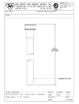
Pipe 2” dia. PVC 15”
14401
1
Bracket
14406
1
CPVC XPVC adapter 320833 1
Gas Conversion Kit AOPS7677/7678 1
INSTALLATION PARTS PACKAGES - CDB1-100/125
PARTS PACKAGE
#S00S4411/4412
DESCRIPTION PART # QUANTITY
2-3/8” ID radiator hose
410017
1
Thermostat lead bushing
350750
1
PVC trap assembly
320816
1
#8 x ¾ coated TEK screws for
mounting trap & inlet/outlet collars
300283 4
11/16” OD x 1/2” ID vinyl tubing
410060
24”
2 x 4 electrical J-box
350024
1
2 x 4 electrical J-box cover
350020
1

All installations and services must be performed by qualified service personnel.
5
#8 x ½ TEK screws for
mounting 2 x 4 J-box
300208 2
#10-32 x ½ green ground screw
300109
1
#10-32 hex nut
300110
1
3/16” dia. star washer
300270
1
Grounding instructions
MG-966
1
Wire nut
300132
2
3” stainless steel hose clamp
300276
2
J-box wire bushing
350016
1
Drain hose grommet
350446
1
Spring clamp, 11/16”
300299
3
Installation notice
MG-987
1
PVC tee assembly, 2 x 3” dia.
320817
1
PVC tee assembly, 2” dia.
320819
1
Pipe 2” dia. PVC 15”
14401
1
Bracket
14406
1
Reducer 2” x 3” PVC
320067
1
CPVC XPVC adapter 320833 1
Gas Conversion Kit
AOPS7679/7664
1
III. GENERAL INSTALLATION
This furnace is equipped with orifices size for operation with natural gas. For conversion to Propane Gas see
instruction in Gas Conversion Section of this manual.
These Category Type IV furnaces are shipped completely assembled and wired (internally). See the Dealer
Receiving and Freight Claim Procedure Section of the price guide for parts shortage or damage. The furnace and
duct system must be adjusted to obtain a temperature rise of 55°F to 85°F (35°F to 65°F CHB1-75) through the
furnace after installation. (See rating label located on side panel inside the furnace vestibule). The installation must
conform with local codes, or in the absence of local codes, with the National Fuel Gas Codes (ANSI Z223.1 or latest
edition) and with these instructions.
: This furnace is not to be used for temporary heating of buildings or structures under construction.
Many of the chemicals used during construction, when burned, form acid bearing condensate that can substantially
reduce the life of the heat exchanger.
It is recommended that a commercially available CO alarm be installed in conjunction with any fossil fuel burning
appliance. The CO alarm shall be installed according to the alarm manufacturer’s installation instructions and be
listed in accordance with the latest edition of the UL Standard for Single and Multiple Station Carbon Monoxide
Alarms, UL 2034, or the CSA International Standard, Residential Carbon Monoxide Alarming Devises, CSA 6.19.
A. CODES AND CLEARANCES
The following items must be considered when choosing the size and location of the furnace.
1. All local codes and/or regulations take precedence over the instructions in this manual and should be followed
accordingly. In the absence of local codes, installation must conform with these instructions, regulations of the
National Fire Protection Association, provisions of National Electrical Code (ANSI/NFPA70 or latest edition),
and the National Fuel Gas Code (ANSI Z223.1 or latest edition).

All installations and services must be performed by qualified service personnel.
6
2. The BTU output capacity of the furnace proposed for installation should be based on a heat loss calculation
made according to the manuals provided by the Air Conditioning Contractors of America (ACCA) or ASHRAE.
3. MINIMUM CLEARANCES TO COMBUSTIBLE MATERIALS
TABLE 1
MODEL NO.
FROM SIDES OF
FURNACE & REAR
FRONT
TOP OF
PLENUM
FROM THE
FLUE OR VENT
SIDE OF
PLENUM
CHB1-50
0 IN.
6 IN.
0 IN.
0 IN.
1 IN.
CHB1-75
0 IN.
6 IN.
0 IN.
0 IN.
1 IN.
CHB1-100
0 IN.
6 IN.
0 IN.
0 IN.
1 IN.
CHB1-125
0 IN.
6 IN.
0 IN.
0 IN.
1 IN.
CDB1-50
0 IN.
6 IN.
0 IN.
0 IN.
1 IN.
CDB1-75
0 IN.
6 IN.
0 IN.
0 IN.
1 IN.
CDB1-100
0 IN.
6 IN.
0 IN.
0 IN.
1 IN.
CDB1-125
0 IN.
6 IN.
0 IN.
0 IN.
1 IN.
The CHB1-50, 75, 100 and 125 furnaces may be installed on combustible flooring. The furnace shall not be installed
directly on carpeting, tile or other combustible material other than wood flooring.
The CDB1-50, 75, 100 and 125 furnaces are to be installed on non-combustible flooring only. The non-combustible
floor bases model no. 50 DA base for CDB1- (50,75) model no. 100 CA base for the model no. CDB1-100 and
model no. 125 CA base for CDB1-125 are available for the counterflow furnaces to allow their installations on
combustible flooring.
These furnaces may be installed in an alcove or in a closet if the minimum clearances to combustible construction
(listed previously) are met. The CDB1 series furnaces may be installed in an attic or crawl space. Refer to section III,
B1 of this installation manual.
The minimum clearances are listed for fire protection. Clearance for servicing the front of the furnaces and to all
points on the furnace requiring access must be 24”*.
*For horizontal furnace installation, refer to section III, B1 of this installation manual.
Equipment must be installed in accordance with regulations of the National Board of Fire Underwriters.
Authorities having jurisdiction should be consulted before installations are made.
B. FURNACE LOCATION
: These high efficiency condensing furnaces are not certified for and shall not be vented into a
standard or any type of chimney.
The following shall be considered for locating the furnace:
1. For best performance locate the furnace so that it is centralized with respect to the duct system and as near as
possible to a floor drain since condensate drainage must be provided.
2. Place the unit so that proper venting can be achieved, with a minimum number of elbows, in accord with the
instructions in this manual.
3. The furnace must be located on a level, dry surface. The furnace must be installed so that the electrical
components are protected from water. If the area becomes wet or damp at times, the
furnace should be raised
above the floor using a concrete base, bricks, patio blocks, etc.
NOTICE: Ensure furnace is level after installation to ensure proper drainage and operation.

All installations and services must be performed by qualified service personnel.
7
4. This furnace must be connected to a drain in accordance with these instructions. If it is not practical to connect
the unit to a drain, a condensate pump must be used and can be ordered as an
accessory, part number 350225. If
an acid neutralizer kit is required by local code or the customer, it is available under part number 320095.
B1. CDB1 HORIZONTAL APPLICATION
The CDB1-50, 75, 100, and 125 furnaces may be installed in a horizontal position by placing the furnace on the left
or right side (as viewed from the front in the upright position).
For left or right horizontal applications of the CDB1 series units, the rollout switch located on the burner box must
be moved to the pre-punched mounting holes on the side of the burner box. Screws are provided in pre-punched
holes at the required limit location. Remove these screws and use them to mount the limit to new location. Utilize
previously removed limit mounting screws to fill voided holes at previous limit location (See Figure 1).
For a right side horizontal application of the CDB1 series units, the hose from the single tap pressure switch (top
switch) is already connected correctly (See Figure 1).
For a left side horizontal application of the CDB1 series units, the hose from the single tap pressure switch (bottom
switch) must be moved to the lower front tap on the face of the collector box. Use the black cap removed from this
tap to plug the original pressure switch tap.
NOTE: The hose, when moved, must be shortened (cut) to ensure that no excess hose exists to cause a sag, loop, or
"water trap".
For a right side horizontal application of the CDB1 series units, the auxiliary limit switch located on the right side of
the house air blower must be moved to the bracket on the opposite (left) side of the blower (See Figure 1).
NOTE: When the CDB1 is installed as horizontal unit, it is imperative that the auxiliary limit switch and bracket be
located on the upper side of the house air blower; the burner rollout switch located on the burner box be relocated to
the side of the burner box; and that the hose from the single tap pressure switch be connected to the lower tap on the
front of the collector box (See Figure 1).

All installations and services must be performed by qualified service personnel.
8
Figure 1
The horizontal furnace installation should be on a service platform large enough to allow for proper clearances on all
sides and service access to the front of the furnace (See Table 1). If the furnace is suspended, it must be supported at
both ends and in the middle with clearance allowed for removal of both access doors. Gas supply line contact is only
permissible between lines
formed by the intersection of the top and two sides of the furnaces casing and the building
joists, studs, or framing (See Figure 1).
Equipment must be installed in accordance with regulations of the National Board of Fire Underwriters and
the National Fuel Gas Code. Authorities having jurisdiction should be consulted before installations are
made.
C. Replacing An Existing Furnace From A Common Vent
: These furnaces may NOT be common vented with any other appliance.

All installations and services must be performed by qualified service personnel.
9
D. General Requirements For Venting Models CHB1 / CDB1
The CHB1 / CDB1 furnace venting system must be installed by a qualified service person in accordance with local
installation codes and these instructions. In the absence of applicable local codes, conform to the National Fuel Gas
Code, NFPA 54 /ANSI Z223.1-2002, or latest edition thereof.
Installation shall, at least, conform to the following requirements.
1. The exhaust vent / combustion air intake terminations specified by Thermo Products, in this manual, shall
be used.
2. All plastic pipe and pipefittings sourced to complete the exhaust vent and air intake systems shall be
constructed of rigid PVC (polyvinyl chloride) thermoplastic. All components shall have a wall
thickness equivalent to Schedule 40 series materials.
In addition, all sourced PVC components shall be listed by a nationally recognized testing agency (e.g.
NSF, UL, etc.) as conforming to one (1) or more of the following design standards.
PVC Pipe Designation Design Standard
Cellular Core ASTM-F891
DWV (Drain-Waste-Vent) ASTM-D2665
Schedule 40 ASTM-D1785
3. The exhaust vent pipe and combustion air pipe shall be at least as large as the exhaust vent / air intake pipe
specified by Thermo Products. Size reduction is never permissible. The required exhaust vent / air intake
pipe sizes are:
• nominal 2-inch diameter IPS, Schedule 40 series, PVC thermoplastic pipe, for models CHB1–50 / –
75 & CDB1–50 / –75, or
• nominal 3-inch diameter IPS, Schedule 40 series, PVC thermoplastic pipe, for models CHB1–100 / –
125 & CDB1–100 / –125.
4. The furnace model series CHB1 / CDB1 shall not be common vented with any other appliance, including
those burning solid fuels.
5. All horizontal runs of exhaust vent pipe shall slope upward at least ¼ inch per foot from the outlet of the
furnace (for the model series CHB1), or the outlet of the drain tee (for the model series CDB1) to the vent
termination, beyond the outside wall. This slope will permit proper drainage of the condensate.
Horizontal runs of air intake pipe shall slope downward at least ¼ inch per foot from the outlet of the last
elbow or last horizontal run, before exiting the wall, to the intake termination beyond the outside wall. This
slope will permit proper drainage of any precipitation that enters the intake pipe.
6. The exhaust vent pipe shall be supported at every joint (no more than 4-feet between supports) to
prevent pipe blockage due to condensate trapped at a local low point, or sag, in the vent system.
7. The maximum permissible length of piping (consisting of a combination of straight pipe and a
corresponding number of elbows) permitted is:
• 75 equivalent feet, for the exhaust vent system, and
• 70 equivalent feet, for the combustion air intake system
8. The maximum quantity of Schedule 40 series, type DWV thermoplastic pipe elbows allowed in each system
is listed in Table 2. When counting pipe elbows, all elbows used in the exhaust vent or combustion air

All installations and services must be performed by qualified service personnel.
10
intake systems must be considered. This includes all elbows, or equivalent pipefittings, used inside the
furnace jacket in addition to those used to construct the termination. Furthermore, a credit of 5-feet of
straight pipe may be taken for each elbow, up to maximum of three (3) elbows, which is dropped from the
maximum permissible number for each system.
Table 2: Maximum Permissible Exhaust Vent and Combustion Air Intake Lengths When Using the Maximum
Quantity of Elbows
Thermoplastic
Pipe Vent Size
(Nominal)
2 in. Diameter IPS
3 in. Diameter IPS
Furnace Model
Exhaust or
Intake
Straight
Pipe
Length (ft.)
Maximum
Qty. of
Exhaust
Elbows
1,2
Maximu
m
Qty. of
Intake
Elbows
2
Exhaust or
Intake
Straight
Pipe
Length (ft.)
Maximum
Qty. of
Exhaust
Elbows
1, 2
Maximu
m
Qty. of
Intake
Elbows
2
CHB1 / CDB1-50
35
8
7
-
-
-
CHB1 / CDB1-75
CHB1 / CDB1-100
Not Permitted
35
8
7
CHB1 / CDB1-125
Superscripts:
1
The drain tee supplied with CHB1 / CDB1 furnace model series is considered equivalent to one (1),
90° elbow.
2
Two (2), 45° elbows can be substituted for one (1), 90° elbow.
Care should be taken to design the shortest possible intake and exhaust systems. Each system should contain
as few elbows as possible to insure the satisfactory operation of the furnace. However, system length
should never be less than 8 ft of pipe with two (2), 90 deg. elbows. For best overall operation of the
combustion system, we recommend the actual equivalent lengths for both the constructed intake and the
exhaust systems have approximately the same value.
9. Use a saw designed to cut thermoplastic pipe. All cuts should be made at right angles to the pipe wall.
Smooth jagged edges and remove all burrs and strings. All pipe joints must utilize standard PVC
Schedule 40 series, DWV type elbows, couplings, and fittings. Clean all pipe surfaces at connections
using a fine abrasive material or approved PVC cleaner (primer). Secure all pipe joints using suitable
permanent PVC pipe solvent cement. Joints are NOT to be made by simply gluing raw edges of butted
together vent pipe.
Piping joints inside the furnace vestibule should be sealed with silicone caulk, rather than pipe cement, to
allow for disassembly and removal of piping, if necessary, during maintenance.
NOTICE: DO NOT use silicone caulk to seal the pipe sleeve or coupling to the metal air intake collar
on the burner box. Securing the sleeve or coupling to the collar using a screw is sufficient.
10. Vent connections shall be checked for leakage with the furnace induced draft blower running and with the
vent termination blocked. Use a mild soap and water solution to check for leaks.
11. Vent pipe passing through an unheated space shall be insulated with 1-inch thick, foil-faced fiberglass
insulation, or equivalent, to prevent freezing of condensate within the pipe.
12. No clearance is required from the outer surface of the thermoplastic piping to combustible materials for fire
hazard prevention.
13. Thermo Products does not require screens be installed in the exhaust vent and air intake piping. However,
optional stainless steel screens are available from Thermo Products, should the homeowner request them.

All installations and services must be performed by qualified service personnel.
11
NOTICE: The furnace model series CHB1 / CDB1 may be vented either through the sidewall or the roof.
For sidewall instructions, continue to the following section. For roof venting, refer to Section III G, of this
manual
E. Direct Venting Through a Sidewall
1. Vent and combustion air pipes may pass through a maximum wall thickness of 18 inches. The minimum
wall thickness is 2 inches. Referring to Figure 2, the maximum distance from the outer wall to the center of
the elbow is 12 inches.
Figure 2: Proper Direct Vent Terminations (RH & LH views) and Vent Termination Only w/o
Outside Combustion Air Intake (RH view)
NOTICE: If exterior sidewall building materials are subject to degradation from contact with flue gases or
moisture, a minimum 24-inch diameter shield shall be fabricated from stainless steel or UV-resistant plastic
sheet. The protective shield shall be installed around the vent pipe on the outside wall.
2. The exhaust vent termination elbow shall be installed in accordance with these instructions and any
applicable local codes. Refer to Figures
2 and 3 for typical examples of proper terminations.
a. The exhaust vent termination must be installed in the same atmospheric pressure zone (i.e. on the same
wall) as the air intake termination.
b. The bottom edge of the vent termination elbow must be installed at least 12-inches above the outlet of
intake termination elbow.
c. The horizontal distance between the inlet and exhaust terminations should be minimized, when
possible, and should never exceed 24-inches.
d. The vent and intake systems should utilize the same numbers of elbows and approximately the same
length of straight pipe to reach the outside termination.

All installations and services must be performed by qualified service personnel.
12
Figure 3: Typical Relative Locations of Direct Vent Terminations When Sidewall Venting
3. Exhaust Vent Terminal Location Clearance Requirements
a. The vent terminal shall be located at least 3-feet above any forced air inlet located within 10-feet. Refer
to Figure 4 for a depiction of the minimum required clearances between vent terminations and building
features according to the National Fuel Gas Code (NFGC).
b. The vent terminal shall be at least 12-inches below, 12-inches horizontally from, or 12-inches above,
any door, window, or gravity air inlet into a building. The bottom of the vent terminal shall be located
at least 12-inches above grade.
c. The vent terminal shall not be located:
• over public walkways or over an area where wetting of surfaces by condensate, or water vapor,
could create a nuisance or hazard,
• near soffit vents, crawl space vents, or other areas where condensate or water vapor could create a
nuisance, hazard, or cause property damage, and
• where wetting of components by condensate, or water vapor, could be detrimental to the operation
of pressure regulators, relief valves, or any other equipment.
d. The vent terminal shall be installed a minimum of 14-inches from any obstruction and 3-feet from an
inside corner of an L-shaped structure.

All installations and services must be performed by qualified service personnel.
13
Figure 4: NFGC Minimum Clearances Between the Vent Terminal and Various Building Features
4. Vent Terminal Location Guidelines

All installations and services must be performed by qualified service personnel.
14
: Bushes, shrubs, or any vegetation that may restrict the flow of flue products must be kept
away from vent and air intake terminations. Terminations must also be kept clear of any leaves, weeds,
combustible materials, snow, and ice build-up. Avoid locating the vent terminal over areas where
dripping of condensate, or small pools of acidic condensate, could create a problem.
In addition to following any local code requirements, when possible, utilize the guidelines below in locating
the vent terminal to help insure trouble-free operation of a sidewall vented furnace:
• Avoid locating the vent terminal on a wall facing prevailing winds and wide-open areas. When
impractical, choose a location that protects the vent from strong winds, such as behind a fence or
hedge.
• In geographical areas with considerable snowfall, it is advisable to locate the vent terminal much higher
than the minimum 12-inches above ground to prevent blockage by snow accumulation or drifting.
• The vent and combustion air terminations shall be checked periodically, at least at the start of each
heating season, for restriction or blockage from foreign material in the exhaust vent or in the air intake
piping. Clean the air intake and vent terminations when necessary.
E1. Single-Pipe (Sidewall) Venting Option
NOTICE: When possible, we recommend all furnace of the model series CHB1 / CDB1 be installed to
utilize outside combustion air. The use of outside combustion air usually results in the most energy
efficient, nuisance free, and long-lived operation of the furnace.
NOTICE: Heat exchanger failure accelerated by contaminated combustion air will void the furnace heat
exchanger limited lifetime warranty.
This furnace may be horizontally, i.e. sidewall, vented using an exhaust vent pipe alone without drawing in
outside combustion air. When single-pipe, sidewall venting a furnace, combustion air is drawn from the indoor
space. This type of installation is not classified as a direct vent installation. However, the same exhaust venting
guidelines apply as for a direct vent installation, except the exhaust termination will be similar to the air intake
of the "two- pipe", direct vent installation. Refer to depictions of proper intake terminal installations in Figures 2
and 3. Referring to the left-hand (LH) sketch in Figure 2, vent termination will consist of one (1), 90° elbow,
opening downward.
When indoor air is used for combustion, measures should be taken to prevent drawing in corrosive chemicals
vapors or gases with the combustion air supply. Such chemicals include, but are not limited to, chlorinated
and/or fluorinated hydrocarbons such as found in refrigerants, aerosol propellants, dry cleaning fluids,
degreasers and removers. Other harmful compounds may come from bleaches, air fresheners or mastics. Vapors
from such products can form reactive acid producing chemical species when burned in a gas flame. The life of
the furnace could be reduced should acidic compounds form within the furnace.
F. Installation Of Outside Exhaust / Intake Terminations
1. After determining appropriate installation locations (suitable locations must observe all clearances specified
in this manual), mark and cut two (2) holes in the outside wall of the following sizes for the outdoor
terminal(s),
• 2-3/8 inch diameter, for furnace models CHB1 / CDB1-50 and CHB1 / CDB1-75, or
• 3-1/2 inch diameter, for the furnace models CHB1 / CDB1-100 and CHB1 / CDB1-125.
/