Page is loading ...
1
English
Thank you for purchasing the Yamaha Silent Electric Cello. In order to obtain
the maximum performance and enjoyment from your Silent Electric Cello, we
urge you to read this Owner’s Manual thoroughly before using the instrument.
Please keep this Owner’s Manual in a safe place for later reference.
Precautions.................................................................... 3
Main Unit/Accessories ....................................................... 4
Nomenclature ................................................................ 5
Set up ............................................................................. 8
■ Tuning and Changing the Strings ................................................ 8
■ Setting the Knee Supports ........................................................ 11
■ About the Chest Support .......................................................... 12
■ About the End Pin ..................................................................... 12
■ Attaching the Arm Support ....................................................... 12
Power Supply ...................................................................... 13
■ Using Batteries ......................................................................... 13
■ Supplying AC Power ................................................................. 13
Putting the Instrument into the Soft Case ................ 14
Specifications ..................................................................... 15
SVC210
Owner’s Manual
Contents
SILENT ELECTRIC
06.10.4, 1:59 PMPage 1
2
FCC INFORMATION (U.S.A.)
electronic devices. Compliance with FCC regulations does not guaran-
tee that interference will not occur in all installations. If this product is
found to be the source of interference, which can be determined by
turning the unit “OFF” and “ON”, please try to eliminate the problem
by using one of the following measures:
Relocate either this product or the device that is being affected by the
interference.
Utilize power outlets that are on different branch (circuit breaker or
fuse) circuits or install AC line filter/s.
In the case of radio or TV interference, relocate/reorient the antenna. If
the antenna lead-in is 300 ohm ribbon lead, change the lead-in to co-
axial type cable.
If these corrective measures do not produce satisfactory results, please
contact the local retailer authorized to distribute this type of product. If
you cannot locate the appropriate retailer, please contact Yamaha
Corporation of America, Electronic Service Division, 6600
Orangethorpe Ave, Buena Park, CA 90620
The above statements apply ONLY to those products distributed by
Yamaha Corporation of America or its subsidiaries.
1. IMPORTANT NOTICE: DO NOT MODIFY THIS
UNIT!
This product, when installed as indicated in the instructions contained in
this manual, meets FCC requirements. Modifications not expressly
approved by Yamaha may void your authority, granted by the FCC, to
use the product.
2. IMPORTANT: When connecting this product to accessories and/or
another product use only high-quality shielded cables. Cable/s supplied
with this product MUST be used. Follow all installation instructions.
Failure to follow instructions could void your FCC authorization to use
this product in the USA.
3. NOTE: This product has been tested and found to comply with the
requirements listed in FCC Regulations, Part 15 for Class “B” digital
devices. Compliance with these requirements provides a reasonable
level of assurance that your use of this product in a residential environ-
ment will not result in harmful interference with other electronic
devices. This equipment generates/uses radio frequencies and, if not
installed and used according to the instructions found in the user’s
manual, may cause interference harmful to the operation of other
SPECIAL MESSAGE SECTION
92-BP
This product utilizes batteries or an external power supply (adaptor). DO NOT
connect this product to any power supply or adaptor other than one described
in the manual, on the name plate, or specifically recommended by Yamaha.
This product should be used only with the components supplied or; a cart,
rack, or stand that is recommended by Yamaha. If a cart, etc., is used, please
observe all safety markings and instructions that accompany the accessory
product.
SPECIFICATIONS SUBJECT TO CHANGE: The information
contained in this manual is believed to be correct at the time of printing. However,
Yamaha reserves the right to change or modify any of the specifications without
notice or obligation to update existing units.
Do not attempt to service this product beyond that described in the user-
maintenance instructions. All other servicing should be referred to qualified
service personnel.
This product, either alone or in combination with an amplifier and headphones
or speaker/s, may be capable of producing sound levels that could cause
permanent hearing loss. DO NOT operate for long periods of time at a high
volume level or at a level that is uncomfortable. If you experience any hearing
loss or ringing in the ears, you should consult an audiologist.
IMPORTANT: The louder the sound, the shorter the time period before
damage occurs.
NOTICE: Service charges incurred due to a lack of knowledge relating to
how a function or effect works (when the unit is operating as designed) are
not covered by the manufacturer’s warranty, and are therefore the owner’s
responsibility. Please study this manual carefully and consult your dealer
before requesting service.
ENVIRONMENTAL ISSUES: Yamaha strives to produce products that
are both user safe and environmentally friendly. We sincerely believe that our
products and the production methods used to produce them meet these goals.
In keeping with both the letter and the spirit of the law, we want you to be
aware of the following:
Battery Notice: This product MAY contain a small non-rechargeable
battery which (if applicable) is soldered in place. The average life span of this
type of battery is approximately five years. When replacement becomes
necessary, contact a qualified service representative to perform the replace-
ment.
This product may also use “household” type batteries. Some of these may be
rechargeable. Make sure that the battery being charged is a rechargeable type
and that the charger is intended for the battery being charged.
When installing batteries, do not mix old batteries with new, or with batteries
of a different type. Batteries MUST be installed correctly. Mismatches or
incorrect installation may result in overheating and battery case rupture.
Warning: Do not attempt to disassemble or incinerate any battery. Keep all
batteries away from children. Dispose of used batteries promptly and as
regulated by the laws in your area. Note: Check with any retailer of household
type batteries in your area for battery disposal information.
Disposal Notice: Should this product become damaged beyond repair, or
for some reason its useful life is considered to be at an end, please observe all
local, state, and federal regulations that relate to the disposal of products that
contain lead, batteries, plastics, etc. If your dealer is unable to assist you, please
contact Yamaha directly.
NAMEPLATE LOCATION: The nameplate is located on the back of the
product. The model number, serial number, power requirements, etc., are
located on this plate. You should record the model number, serial number, and
the date of purchase in the spaces provided below and retain this manual as a
permanent record of your purchase.
Model Serial No.
Purchase Date
CANADA*
THIS DIGITAL APPARATUS DOES NOT EXCEED THE “CLASS B” LIMITS FOR RADIO NOISE EMISSIONS FROM DIGITAL APPARATUS SET
OUT IN THE RADIO INTERFERENCE REGULATION OF THE CANADIAN DEPARTMENT OF COMMUNICATIONS.
LE PRESENT APPAREIL NUMERIQUE N’EMET PAS DE BRUITS RADIOELECTRIQUES DEPASSANT LES LIMITES APPLICABLES AUX
APPAREILS NUMERIQUES DE LA “CLASSE B” PRESCRITES DANS LE REGLEMENT SUR LE BROUILLAGE RADIOELECTRIQUE EDICTE
PAR LE MINISTERE DES COMMUNICATIONS DU CANADA.
• This applies only to products distributed by Yamaha Canada Music Ltd.
• Ceci ne s’applique qu’aux produits distribués par Yamaha Canada Musique Ltée.
PLEASE KEEP THIS MANUAL
06.10.4, 1:59 PMPage 2

3
Your Silent Electric Cello will give you years of reliable service if you follow the simple
rules given below:
■ Location
Do not expose it to the following conditions to avoid deformation, discoloration, or more serious dam-
age.
• Direct sunlight (e.g. near a window).
• High temperatures (e.g. near a heat source, outside, or in a car during the daytime).
• Excessive humidity.
• Excessive dust.
• Strong vibrations.
■ Power Supply
• Turn the power switch OFF when not in use.
• If you use an AC power adaptor, unplug the adaptor from the AC outlet if not to be used for an
extended period of time.
• Unplug the AC power adaptor during electric storms.
• Avoid plugging the AC power adaptor into the same AC outlet as appliances with high power con-
sumption, such as electric heaters or ovens. Also avoid using multi-plug adaptors since these can
result in reduced sound quality and possible damage.
■ Turn Power OFF When Making Connections
• To avoid damage to the Silent Electric Cello and other devices to which it is connected (a sound
system, for example), turn the power switches of all related devices OFF prior to connecting or
disconnecting audio cables.
■ Handling and Transport
• Never apply excessive force to the controls, connectors or other parts.
• Always unplug cables by gripping the plug firmly, not by pulling on the cable.
• Disconnect all cables before moving the unit.
• Physical shocks caused by dropping, bumping, or placing heavy objects on the unit can result in
scratches and more serious damage.
■ Cleaning
• Clean the body and control panel with a dry soft cloth.
• A slightly damp cloth may be used to remove stubborn grime and dirt.
• Never use cleaners such as alcohol or thinner.
■ Electrical Interference
• This unit contains digital circuitry and may cause interference if placed too close to radio or televi-
sion receivers. If this occurs, move it further away from the affected equipment.
YAMAHA is not responsible for damage caused by improper handling or operation.
06.10.4, 1:59 PMPage 3

4
Main Unit/Accessories
After opening the packaging, please check that all the parts listed below are
included.
SVC210
• Cello
• Bridge
• SUM-3 size Manganese
batteries x2
• Audio cable
(For connection of AUX IN jack)
• Stereo headphones
• Chest support
• Soft case
• Arm support
06.10.4, 1:59 PMPage 4

5
Nomenclature
● Front
● Rear
Fingerboard
Neck
Saddle
Tuning peg
Nut
4th string (C)
3rd string (G)
Adjuster
Tailpiece
Body
Bridge seat
Tail nylon
End pin
End pin stopper
Bridge
2nd string (D)
1st string (A)
Knee support
arms
Knee support
lock knob
Controls
→ See page 6.
Arm support
fixing bolt
Chest support
attachment holes
Knee supports
Arm support
06.10.4, 1:59 PMPage 5

6
POWER switch
REV. ON/ON/OFF
Lamp
PHONES jack
REVERB switch
RM (ROOM)
HL1 (HALL 1)
HL2 (HALL 2)
LINE OUT jack
DC-IN 9-12V jack (+ –)
(Power adaptor connector)
Battery cover
AUX VOL
(AUX volume)
AUX IN jack
VOLUME
● Controls
SUM-3 size battery x2
CD player,
MP3 player,
etc.
Stereo headphones
* Supplied headphones
or any other type
Powered speaker,
Electric tuner,
Mixer, Recorder,
Bass amplifier,
etc.
Cord hook
Wrap the Power Adaptor’s cord around the cord
hook (prevents cord from being unplugged).
Power adaptor
(Option)
Electric
outlet
06.10.4, 1:59 PMPage 6

7
■ AUX IN jack
• The AUX IN jack, located on the rear of the in-
strument, can be used to connect an external ste-
reo signal source to the Silent Electric Cello.
Connecting the audio output of a CD player, etc.
to the instrument allows you to play along with
the external audio source.
• The AUX IN jack’s signal level can be controlled
with the AUX. VOL control.
■ LINE OUT jack
The LINE OUT jack, located on the rear of the
instrument, delivers the stereo signal of the Si-
lent Electric Cello to external audio equipment.
Using an optional stereo phone plug cable (or
monaural phone plug cable) to connect the in-
strument to the audio input jack of external Pow-
ered speakers, mixing console, etc. to listen from
external audio equipment or recording.
The LINE OUT jack’s signal level can be con-
trolled with the VOLUME control.
• When using the headphones, do not play using at high volume levels or for long periods of time.
Doing so can lead to irreparable damage to your hearing.
• If the sound is distorted, rotate the VOLUME dial to the left.
• Before connecting the Silent Electric Cello to any external devices, make sure that the power of
all related devices is turned OFF. Set the volume level of any external audio sources to the mini-
mum level before connecting anything. High volume settings could cause damage to the equip-
ment and your hearing.
• If a connection cord is unplugged while the power is ON, it may result in damage to the equip-
ment. The sudden shock to your ears may be great, so please use with care.
• Be careful not to step on the cord. The cord may break, equipment may be damaged, and this may
cause a substantial shock to your ears.
• The signal from the Silent Electric Cello’s output jacks must NEVER be returned to the AUX IN
jack, either directly or through external equipment. Doing so will result in feedback which may
cause damage to the internal electronics.
• When connecting the instrument to external audio equipment, check the jack size and make sure
to use a plug size that corresponds to the jack being used, and properly connect the cable to the
jack.
• When a powered speaker is connect to the LINE OUT jack, speakers with inadequate power
ratings may distort due to the low frequencies produced by the instrument. For sufficient head-
room, used powered speakers with a power rating of 50 watts or more.
■ Basic Operation
1
Slide the POWER switch, located on the rear of
the instrument, to its ON position. The lamp will
light green.
2
Connect a pair of stereo headphones to the
PHONES jack on the rear of the instrument.
Make sure that the L&R sides of the headphones
are positioned on the correct ears.
3
Rotate the VOLUME dial to the desired playing
level.
■ Reverb Function
The Silent Electric Cello incorporates Yamaha’s
DSP reverb technology. Play while trying out the
three types of reverb.
1
Slide the POWER switch to the REV. ON posi-
tion, the lamp will light red, and reverb will be
applied to the Silent Electric Cello’s sound.
2
Slide the REVERB switch to select one of the
three reverb modes.
RM (ROOM): this reverb simulates the natural
reverberation found in a room.
HL1 (HALL 1): this reverb simulates the natural
reverberation found in a hall.
HL2 (HALL 2): the same reverb simulation as HL1
but with a longer decay time.
06.10.4, 1:59 PMPage 7

8
■ Tuning and Changing the Strings
The Silent Electric Cello is shipped from the factory
with the bridge unfitted. First, set up the bridge and
then proceed with tuning.
As the strings get old, sound quality will gradually
decrease, and it will become difficult to tune the in-
strument. Change the strings as soon as you think
they are getting old.
• The end of the strings are sharp and can cut fingers. Use
caution when changing strings.
• When changing or adjusting strings, do not put your face
close to the instrument. The string may suddenly break
resulting in eye or other unexpected injuries.
• The lower side of the bridge supports the 1st string (A), the
higher side supports the 4th string (C). Make sure the bridge
is placed properly, then set the bridge in the bridge seat. The
side of the bridge with the logo imprint should face the tail-
piece.
• Ensure that the bridge stands vertically. If it leans to one side,
use both hands to adjust. Make sure that each string passes
over the corresponding slits in the bridge.
Always make sure that the bridge is
standing vertically, whether the instru-
ment is being played or stored.
Even if the bridge is standing vertically before tuning, it
may tilt during the tuning process. If so, readjust the bridge
so it stands vertically.
It is very important that the bridge stands vertically. If it
leans in either direction it will impair the sound and risk
damaging the instrument.
[Bridge is placed vertically]
Bridge seat
Bridge feet
[Looking from the tailpiece]
4th string
Logo
imprint
Set up
A
D
G
C
1st string
Slit
Correct
Escutcheon
Tailpiece
Body
Bad
Bad
Vertical
Caution
06.10.4, 1:59 PMPage 8
9
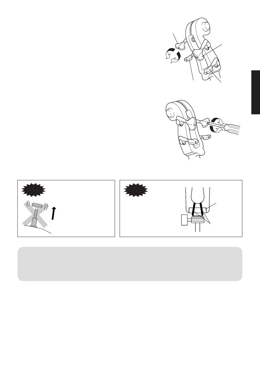
• The strings are tuned to the following pitches. The 1st
string is tuned to A, the 2nd string to D, the 3rd string to
G, and the 4th string to C.
Use a piano, tuning fork, tuner, etc., and adjust the pitch
of each string using the tuning pegs.
A
B
1st string (A)
4th string (C)
2nd string (D)
3rd string (G)
Lower
pitch
Raise
pitch
• Use the tension adjustment screw on the tuning machines to
adjust the amount of pressure required to turn the tuners.
* If the tuning machine turns with very slight pressure
→ Rotate the adjustment screw to the right (clockwise: A).
* If the tension is tight and the tuning machine is hard to turn
→ Rotate the adjustment screw to the left (counter-clock-
wise: B).
• Finally, use the adjuster to fine tune the strings.
If the adjuster is too loose,
it could produce noise
while playing.
Caution
Don’t loosen
too much.
Make sure that the Tail
Nylon is correctly po-
sitioned on top of the
Saddle.
Caution
• When the instrument is not being used, loosen the strings until the pitch drops a whole tone.
• If the instrument is not going to be used for an extended period of time, loosen the strings even more.
• Before using the instrument, make sure that the bridge is positioned vertically. Damage to the bridge
and poor sound quality may result if the bridge is not properly positioned.
Tall nylon
Saddle
06.10.4, 1:59 PMPage 9
10
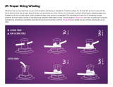
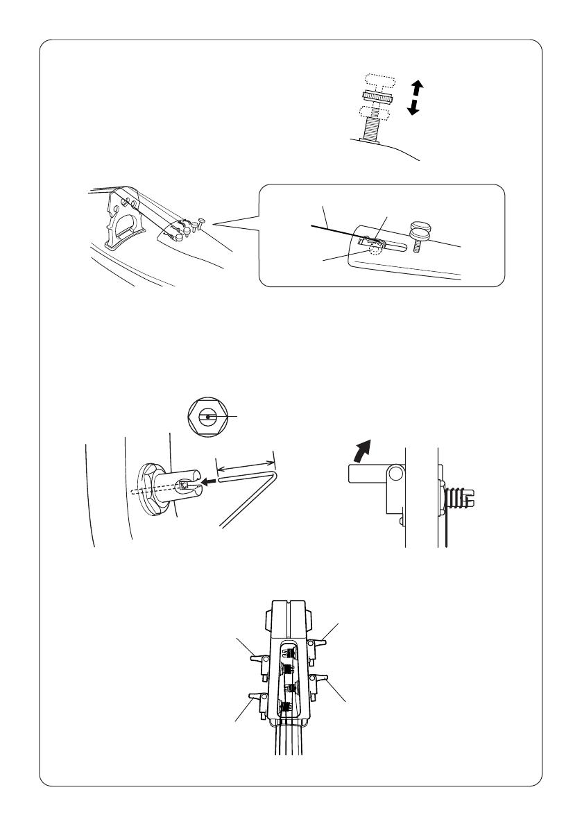
● Winding the Strings
1
Before you string the instrument, set the adjuster so that it
is in the middle of its adjustment range. (All adjusters)
2
Place the ball (on the end of the string) in the notch on the
adjuster. Make sure the ball is properly inserted in the
adjuster’s notch.
3
At a point about 2 cm from the string’s end, bend the string at a right angle and insert the end into the
hole in the tuner. While pulling the string toward the bridge to maintain string tension, turn the tuner
machine to wind the string around the tuning post. Make sure the string is wound toward the base of
the post as shown in the illustration below.
The adjuster should be
set to the middle of its
adjustment range.
1st string (A)
4th string (C)
2nd string (D)
3rd string (G)
Adjuster’s notch
String
Ball
Insert the string’s
end into this hole
Wind the string
[Looking from the front]
String
About 2 cm
06.10.4, 1:59 PMPage 10
11
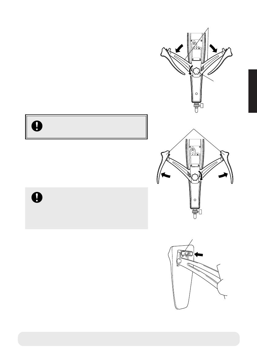
■ Setting the Knee Supports
The Silent Electric Cello is shipped with the knee sup-
ports folded.
Before playing, follow the procedure shown below to
properly set the knee supports into position.
1
Loosen the knee support lock knob (about 3 turns).
• Do not loosen the knob too much.
2
Slowly unfold the knee support arms on both sides of the
instrument until they are fully open.
• If the arm is caught and cannot be opened, loosen the
knee support lock knob a little more.
Use caution when expanding the knee support
arms. Do not pinch your hand or fingers in the
arms.
3
Tighten the knee support lock knob and make sure that the
knee support arms stay in place.
• Make sure the knee supports are firmly secured in place.
If they are loose, they may produce noise or cause the
instrument to move about while being played.
4
Slowly unfold the knee supports until they are fully open.
5
Slide the stoppers, located on the inner side of the knee sup-
ports, over the arm to lock the knee supports in place.
With this, setting of the knee supports is complete. To
fold the knee supports simply reverse the order of the
procedure shown above.
Don’t tighten the knee support lock knob unless
the knee support arms are fully opened or fully
closed. Doing so may result in damage.
Due to the design, tightening the lock knob when
the arms are closed will not lock the arms in
place.
• Do not carry the instrument by the knee supports. Always carry the instrument by the neck or body.
1
22
Knee support
lock knob
Knee support arms
5
Stopper
3
44
Knee supports
06.10.4, 1:59 PMPage 11
12
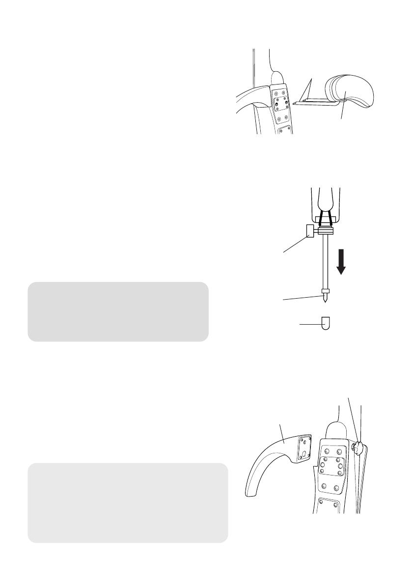
■ About the Chest Support
The chest support is used to rest the cello
against your body.
As shown in the illustration, insert the pins
on the chest support into the attaching holes
located on the back of the instrument.
■ About the End Pin
Loosen the end pin stopper, extend the end
pin to a comfortable length for playing and
firmly tighten the end pin stopper.
A rubber foot is attached to the tip of the
end pin. Removing the rubber foot exposes
the pointed end pin that can be used on ap-
propriate surfaces.
• The end pin is pointed. Please be careful when
using the exposed end pin.
• Make sure the end pin stopper is secured firmly
to prevent the instrument from slipping while you
play.
■ About the Arm Support
The Silent Electric Cello is shipped with the arm
support detached.
Hold the arm support so that its attachment plate
is parallel to the attachment position on the body.
Tighten the arm support fixing bolt and secure
the arm support to the body.
• Make sure the arm support is firmly attached. If it is
loose, it may produce noise or cause the instrument to
move about while being played.
• Do not try to remove the arm support fixing bolt from
the instrument.
• Do not carry the instrument by the arm support. Al-
ways carry the instrument by the neck or body.
Back of Silent
Electric Cello
Chest support
Pins
Rubber Foot
End Pin
End Pin
Stopper
Arm support
Arm support fixing bolt
06.10.4, 1:59 PMPage 12

13
Power Supply
The Silent Electric Cello can be operated with either battery or AC power. Al-
ways turn the power switch (OFF/ON/REV.ON) on the rear panel OFF before
making AC power connections or replacing batteries.
■ Using Batteries
1
Open the battery compartment situated on the back
of the Silent Electric Cello.
2
Insert the two batteries supplied (SUM-3 size). Take
careful note of the polarity markings as shown in
the illustration above, and insert the batteries.
3
Replace the battery compartment cover.
Slide the POWER switch to the ON position, the lamp will light green. Slide the switch to the
REV. ON position, the lamp will flash red. When battery power is low, the lamp’s color changes
to orange, the sound becomes distorted, the Reverb does not properly function, and noise
becomes audible. When one of these symptoms appears, take note of the following cautions
and replace the batteries.
• Always follow the +/– signs when inserting the batteries. Improper insertion may result in fire.
• Always replace worn batteries with a complete set of new batteries. Never mix new and old
batteries. Do not mix different types of batteries (alkaline and manganese, or batteries from different
manufacturers, or different types by the same manufacturer). Doing so may result in fire.
■ Supplying AC Power
The AC adaptor is an optional accessory, please purchase a PA-3C power adaptor.
1
Plug the adaptor’s DC output cable into the Silent Electric Cello’s DC IN 9-12V jack located on the back
of the instrument, making sure the plug is firmly inserted into the jack.
2
Plug the AC adaptor into a convenient wall AC power socket.
• Battery power is automatically disconnected when the AC adaptor is connected.
• When the AC adaptor is used, the batteries may leak. To prevent leakage we recommend that you re-
move the batteries from the instrument. When the AC adapter is used.
• When using an AC adaptor, make sure you use only the appointed compatible adaptor. The use of an
incompatible adaptor may result in damage to the instrument or cause fire, etc. Please use with caution.
• To prevent possible damage to the unit due to battery leakage and unnecessary power drain, remove
the batteries from the unit when it is not going to be used for an extended period of time.
Bij dit produkt zijn batterijen geleverd.
Wanneer deze leeg zijn, moet u ze niet
weggooien maar inleveren als KCA.
Battery compartment
cover
* For customers in the Netherlands
SUM-3 size
battery x2
06.10.4, 1:59 PMPage 13
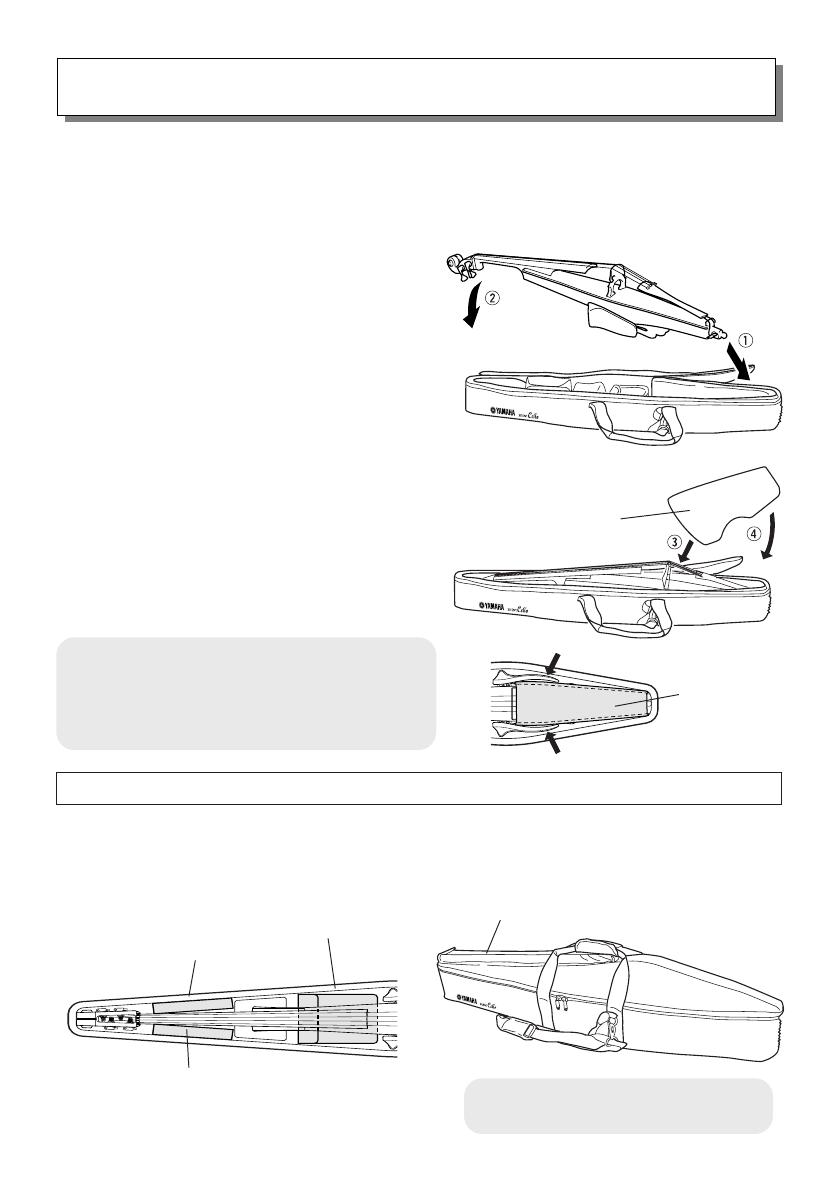
14
About the Supplied Soft Case
● Placing the cello in the case
1
Fold up the knee supports, and remove the chest and
arm supports from the Silent Electric Cello.
Slide the end pin all the way into the instrument, and
tighten the end pin stopper to secure.
2
First place the end pin end of the instrument into the
soft case q, followed by the head end of the instru-
ment w.
● Setting the Protector
1
Starting with the bridge side of the protector, slide it
at an angle between the knee supports and case e.
2
Gently push the end pin end of the protector into place
r.
● The Storage Pockets
Bow pocket
Arm support, etc.
Chest support, etc.
Cable, Headphones, etc.
Protector
Protector
* The protector does not guarantee against damage to parts such as the bridge, etc.
• The protector is designed to protect the instrument
against light shocks while the instrument is being
carried. Never expose the protector to shocks such
as placing the case with the protector facing down,
placing objects on top of or hitting the protector.
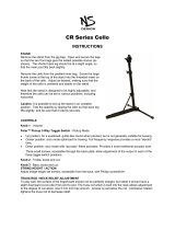
The supplied soft case is designed specifically for use with the SVC210 Silent
Electric Cello. Attaching the protector (included in the case) allows storage and
transport of the instrument with its bridge attached.
• When storing the bow in the bow pocket,
always place the bow in its case.
06.10.4, 1:59 PMPage 14

15
Specifications
Neck Maple
Body Spruce/Maple
Fingerboard Ebony
Bridge Maple (Aubert)
Knee Supports/Arm Support Beech
Tuning Pegs Worm Gear Type
Tail Piece Adjuster 4 pieces (Wittner)
Strings Ball-end type (Helicore)
Sensor Piezo pick-up
Connectors/Controls • Headphone Output
• AUX IN (w/Volume Control)
• LINE OUT
• Volume
• Reverb Switch (RM/HL1/HL2)
Power • POWER Switch (OFF/ON/REV. ON)
• SUM-3 size battery x2
Battery Life (Continuous Use) Using Manganese batteries
• Without Reverb (POWER Switch “ON”)
approximately 10 hours
• With Reverb (POWER Switch “REV. ON”)
approximately 3 hours
Using Alkaline batteries
• Without Reverb (POWER Switch “ON”)
approximately 25 hours
• With Reverb (POWER Switch “REV. ON”)
approximately 9 hours
String Length 690 mm (27-3/8”)
Dimensions (setup for playing with the chest support attached)
1,251 (L) x 438 (W) x 243 (H) mm
49-1/4” (L) x 17-1/4” (W) x 9-9/16” (H)
Weight
(with batteries and
chest
support)
3.9kg (8 lbs. 2 oz.)
* Design and specifications are subject to change without notice.
06.10.4, 1:59 PMPage 15
/