


First Edition, April 2003, SVE-1-101(B) (out of print)
Second Edition, July 2003, SVE-1-101(C) (out of print)
Third Edition, June 2004, SVE-1-101(D) (out of print)
Fourth Edition, December 2006, SVE-1-101(E) (out of print)
Fifth Edition, October 2008, SVE-1-101(F)
All Rights Reserved, Copyright © 2003, 2008, Hitachi, Ltd.
The contents of this publication may be revised without prior notice.
No part of this publication may be reproduced in any form or by any means without permission
in writing from the publisher.
Printed in Japan.
BI-NR-HS<IC-IC> (FL-MW20, AI8.0)

SAFETY PRECAUTIONS
Be sure to read this manual and all other attached documents carefully before installing,
operating inspecting or conducting maintenance on this unit. Always use this unit properly.
Be sure to carefully read the information about the device, the safety information and precautions
before using this unit. Be sure that the person(s) responsible for maintenance receives and
understands this manual completely.
This manual divides the safety precautions into DANGERs and CAUTIONs.
: Failure to observe these warnings may result in death or serious injury.
: Failure to observe these cautions may result in injury or property
damage.
Failure to observe any may lead to serious consequences.
All of these DANGERs and CAUTIONs provide very important precautions and should
always be observed.
Additional safety symbols representing a prohibition or a requirement are as follows:
: Prohibition. For example, “Do not disassemble” is represented by:
: Requirement. For example, if a ground is required, the following will be shown:
DANGER
CAUTION
CAUTION

1. Installation Precautions
DANGER
If an emergency stop circuit, interlock circuit, or similar circuit is to be
formulated, it must be positioned external to this module. If you do not
observe this precaution, equipment damage or accident may occur when this
module becomes defective.
Ensure that the employed external power source has overvoltage and
overcurrent protection functions.
The external power source voltage may create an electric shock hazard. If
you disconnect/connect the module or cable with the power supply switched
on, you may inadvertently touch a power supply terminal and receive an
electric shock or the equipment may become damaged due to short circuit or
noise. Switch off the power supply before disconnecting/connecting the
module or cable.
CAUTION
Use the module in an environment specified in the catalog and manual.
If you use the module in an environment where the module is subjected to high
temperature, high humidity, dust, corrosive gas, vibration, or impact, a risk of
electric shock, fire, or malfunction may result.
Observe the installation procedure stated in the manual.
If the module is improperly installed, it may drop, become defective, or
malfunction.
Do not allow wire cuttings or other foreign matter to enter the module.
The entry of foreign matter in the module may result in a fire or cause the
module to become defective or malfunction.
When the module is to be positioned at a location where it may become wet
with water, place it within a drip-proof enclosure to prevent it from becoming
defective.
The module may become defective due to a high temperature, which may
result from heat dissipation failure. It may also malfunction due to
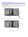
electromagnetic interference from nearby equipment. For heat dissipation
and electromagnetic radiation minimization, provide the specified clearances
among the module, its enclosure, and neighboring equipment.

CAUTION
The degree of temperature rise varies depending on how the module is
mounted. The mounting intervals specified in the manual should be used as
a guide only. While a test run is conducted after completion of mounting,
measure the temperature near the module to check whether it is within the
specified range. If the measured temperature is beyond the specified range,
increase the mounting intervals or provide forced air cooling with a cooling fan.
Dust or other foreign matter might accumulate on the connector, resulting in
poor contact. Immediately after the module is unpacked, perform the
mounting and wiring procedures.
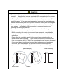
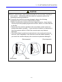
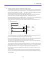
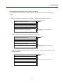
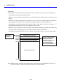
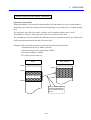
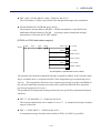
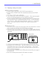
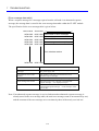
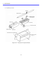
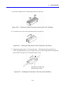
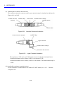
To prevent the module from being damaged, observe the following precautions
when you mount or demount the module:
• Before mounting the module to the mount base connector, check that the
connector pins are properly aligned and not bent, broken, or soiled with dirt
or the like.
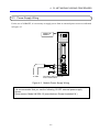
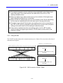
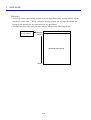
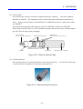
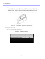
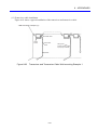
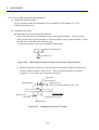
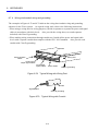
• Ensure that the module is parallel to the mount base vertical surface as
shown below when mounting. If you connect a module to or disconnect it
from its connector while it is tilted, the connector pins may become damaged.
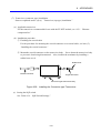
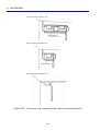
• If the mount base is positioned overhead due to the employed enclosure
structure, use a stepladder or the like and mount the module squarely. If
you mount the module obliquely, the connector may become damaged.
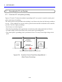
[Bad example] [Good example]
Mount base Module

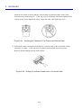
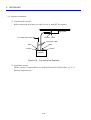
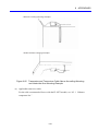
REQUIREMENT
Fasten the mount base to a vertical surface. Fastening the mount base to a
horizontal surface lessens the heat dissipation effects and allows the
temperature to rise, thereby rendering the module defective or incurring
component parts deterioration.
Before installing the module, discharge any static buildup from your body
because static electricity may render the module defective.
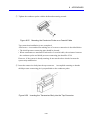
Properly tighten the screws. If they are inadequately tightened, malfunction,
smoke emission, or combustion may occur.
PROHIBITION
Do not disassemble or modify the module. Failure to observe this precaution
may result in a fire or cause the module to become defective or malfunction.

2. Wiring Precautions
DANGER
Electric shock hazards exist so that you might suffer burns or become
electrocuted. Further, the system might malfunction due to noise interference.
Therefore, ground the line ground (LG), frame ground (FG), and shield wire
(SHD).
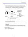
REQUIREMENT
Insulate the mount base from the enclosure. To keep the mount base
insulated, avoid removing the insulation sheets that are supplied with the
mount base.
The LG is a ground terminal for power supply noise. The FG and SHD are
ground terminals for the noise in the remote I/O, communication module and
other external interface lines. To avoid interference between the ground
terminals, separately ground the LG and FG.
CAUTION
If the input voltage for the power supply module is within the specified range
but close to the upper or lower limit, you should conclude that an input power
problem exists, and ask the power supply facility manager to conduct an
inspection.
Be sure that the power source for supplying power to various modules is rated
as specified. The use of a differently rated power source may cause a risk of
fire.
Only qualified personnel should be allowed to make cable connections.
Incorrect wiring connections may cause a risk of fire, malfunction, or electric
shock.

REQUIREMENT
To provide protection against short circuit, furnish the external power source
with a fuse or circuit protector. Ensure that the employed circuit protector is
rated as specified.
Before supplying power to the equipment, thoroughly check the wiring
connections.
Before making power supply wiring connections, make sure that no voltage is
applied to the power cable. Immediately after completion of power supply
wiring, be sure to install the terminal cover.
Ensure that the communication, power supply, motive power, and other cables
are routed apart from each other. It is essential that the inverter, motor,
power regulator, and other motive power cables be routed at least 300 mm
away from the other types of cables. Also, be sure that the communication
and motive power cables are routed within separate conduits.
PROHIBITION
To avoid noise-induced malfunction, do not bundle the 100 VAC/100 VDC wiring
and network cable together, but route them at least 100 mm away from each
other.

3. Operating Precautions
DANGER
While the power is ON, do not touch any terminal, otherwise you may receive an
electric shock.
CAUTION
Before changing the program, generating a forced output, or performing the
RUN, STOP, or like procedure during an operation, thoroughly verify the safety
because the use of an incorrect procedure may cause equipment damage or
other accident.
When you switch on the power supply, follow the specified sequence. Failure
to follow the specified sequence may cause equipment damage or other
accident.
Do not use a transceiver, cellular phone, or similar device near the module
because module malfunction or system failure may occur due to noise.
To avoid malfunction, ensure that the power supply is switched on and off at
intervals of longer than 1 second.
Before constructing a system, creating a program, or performing a similar
procedure, thoroughly read this manual to become familiar with the contained
instructions and precautions. If you perform any incorrect procedure, the
system may malfunction.
Store this manual at a predetermined place where it can readily be referred to
whenever it is needed.
If you have any doubt or question about the contents of this manual, contact
your local source.

CAUTION
Hitachi cannot be responsible for accidents or losses resulting from a
customer’s misuse.
If the software supplied by Hitachi is modified for use, Hitachi cannot be
responsible for accidents or losses resulting from such modification.
Hitachi cannot be responsible for reliability if you use software other than
supplied from Hitachi.
Back up files on a daily basis. You might lose the contents of files due, for
instance, to a file unit failure, power failure during a file access, or operating
error. To provide against such contingencies, back up files according to an
appropriate plan.
When this product is to be discarded, ask a qualified industrial waste disposal
contractor to properly dispose of it.
Install a protective circuit or a safety circuit externally so as to completely
secure the safety of the system to be used even if our product causes a failure
or malfunctions or a fault is found in the program. Design the system so as to
take full safety precautions against an accident that may result in injury, death
or serious disaster.
Configure an emergency stop circuit, interlock circuit, etc. outside the PLC.
Otherwise, PLC failure may cause machine damage or an accident.

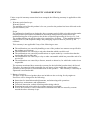
WARRANTY AND SERVICING
Unless a special warranty contract has been arranged, the following warranty is applicable to this
product.
1. Warranty period and scope
Warranty period
The warranty period for this product is for one year after the product has been delivered to the
specified delivery site.
Scope
If a malfunction should occur during the above warranty period while using this product under
normal product specification conditions as described in this manual, please deliver the
malfunctioning part of the product to the dealer or Hitachi Engineering & Services Co., Ltd.
The malfunctioning part will be replaced or repaired free of charge. If the malfunctioning is
shipped, however, the shipment charge and packaging expenses must be paid for by the
customer.
This warranty is not applicable if any of the following are true.
The malfunction was caused by handling or use of the product in a manner not specified in
the product specifications.
The malfunction was caused by a unit other than that which was delivered.
The malfunction was caused by modifications or repairs made by a vendor other than the
vendor that delivered the unit.
The malfunction was caused by a relay or other consumable which has passed the end of its
service life.
The malfunction was caused by a disaster, natural or otherwise, for which the vendor is not
responsible.
The warranty mentioned here means the warranty for the individual product that is delivered.
Therefore, we cannot be held responsible for any losses or lost profits that result from the
operation of this product or from malfunctions of this product. This warranty is valid only in
Japan and is not transferable.
2. Range of services
The price of the delivered product does not include on-site servicing fees by engineers.
Extra fees will be charged for the following:
Instruction for installation and adjustments, and witnessing trial operations.
Inspections, maintenance and adjustments.
Technical instruction, technical training and training schools.
Examinations and repairs after the warranty period is concluded.
Even if the warranty is valid, examination of malfunctions that are caused by reasons
outside the above warranty scope.

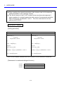
This manual provides information for the following hardware and program products:
<Hardware product>
FL.NET (LQE500/LQE502)
<Program products>
S-7890-30 “FL.NET SYSTEM” 07-03
S-7895-30 “S10V FL.NET SYSTEM” 01-01
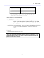
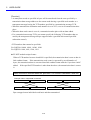
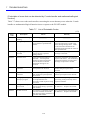
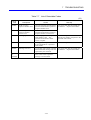
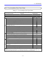
<Changes added to this manual>
Description of added changes Page
Subsection 6.1.1, “Replacing or adding on the module” is newly added. 6-3
In addition to the above changes, all the unclear descriptions and typographical errors found are also
corrected without prior notice.

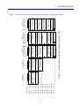
Revision record
Revision No. Revision Record (revision details and reason for revision) Month, Year Remarks
B First Edition April 2003
F Subsection 6.1.1, “Replacing or adding on the module”
is newly added.
October 2008

i
PREFACE
Thank you for purchasing the FL.NET module, which is an option for use with the S10mini/S10V.
This manual, named “USER’S MANUAL OPTION FL.NET,” describes how to use the FL.NET
module. For proper use of the CPU link module, it is requested that you thoroughly read this manual.
The S10mini and S10Vproducts are available in two types: standard model and environmentally
resistant model. The environmentally resistant model has thicker platings and coatings than those for
the standard model.
The model number of the environmentally resistant model is marked by adding the suffix “-Z” to the
model number of the standard model.
(Example) Standard model: LQE500, LQE502
Environmentally resistant model: LQE500-Z, LQE502-Z
This manual is applicable to both the standard model and environmentally resistant models.
Although the descriptions contained in this manual are based on the standard model, follow the
instructions set forth in this manual for proper use of the product even if you use the environmentally
resistant model.
<Limitation of LQE500>
When mounting S10V, FL.NET module (LQE500) before Module Rev. B (Ver-Rev: 0002-0000)
doesn’t provide for message communication function (neither do C mode handler and
mathematical/logical function), but provides for cyclic communication function applying common
memory area. Utilizing message communication function in combination with S10V, you should
use the module after Module Rev.C (Ver-Rev: 0003-0000).
Moreover, the above-mentioned Ver-Rev is a micro program Ver-Rev of FL.NET module which is
shown on “Module List” of S10V BASE SYSTEM.
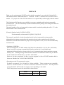
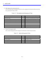
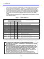
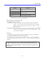
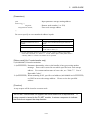
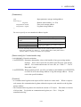
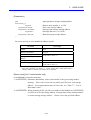
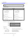
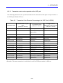
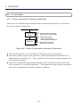
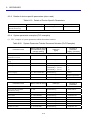
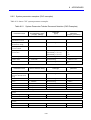
<Precautions on the FL-net protocol version>
For the FL-net protocol, Ver. 1.00 and Ver. 2.00 are available. These versions are not compatible
and a Ver. 100 device and a Ver. 2.00 device cannot be connected to each other. Note the protocol
version that the FL.NET module can support varies depending on the model.
The FL-net protocol version for each model is shown below.
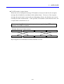
Model LQE500 LQE502
FL-net protocol version Ver. 1.00 Ver. 2.00

ii
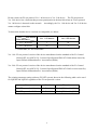
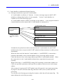
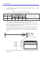
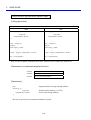
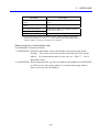
Do not connect an FL-net protocol Ver. 1.00 device to a Ver. 2.00 device. The FL-net protocol
Ver. 2.00 device has a function that prevents participation in the data link when an FL-net protocol
Ver. 100 device is detected on the network. Accordingly, the Ver. 1.00 device and Ver. 2.00 device
cannot configure a data link.
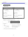
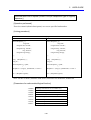
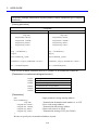
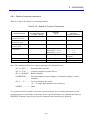
To determine whether device versions are compatible, see below.
Self-device
Other device
Ver. 1.00 device Ver. 2.00 device
Ver. 1.00 device √ nc
Ver. 2.00 device nc √
√: Connectable, nc: Not connectable
Ver. 1.00: FL-net protocol version of the device manufactured on the standard of the FA Control
Network [FL-net (OPCN-2)] - Protocol Specification JEM 1479 2000-edition issued by
Japan Electrical Manufacturers’ Association (JEMA)
Ver. 2.00: FL-net protocol version of the device manufactured on the standard of the FA Control
Network [FL-net (OPCN-2)] - Protocol Specification JEM 1479 2002-revision issued by
Japan Electrical Manufacturers’ Association (JEMA)
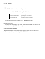
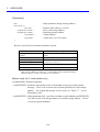
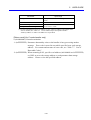
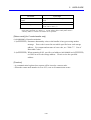
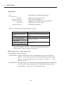
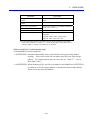
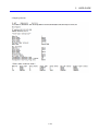
The existing parameter setting software (FL.NET system) shown in the following table can be used
for LQE500 and LQE502 regardless of the FL-net protocol version.
Name Model Remarks
FL.NET system for S10mini S-7890-30J For LQE500 and LQE502
FL.NET system for S10V S-7895-30J For LQE500 and LQE502

iii
<Trademarks>
• Microsoft® Windows® operating system, Microsoft® Windows® 95 operating system,
Microsoft® Windows® 98 operating system, Microsoft® Windows® 2000 operating system,
Microsoft® Windows® XP operating system are registered trademarks of Microsoft Corporation in
the United States and/or other countries.
• Ethernet® is registered trademark of Xerox, Corp.
<Note for storage capacity calculations>
Memory capacities and requirements, file sizes and storage requirements, etc. must be calculated
according to the formula 2
n
. The following examples show the results of such calculations by 2
n
(to the right of the equals signs).
1 KB (kilobyte) = 1,024 bytes
1 MB (megabyte) = 1,048,576 bytes
1 GB (gigabyte) = 1,073,741,824 bytes
As for disk capacities, they must be calculated using the formula 10
n
. Listed below are the
results of calculating the above example capacities using 10
n
in place of 2
n
.
1 KB (kilobyte) = 1,000 bytes
1 MB (megabyte) = 1,000
2
bytes
1 GB (gigabyte) = 1,000
3
bytes

iv
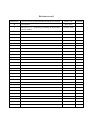
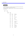
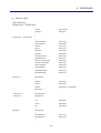
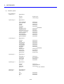
CONTENTS
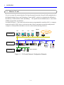
1 OVERVIEW ........................................................................................................................ 1-1
1.1 What is FL-net ............................................................................................................... 1-2
1.2 FL-net Features ................................................................................................................ 1-3
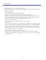
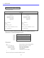
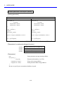
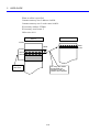
2 FL.NET MODULE.............................................................................................................. 2-1
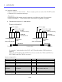
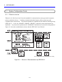
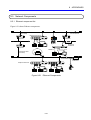
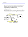
2.1 System Configuration ...................................................................................................... 2-2
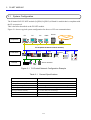
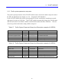
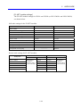
2.1.1 Functionality and performance specifications........................................................ 2-3
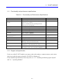
2.1.2 Support tool specification ...................................................................................... 2-3
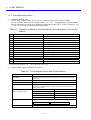
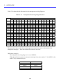
2.1.3 Link data specifications.......................................................................................... 2-4
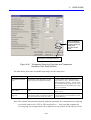
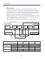
2.1.4 Link parameter setup area ...................................................................................... 2-6
2.1.5 Profile system parameter setup area....................................................................... 2-7
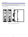
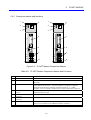
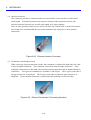
2.2 FL.NET Module Component Names and Functions........................................................ 2-8
2.2.1 External views........................................................................................................ 2-8
2.2.2 Component names and functions ........................................................................... 2-9
3 FL.NET MODULE INSTALLATION ................................................................................ 3-1
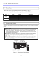
3.1 Mount Base ...................................................................................................................... 3-2
3.2 Mounting the Module ...................................................................................................... 3-2
3.3 Setting the Module Number Selector Switch................................................................... 3-4
4 FL.NET MODULE WIRING PROCEDURES ................................................................... 4-1
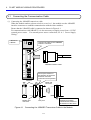
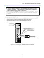
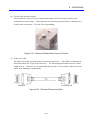
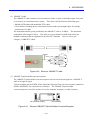
4.1 Connecting the Communication Cable .......................................................................... 4-2
4.2 Applicable Communication Cables ................................................................................. 4-4
4.3 Power Supply Wiring....................................................................................................... 4-5
4.4 Ground Wiring ................................................................................................................. 4-6
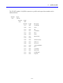
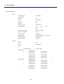
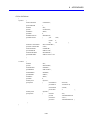
5 USER GUIDE...................................................................................................................... 5-1
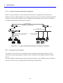
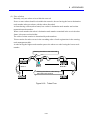
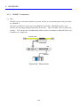
5.1 Ethernet ............................................................................................................................ 5-2
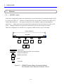
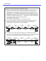
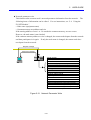
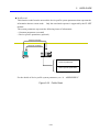
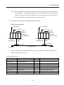
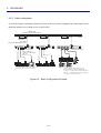
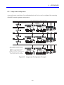
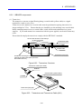
5.1.1 10BASE5 system ................................................................................................... 5-2
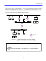
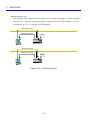
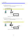
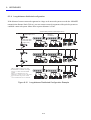
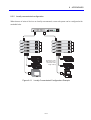
5.1.2 10BASE-T system.................................................................................................. 5-7
5.2 FL-net............................................................................................................................. 5-10
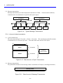
5.2.1 FL-net overview ................................................................................................... 5-10
5.2.2 Connection capacity and node numbers............................................................... 5-12
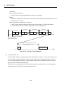
5.2.3 Supported data communications .......................................................................... 5-13

v
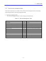
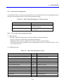
5.2.4 Amount of data transmission............................................................................... 5-14
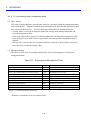
5.2.5 Transfer cycle and monitoring............................................................................. 5-15
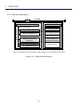
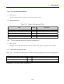
5.2.6 Data area and memory......................................................................................... 5-16
5.2.7 Communication management tables.................................................................... 5-17
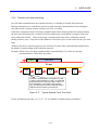
5.2.8 Cyclic transmission and area ............................................................................... 5-19
5.2.9 Message transmission.......................................................................................... 5-24
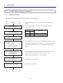
5.3 FL.NET Module Setup Procedures ............................................................................... 5-36
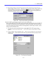
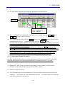
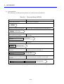
5.3.1 Startup procedure................................................................................................. 5-36
5.3.2 Module installation and switch setup .................................................................. 5-38
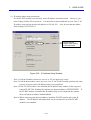
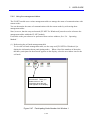
5.3.3 Tool connection procedure.................................................................................. 5-38
5.3.4 Tool startup procedure......................................................................................... 5-38
5.4 Using the FL.NET Module............................................................................................ 5-39
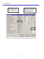
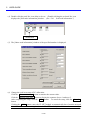
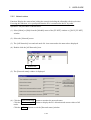
5.4.1 Link parameter setup procedure .......................................................................... 5-39
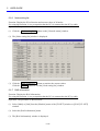
5.4.2 CPU or LPU memory allocation procedure......................................................... 5-42
5.4.3 Using bit data....................................................................................................... 5-51
5.4.4 Using word data................................................................................................... 5-52
5.4.5 Using message communications.......................................................................... 5-52
5.4.6 Using the management tables............................................................................ 5-113
5.4.7 FL.NET module communication performance.................................................. 5-120
5.4.8 Using the communication log............................................................................ 5-126
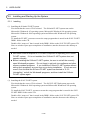
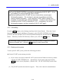
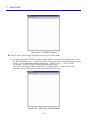
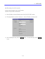
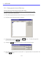
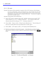
5.5 Installing and Starting Up the System ......................................................................... 5-128
5.5.1 Installing ............................................................................................................ 5-128
5.5.2 Uninstalling ....................................................................................................... 5-129
5.5.3 Starting up the system ....................................................................................... 5-129
5.5.4 Changing connections ....................................................................................... 5-132
5.5.5 Selecting an edition file..................................................................................... 5-133
5.5.6 Closing the system............................................................................................. 5-134
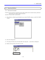
5.6 Operating Method........................................................................................................ 5-135
5.6.1 Self-node information........................................................................................ 5-135
5.6.2 Other nodes display ........................................................................................... 5-137
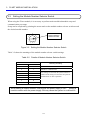
5.6.3 Other nodes reception setup .............................................................................. 5-138
5.6.4 Joining other nodes information........................................................................ 5-139
5.6.5 Network status................................................................................................... 5-141
5.6.6 Node setting list................................................................................................. 5-142
5.6.7 RAS information ............................................................................................... 5-142
5.6.8 Saving setups..................................................................................................... 5-143

vi
5.6.9 Sending setups.................................................................................................... 5-144
5.6.10 Setup IP address ................................................................................................. 5-146
5.6.11 Entering operation function (S10mini only) ...................................................... 5-148
5.6.12 Printing............................................................................................................... 5-150
5.6.13 CSV output......................................................................................................... 5-152
6 MAINTENANCE ................................................................................................................ 6-1
6.1 Maintenance and Inspection............................................................................................. 6-2
6.1.1 Replacing or adding on the module ....................................................................... 6-3
7 TROUBLESHOOTING....................................................................................................... 7-1
7.1 Trouble Detection and Solution ....................................................................................... 7-2
7.2 Network Problems and Repairing.................................................................................... 7-3
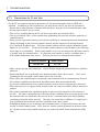
7.3 Precautions for FL-net Use ............................................................................................ 7-6
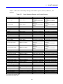
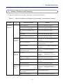
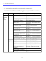
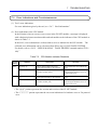
7.4 Error Indications and Countermeasures ........................................................................... 7-7
8 APPENDIXES..................................................................................................................... 8-1
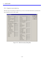
8.1 System Configuration Guide .......................................................................................... 8-2
8.1.1 Ethernet overview .................................................................................................. 8-2
8.1.2 10BASE5 specifications ........................................................................................ 8-3
8.1.3 10BASE-T specifications....................................................................................... 8-4
8.1.4 Other Ethernet specifications ................................................................................. 8-5
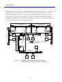
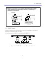
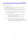
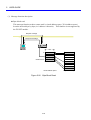
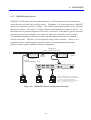
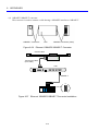
8.2 System Configuration Examples...................................................................................... 8-7
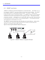
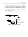
8.2.1 Small-scale configuration....................................................................................... 8-7
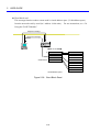
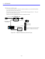
8.2.2 Basic configuration ................................................................................................ 8-8
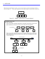
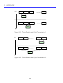
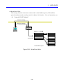
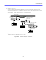
8.2.3 Large-scale configuration....................................................................................... 8-9
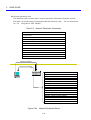
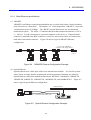
8.2.4 Long-distance distributed configuration .............................................................. 8-10
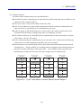
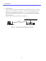
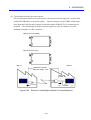
8.2.5 Locally concentrated configuration...................................................................... 8-11
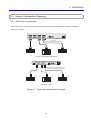
8.2.6 Locally and widely distributed configuration....................................................... 8-12
8.2.7 Concept of FL-net system .................................................................................... 8-12
8.2.8 Differences between general-purpose Ethernet and FL-net ................................. 8-13
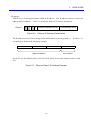
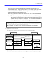
8.3 Network System Definitions .......................................................................................... 8-14
8.3.1 Standard compliance of communication protocol................................................ 8-14
8.3.2 Communication protocol hierarchical structure................................................... 8-14
8.3.3 FL-net physical layer............................................................................................ 8-15
8.3.4 IP address ............................................................................................................. 8-15
Page is loading ...
Page is loading ...
Page is loading ...
Page is loading ...
Page is loading ...
Page is loading ...
Page is loading ...
Page is loading ...
Page is loading ...
Page is loading ...
Page is loading ...
Page is loading ...
Page is loading ...
Page is loading ...
Page is loading ...
Page is loading ...
Page is loading ...
Page is loading ...
Page is loading ...
Page is loading ...
Page is loading ...
Page is loading ...
Page is loading ...
Page is loading ...
Page is loading ...
Page is loading ...
Page is loading ...
Page is loading ...
Page is loading ...
Page is loading ...
Page is loading ...
Page is loading ...
Page is loading ...
Page is loading ...
Page is loading ...
Page is loading ...
Page is loading ...
Page is loading ...
Page is loading ...
Page is loading ...
Page is loading ...
Page is loading ...
Page is loading ...
Page is loading ...
Page is loading ...
Page is loading ...
Page is loading ...
Page is loading ...
Page is loading ...
Page is loading ...
Page is loading ...
Page is loading ...
Page is loading ...
Page is loading ...
Page is loading ...
Page is loading ...
Page is loading ...
Page is loading ...
Page is loading ...
Page is loading ...
Page is loading ...
Page is loading ...
Page is loading ...
Page is loading ...
Page is loading ...
Page is loading ...
Page is loading ...
Page is loading ...
Page is loading ...
Page is loading ...
Page is loading ...
Page is loading ...
Page is loading ...
Page is loading ...
Page is loading ...
Page is loading ...
Page is loading ...
Page is loading ...
Page is loading ...
Page is loading ...
Page is loading ...
Page is loading ...
Page is loading ...
Page is loading ...
Page is loading ...
Page is loading ...
Page is loading ...
Page is loading ...
Page is loading ...
Page is loading ...
Page is loading ...
Page is loading ...
Page is loading ...
Page is loading ...
Page is loading ...
Page is loading ...
Page is loading ...
Page is loading ...
Page is loading ...
Page is loading ...
Page is loading ...
Page is loading ...
Page is loading ...
Page is loading ...
Page is loading ...
Page is loading ...
Page is loading ...
Page is loading ...
Page is loading ...
Page is loading ...
Page is loading ...
Page is loading ...
Page is loading ...
Page is loading ...
Page is loading ...
Page is loading ...
Page is loading ...
Page is loading ...
Page is loading ...
Page is loading ...
Page is loading ...
Page is loading ...
Page is loading ...
Page is loading ...
Page is loading ...
Page is loading ...
Page is loading ...
Page is loading ...
Page is loading ...
Page is loading ...
Page is loading ...
Page is loading ...
Page is loading ...
Page is loading ...
Page is loading ...
Page is loading ...
Page is loading ...
Page is loading ...
Page is loading ...
Page is loading ...
Page is loading ...
Page is loading ...
Page is loading ...
Page is loading ...
Page is loading ...
Page is loading ...
Page is loading ...
Page is loading ...
Page is loading ...
Page is loading ...
Page is loading ...
Page is loading ...
Page is loading ...
Page is loading ...
Page is loading ...
Page is loading ...
Page is loading ...
Page is loading ...
Page is loading ...
Page is loading ...
Page is loading ...
Page is loading ...
Page is loading ...
Page is loading ...
Page is loading ...
Page is loading ...
Page is loading ...
Page is loading ...
Page is loading ...
Page is loading ...
Page is loading ...
Page is loading ...
Page is loading ...
Page is loading ...
Page is loading ...
Page is loading ...
Page is loading ...
Page is loading ...
Page is loading ...
Page is loading ...
Page is loading ...
Page is loading ...
Page is loading ...
Page is loading ...
Page is loading ...
Page is loading ...
Page is loading ...
Page is loading ...
Page is loading ...
Page is loading ...
Page is loading ...
Page is loading ...
Page is loading ...
Page is loading ...
Page is loading ...
Page is loading ...
Page is loading ...
Page is loading ...
Page is loading ...
Page is loading ...
Page is loading ...
Page is loading ...
Page is loading ...
Page is loading ...
Page is loading ...
Page is loading ...
Page is loading ...
Page is loading ...
Page is loading ...
Page is loading ...
Page is loading ...
Page is loading ...
Page is loading ...
Page is loading ...
Page is loading ...
Page is loading ...
Page is loading ...
Page is loading ...
Page is loading ...
Page is loading ...
Page is loading ...
Page is loading ...
Page is loading ...
Page is loading ...
Page is loading ...
Page is loading ...
Page is loading ...
Page is loading ...
Page is loading ...
Page is loading ...
Page is loading ...
Page is loading ...
Page is loading ...
Page is loading ...
Page is loading ...
Page is loading ...
Page is loading ...
Page is loading ...
Page is loading ...
Page is loading ...
Page is loading ...
Page is loading ...
Page is loading ...
Page is loading ...
Page is loading ...
Page is loading ...
Page is loading ...
Page is loading ...
Page is loading ...
Page is loading ...
Page is loading ...
Page is loading ...
Page is loading ...
Page is loading ...
Page is loading ...
Page is loading ...
Page is loading ...
Page is loading ...
Page is loading ...
Page is loading ...
Page is loading ...
Page is loading ...
Page is loading ...
Page is loading ...
Page is loading ...
Page is loading ...
Page is loading ...
Page is loading ...
Page is loading ...
Page is loading ...
Page is loading ...
Page is loading ...
Page is loading ...
Page is loading ...
Page is loading ...
Page is loading ...
Page is loading ...
Page is loading ...
Page is loading ...
Page is loading ...
Page is loading ...
Page is loading ...
Page is loading ...
Page is loading ...
Page is loading ...
Page is loading ...
Page is loading ...
-
 1
1
-
 2
2
-
 3
3
-
 4
4
-
 5
5
-
 6
6
-
 7
7
-
 8
8
-
 9
9
-
 10
10
-
 11
11
-
 12
12
-
 13
13
-
 14
14
-
 15
15
-
 16
16
-
 17
17
-
 18
18
-
 19
19
-
 20
20
-
 21
21
-
 22
22
-
 23
23
-
 24
24
-
 25
25
-
 26
26
-
 27
27
-
 28
28
-
 29
29
-
 30
30
-
 31
31
-
 32
32
-
 33
33
-
 34
34
-
 35
35
-
 36
36
-
 37
37
-
 38
38
-
 39
39
-
 40
40
-
 41
41
-
 42
42
-
 43
43
-
 44
44
-
 45
45
-
 46
46
-
 47
47
-
 48
48
-
 49
49
-
 50
50
-
 51
51
-
 52
52
-
 53
53
-
 54
54
-
 55
55
-
 56
56
-
 57
57
-
 58
58
-
 59
59
-
 60
60
-
 61
61
-
 62
62
-
 63
63
-
 64
64
-
 65
65
-
 66
66
-
 67
67
-
 68
68
-
 69
69
-
 70
70
-
 71
71
-
 72
72
-
 73
73
-
 74
74
-
 75
75
-
 76
76
-
 77
77
-
 78
78
-
 79
79
-
 80
80
-
 81
81
-
 82
82
-
 83
83
-
 84
84
-
 85
85
-
 86
86
-
 87
87
-
 88
88
-
 89
89
-
 90
90
-
 91
91
-
 92
92
-
 93
93
-
 94
94
-
 95
95
-
 96
96
-
 97
97
-
 98
98
-
 99
99
-
 100
100
-
 101
101
-
 102
102
-
 103
103
-
 104
104
-
 105
105
-
 106
106
-
 107
107
-
 108
108
-
 109
109
-
 110
110
-
 111
111
-
 112
112
-
 113
113
-
 114
114
-
 115
115
-
 116
116
-
 117
117
-
 118
118
-
 119
119
-
 120
120
-
 121
121
-
 122
122
-
 123
123
-
 124
124
-
 125
125
-
 126
126
-
 127
127
-
 128
128
-
 129
129
-
 130
130
-
 131
131
-
 132
132
-
 133
133
-
 134
134
-
 135
135
-
 136
136
-
 137
137
-
 138
138
-
 139
139
-
 140
140
-
 141
141
-
 142
142
-
 143
143
-
 144
144
-
 145
145
-
 146
146
-
 147
147
-
 148
148
-
 149
149
-
 150
150
-
 151
151
-
 152
152
-
 153
153
-
 154
154
-
 155
155
-
 156
156
-
 157
157
-
 158
158
-
 159
159
-
 160
160
-
 161
161
-
 162
162
-
 163
163
-
 164
164
-
 165
165
-
 166
166
-
 167
167
-
 168
168
-
 169
169
-
 170
170
-
 171
171
-
 172
172
-
 173
173
-
 174
174
-
 175
175
-
 176
176
-
 177
177
-
 178
178
-
 179
179
-
 180
180
-
 181
181
-
 182
182
-
 183
183
-
 184
184
-
 185
185
-
 186
186
-
 187
187
-
 188
188
-
 189
189
-
 190
190
-
 191
191
-
 192
192
-
 193
193
-
 194
194
-
 195
195
-
 196
196
-
 197
197
-
 198
198
-
 199
199
-
 200
200
-
 201
201
-
 202
202
-
 203
203
-
 204
204
-
 205
205
-
 206
206
-
 207
207
-
 208
208
-
 209
209
-
 210
210
-
 211
211
-
 212
212
-
 213
213
-
 214
214
-
 215
215
-
 216
216
-
 217
217
-
 218
218
-
 219
219
-
 220
220
-
 221
221
-
 222
222
-
 223
223
-
 224
224
-
 225
225
-
 226
226
-
 227
227
-
 228
228
-
 229
229
-
 230
230
-
 231
231
-
 232
232
-
 233
233
-
 234
234
-
 235
235
-
 236
236
-
 237
237
-
 238
238
-
 239
239
-
 240
240
-
 241
241
-
 242
242
-
 243
243
-
 244
244
-
 245
245
-
 246
246
-
 247
247
-
 248
248
-
 249
249
-
 250
250
-
 251
251
-
 252
252
-
 253
253
-
 254
254
-
 255
255
-
 256
256
-
 257
257
-
 258
258
-
 259
259
-
 260
260
-
 261
261
-
 262
262
-
 263
263
-
 264
264
-
 265
265
-
 266
266
-
 267
267
-
 268
268
-
 269
269
-
 270
270
-
 271
271
-
 272
272
-
 273
273
-
 274
274
-
 275
275
-
 276
276
-
 277
277
-
 278
278
-
 279
279
-
 280
280
-
 281
281
-
 282
282
-
 283
283
-
 284
284
-
 285
285
-
 286
286
-
 287
287
-
 288
288
-
 289
289
-
 290
290
-
 291
291
-
 292
292
-
 293
293
-
 294
294
-
 295
295
-
 296
296
-
 297
297
-
 298
298
-
 299
299
-
 300
300
-
 301
301
-
 302
302
-
 303
303
-
 304
304
-
 305
305
-
 306
306
-
 307
307


Hitachi S10V Series User manual
- Type
- User manual
- This manual is also suitable for
Ask a question and I''ll find the answer in the document
Finding information in a document is now easier with AI
Related papers
-
Hitachi LQE550 User manual
-
-
-
Hitachi S10V Series User manual
-
-
-
-
-
-
Other documents
-
KTI Networks KT-10T User manual
-
Black Box LE180A User manual
-
 Damcos Local Power Unit Owner's manual
-
Dahua ARA43-W2 User manual
-
-
YAESU FT-991A User manual
-
 SportsPlay 902-792 Installation guide
-
ADTRAN 3192 User manual
-
CFM MFT-S Series Installation & Maintenance Instructions Manual
-
Black Box LE4203A-SC Installation and User Manual

