Page is loading ...

Page 1
INSTRUCTIONS FOR FITTING THE TAPE CARD TP00 TO A
MERIDIAN 861
1.0, 13/11/97
INTRODUCTION
The tape card TP00 allows the connection of two tape outputs and a headphone
output.
This sheet is intended as an installation guide for the fitting of the tape card TP00 to a
Meridian 861.
WARNINGS
1. The power cord must be disconnected when any casing is removed.
2. Static sensitive parts are revealed when fitting these modules.
TOOLS REQUIRED
No. 0 pozidrive screwdriver
3/16 inch flat blade screwdriver
SOFTWARE
This card requires the installation of 861 software version 1.40 or higher in order to
operate. Before beginning installation of the new hardware, check the software version
of the 861 is equal to or higher than the version number supplied with the module. This
number is clearly marked on the 3.5inch floppy disc label.
The 861’s software version number can be found by holding down the display key
which is located under the flap on the front panel, whilst the unit is in standby. The unit
will display Meridian 861 x.xx were x.xx is the version number.
If the software requires upgrading, proceed with this first, following the instructions
found in the Meridian 861 supplement.
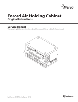
SITING
The diagrams overleaf show two typical 861 installations.
The tape card must always be sited in the left most section of the rear panel.
Note: The digital input card, the computer card and the DSP cards should not be
removed and re-sited.

Page 2
J1
J2 J21 J22
J3 J4 J5 J6 J7 J8 J9 J10 J11
J12
J13 J14
J15
J16
J17
J18 J19
J20 J23 J24
J1
J2 J21 J22
J3 J4 J5 J6 J7 J8 J9 J10 J11
J12
J13 J14
J15
J16
J17
J18 J19
J20 J23 J24
AB00 Z300
AB00 Z300
Analogue
Input
INSTALLATION PROCEDURE
Note: Observe static precautions throughout the installation period.
1. Switch off the unit and remove the power cord.
2. Remove blanking panels as required using a No. 0 pozidrive screwdriver. Retain
panel and fixings.
3. Move analogue cards to the right if required, to allow room for the new card.
4. Slide the new card into the guide rails, (see diagram above). Ensure correct card
orientation (component side of TP00 leftmost when viewed from the rear).
5. Check the card is aligned correctly and slides freely down the card guides. Do not
push the card home at this stage.
6. Loosen all analogue input card fixings.
7. Slide all analogue input cards out together, so as not to disturb the ribbon
connections between them, until approximately only a third is held in the card
guides.
8. Look at the component side of the card immediately to the left of the tape card.
Identify the red connector located, towards the top of this card and approximately
halfway down its length. It is similar in appearance to fig 3 below.
9. Similarly access the connector on the solder side of the tape card (this is the only
component on this side of the PCB).

Page 3
Pin
1
PIN 1
fig 1
fig 2
fig 3
Identify the card type to the left of the tape card. If this card is IA00 the six input
analogue card then proceed as follows:-
Connect the jumper supplied, (see figure 1 above) to the component side of IA00
with the red stripe towards the motherboard. Connect the other end of the jumper
to the connector on the solder side of the tape card, with the red stripe towards its
rear panel. Note: This will require the jumper to be twisted 180 degrees between
cards. If the ribbon is fitted reversed i.e. pin one to pin eight, the system will still
function but left and right channels will be reversed.
If the card type, to the left of the tape card, is any other analogue input card other
than IA00 then, connect the jumper supplied between the two cards with the red
stripe towards the mother board. i.e. without the 180 degree twist.
10. Loop the jumper cable downwards between the cards so as to avoid the cable
fouling on the card guides.
11. Push all the cards in gently, and together, to avoid straining the ribbon jumpers,
until the rear panels are flush to the case. If the cards are aligned correctly in the
card guides then only slight force will be required to mate the connectors.
12. Gently tighten the rear fixings using the flat blade screwdriver. Do not over
tighten.
13. Connect to the tape outputs and headphone socket as required.
14. Re-connect the power cord and switch on.
SETTING UP THE TAPE CARD
The Tape Card always follows the source currently selected with the Copy key of the
861. Each output of the 3 Outputs on the Tape Card can be independently set to one
of five possible settings.
• Fixed 2V output (Default setting for TAPE OUT and ZONE 2)
• Fixed 1.4V
• Fixed 1V
• Fixed 0.7V
• Variable (Default setting for the Headphone socket). The volume is controlled by
the Headphone Volume control, see the 861 User Guide.
The three outputs can be configured from the Meridian setup program. Open a file in
the program, then go to 861 Surround Controller, then Current Settings, then
Setup. The ‘Tape output 1’ setting corresponds to the TAPE OUT on the rear panel
and the ‘Tape output 2’ setting corresponds to the ZONE 2 output on the rear panel.
/