Page is loading ...

M212356EN-A
Quick Guide
Vaisala Indigo Compatible
Dew Point and Temperature Probes
DMP5, DMP6, DMP7, DMP8

PUBLISHED BY
Vaisala Oyj
Vanha Nurmijärventie 21, FI-01670 Vantaa, Finland
P.O. Box 26, FI-00421 Helsinki, Finland
+358 9 8949 1
Visit our Internet pages at www.vaisala.com.
© Vaisala Oyj 2019
No part of this document may be
reproduced, published or publicly
displayed in any form or by any means,
electronic or mechanical (including
photocopying), nor may its contents be
modified, translated, adapted, sold or
disclosed to a third party without prior
written permission of the copyright holder.
Translated documents and translated
portions of multilingual documents are
based on the original English versions. In
ambiguous cases, the English versions are
applicable, not the translations.
The contents of this document are subject
to change without prior notice.
Local rules and regulations may vary and
they shall take precedence over the
information contained in this document.
Vaisala makes no representations on this
document’s compliance with the local
rules and regulations applicable at any
given time, and hereby disclaims any and
all responsibilities related thereto.
This document does not create any legally
binding obligations for Vaisala towards
customers or end users. All legally binding
obligations and agreements are included
exclusively in the applicable supply
contract or the General Conditions of Sale
and General Conditions of Service of
Vaisala.
This product contains software developed
by Vaisala or third parties. Use of the
software is governed by license terms and
conditions included in the applicable
supply contract or, in the absence of
separate license terms and conditions, by
the General License Conditions of Vaisala
Group.

Table of Contents
Product Overview..............................................................................................3
Probe Structure............................................................................................................................ 3
Basic Features and Options...................................................................................................... 3
Output Parameters......................................................................................................................4
Installation...........................................................................................................5
DMP5 Probe........................................................................................................ 6
Installing with Mounting Flange 210696............................................................................... 7
DMP6 Probe........................................................................................................ 8
Installing Probe Head with Cooling Set DMP246CS.........................................................10
Cooling Set Installation Example........................................................................................... 12
DMP7 Probe.......................................................................................................13
DMP8 Probe.......................................................................................................15
Tightening the Clasp Nut..........................................................................................................17
Attaching Ball Valve Kit to Process....................................................................................... 18
Wiring................................................................................................................ 20
Attaching Probe to Indigo 200 Series Transmitter..................................21
Vaisala Insight Software.................................................................................22
Connecting to Insight Software.............................................................................................22
Modbus...............................................................................................................23
Default Communication Settings..........................................................................................23
Measurement Data Registers................................................................................................. 23
Diagnostic Data Registers.......................................................................................................24
Configuration Registers...........................................................................................................25
Test Value Registers..................................................................................................................25
Technical Support............................................................................................26
More Information.......................................................................................................................26
Warranty......................................................................................................................................26
Recycling..................................................................................................................................... 26
1

2 M212356EN-A

Product Overview
DMP series probes are dew point and temperature measurement probes with a digital output
(Modbus protocol). The probes are designed for demanding dew point measurement
applications. The probes have a two-part structure, with measurement electronics contained in
the probe body and sensor(s) in the probe head. The probe body and the probe head are
connected by a cable. Length options for this connecting cable depend on the probe model.
The probes are compatible with Vaisala Indigo transmitters. They can also be connected to
Vaisala Insight software for configuration, calibration, diagnostics, and temporary online
monitoring.
Probe Structure
1
2
3
4
5
6
7
8
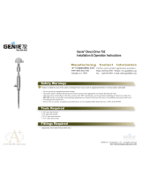
Figure 1 Probe Parts
1 Protection cap (remove before use)
2 5-pin M12 connector
3 Probe body with type label
4 Status indicator:
Green Power on and probe online,
flashes when communicating
Red Error
O Power o or indicator
disabled
5 Probe cable (do not cut)
6 Probe head (DMP7 model shown)
7 Location of sensors on the probe head.
DMP series probes have a removable
filter over the sensors that can be
replaced if it gets dirty or damaged.
8 Protection cap (remove before use)
Basic Features and Options
• Comprehensive list of output parameters. For example: relative humidity, temperature,
dew point temperature, wet-bulb temperature, absolute humidity, mixing ratio, water
vapor pressure, enthalpy. See Output Parameters (page 4).
• Sensor purge provides superior chemical resistance
• Sensor warming function minimizes condensation on sensor
• Traceable calibration certificate
• Standalone Modbus RTU over RS-485
• Compatible with Indigo series of transmitters
• Can be connected to Vaisala Insight PC software for configuration, calibration,
diagnostics, and temporary online monitoring
3

Output Parameters
Values of all available output parameters are always locked (showing the latest
valid value) when chemical purge, autocalibration, or extra heat functions are
active.
Output parameter is available
Output parameter is unavailable during sensor warming unless temperature is written to
register 0334
hex
from an external source
Output parameter is not available on this model
Table 1 Availability of Output Parameters
Output Parameter Output Unit DMP5 DMP6 DMP7 DMP8
Relative humidity %RH
Temperature °C
Dew point temperature °C
Dew/frost point temperature °C
Dew/frost point temperature at
1 atm
°C
Dew point temperature at 1 atm °C
Absolute humidity
g/m
3
Mixing ratio g/kg
Water concentration ppm
v
Water vapor pressure hPa
Water vapor saturation
pressure
hPa
Enthalpy kJ/kg
Dew point temperature
dierence
°C
Absolute humidity at NTP
g/m
3
Water mass fraction ppm
w
4 M212356EN-A

Installation
When you choose the installation location for the probe, consider the following:
• Verify the operating environment specification of the probe model. The probe head
typically has a much wider operating temperature range than the probe body.
• If the temperature of the measured environment diers greatly from ambient
temperature, the entire probe head and preferably plenty of cable must be inside the
measured environment. This prevents measurement inaccuracy caused by heat
conduction along the cable.
• Probe mounting options are model-specific.
1
2
3
4
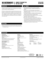
Figure 2 Example Installation
1
Mount the probe head horizontally to prevent any water condensing on the probe head
from running to the sensors.
2 Let the cable hang loosely to prevent condensed water from running along the cable to
the probe body or probe head.
3 Attach the probe body to a wall or other surface using the two mounting clips (Vaisala
item 243257SP) supplied with the probe. Each clip attaches to the installation surface with
one screw (screw hole Ø 4.2 mm).
4 Cable to Modbus master or Indigo transmitter.
The supplied mounting clips are not designed to withstand strong
vibration. Use other methods to secure the probe body if necessary. For
example, attach the probe body using a cable tie.
CAUTION!
5

DMP5 Probe
mm
[in]
136 [5.35]
Ø 25
[0.98]
M12/5
41 [1.61]
242 [9.53]
192 [7.56]
Ø 12
[0.47]
Ø 13.5
[0.53]
Ø 5
[0.2]
Probe cable
2 m [6.56 ft] or 10 m [32.8 ft]
Figure 3 DMP5 Dimensions
Vaisala DRYCAPâ Dew Point and Temperature Probe DMP5 is designed for humidity
measurement in applications with high temperatures. The long and robust steel probe and an
optional installation flange allow easy installation with adjustable depth through insulation, for
example, in ovens.
DMP5 is built for direct measurement in hot and dry processes, up to +180 °C (+356 °F). As the
probe can be directly placed in the process, there is no need for a sampling system or trace
heating. As a result, high measurement accuracy and constancy are maintained. DMP5
provides unmatched dry-end measurement accuracy at temperatures up to 140 °C; however, it
can operate safely at temperatures up to 180 °C.
• Operating temperature of probe body −40 … +80 °C (−40 … +176 °F)
• Operating temperature of probe head −40 ... +180 °C (−40 ... +356 °F)
6 M212356EN-A

Installing with Mounting Flange 210696
Mounting flange 210696 is designed for attaching Ø13.5 mm probe heads through the wall of a
process chamber or duct. The flange kit includes a flange, a sealing ring, and screws.
75 [2.95]
50 [1.97]
Drilling 16 ... 22
[0.63 ... 0.87]
105 ... 200 [4.1 ... 7.87]
1
2
3
4
5
mm
[in]
1 Wall of chamber or duct
2 Flange
3 Sealing ring
4 Self-tapping screws (B 4.2×16 DIN 7981)
5 Probe
When the temperature dierence between the process or duct and the
surroundings is large, insert the probe head as deep in the process or duct as
possible. This prevents errors caused by heat conduction along the probe cable.
7

DMP6 Probe
136 [5.35]
Ø 25
[0.98]
M12/5
357 [14.1]
334.5 [13.17]
Ø 11
[0.43]
Ø 13.5
[0.53]
Probe cable 2 m [6.56 ft]
Ø 5
[0.2]
mm
[in]
Figure 4 DMP6 Probe Dimensions
304 [11.97]
164 [6.46]112.5 [4.43]
15 [0.59]
8 [0.31]
27.5
[1.08]
40.6 [1.6]
Cooling fins
120 [4.72]
Ø 20 [0.79]
Ø 89 [3.5]
Ø 118 [4.65]
Mounting flange
Ø28 [1.1]
Ø 89 [3.5]
Screen tube
mm
[in]
Figure 5 Cooling Set DMP246CS Dimensions
8 M212356EN-A

Vaisala DRYCAPâ Dew Point Probe DMP6 is designed for humidity measurement in industrial
applications with very high temperatures. High temperature tolerance is achieved using a
passive cooling set that conducts heat away from the probe and reduces temperature to
optimal range for the sensor.
• Operating temperature of probe head 0 … +350 °C (+32 ... +662 °F)
• Operating temperature of probe body −40 … +80 °C (−40 … +176 °F)
DMP6 is built for direct measurement in temperature range 0 … +350 °C (+32 … +662 °F).
There is no need for a sampling system or trace heating. To tolerate these high temperatures
the probe head is inserted inside a cooling set that provides passive cooling. The cooling set
has removable cooling fins that allow the operating temperature profile of the probe to be
adjusted so that adequate cooling is provided for each application. The cooling system has no
moving parts, and requires no additional power or cooling utilities, so there is no risk of sensor
damage due to mechanical cooling failure.
100
-30
-20
-10
0
10
20
30
40
50
60
70
80
90
100
110
150 200 250 300 350
Temperature of measured gas (°C)
Dew point temperature (°C)
Range without cooling fins
Range with cooling fins
Figure 6 Operating Range of Probe Head
Make sure that the upper limit of the dew point measurement range is not
exceeded in low temperatures as this will lead to condensation.
You can read diagnostic measurement data from the probe using Insight software
(Diagnostics page) or Modbus protocol (diagnostic data registers) and use it to
verify your installation:
• Sensor temperature must never exceed +180 °C (+356 °F) even in exceptional
process conditions.
• Allow the probe to stabilize after installation in the cooling set, and check the
Sensor saturation ratio. If the value is below 20 %, install the cooling fins on
the cooling set (unless already installed).
9

Installing Probe Head with Cooling Set DMP246CS
• Welding equipment
• Equipment for making a hole to the process wall
• 5-mm Allen key
• 2-mm Allen key
mm
[in]
Ø 105 [4.13]
max.
50 [1.97] 125 [4.92]
8 [0.31]
2
[0.08]
Ø 89 [3.50]
Ø 118 [4.65]
1 2 3 4
Figure 7 DMP246CS Cooling Set Mounting Flange
1
Lengthening piece for thick walls (not included)
2 Welding point
3 Mounting tube
4 Mounting screws (4 pcs, M6×16 DIN 912)
10 M212356EN-A

172 [6.77]22 [0.87] 104.5 [4.11]
1 2 3 4 5
mm
[in]
Figure 8 DMP246CS Cooling Set without Mounting Flange
1 Cooling bush
2 Flange
3 Cooling bar
4 Locking screws (4 pcs, M4×6 DIN 916)
5 Mounting screws of the cooling fins (M6×60 DIN 912
1. Make a round 89.5 + 0.5 mm (3.52 + 0.02 in) hole in the process wall. Install the cooling
set horizontally whenever possible to ensure the best possible cooling performance.
2. If the process wall is more than 125 mm (4.92 in) thick, weld a lengthening piece (max. 50
mm (1.97 in)) to the mounting tube.
3. Weld the tube of the mounting flange tightly to the inner metal plate of the process wall.
4. Attach the cooling set to the mounting flange and use a 5-mm Allen key to tighten the
mounting screws. Proper tightening of the mounting screws is important for good thermal
contact.
5. If the process chamber is in use or otherwise warmer than ambient temperature, let the
cooling set warm up before inserting the probe to avoid condensation:
a. Plug the hole of the cooling bar tightly with the plug that is attached to the cooling
set.
b. If installation of the cooling fins is required, attach them at this point to let them warm
up as well. See step 9.
c. Wait for a few hours.
d. Unplug the cooling bar and continue the installation.
6. Use a 2-mm Allen key to loosen the locking screws on the cooling bar.
7. Push the probe head into the cooling bar until it meets the other end and cannot be
pushed farther. Approximately 7.5 cm (2.95 in) of the probe head will remain outside the
cooling bar.
Do not push or pull from the probe cable.CAUTION!
11

8. Tighten the locking screws to lock the probe head in place.
9. If installation of cooling fins is required, attach them around the cooling bar using a 5-mm
Allen key. Place the cooling fins so that the locking screws are not obstructed. Tighten the
two mounting screws so that the fins have good thermal contact with the cooling bar.
Cooling Set Installation Example
5
6
1 2 3
4
Figure 9 Example Installation with Cooling Set DMP246CS
1
Process chamber, maximum temperature +350 °C (+662 °F)
2 Mineral wool or other insulation, total wall thickness is < 125 mm (4.92 in) so no
lengthening piece is welded to mounting tube
3 Space outside process chamber, in ambient temperature
4 Location of dew point sensor when probe head is installed in the cooling set (under
sintered filter)
5 Tube of the mounting flange welded to inner plate of process wall
6 Cooling set attached to mounting flange using mounting screws (4 pcs)
12 M212356EN-A

DMP7 Probe
136 [5.35]
Ø 25
[0.98]
M12/5
41 [1.61]
84 [3.31]
Hex 22 [0.87]
Probe cable
2 m [6.56 ft] or 10 m [32.8 ft]
Ø 12
[0.47]
ISO 1/2”
ISO 3/8”
or NPT 1/2”
mm
[in]
Figure 10 DMP7 Dimensions
Vaisala DRYCAPâ Dew Point and Temperature Probe DMP7 is designed for low-humidity
applications. Thanks to its short probe length, it fits in installations with limited space such as
semiconductor manufacturing equipment. Other applications include industrial drying,
compressed air systems, dry rooms, and blanket gases in metal heat treatment.
• Operating temperature of probe head −40 … +80 °C (−40 … +176 °F)
• Operating temperature of probe body −40 … +80 °C (−40 … +176 °F)
• Operating pressure of probe head 0 … 10 bar (0 … 145 psia)
13

See installation instructions provided with the Swagelok installation kit.
mm
[in]
21 3 4 5 6
42 [1.65]
84 [3.31]
Figure 11 DMP7 Installation to Pipeline Using a Swagelok Installation Kit
1 Max. process pressure 10 bar (145 psi), max temperature +80 °C (+176 °F)
2 Probe head
3 Duct connector
4 ISO1/2", ISO3/8" or NPT1/2" thread
5 Swagelok connector
6 Ferrules
When installed in a process with a pressure diering from normal atmospheric
pressure, input the correct pressure into the pressure compensation setpoint
register of the probe. This allows the probe to apply the appropriate pressure
compensation into its measurement results.
More Information
‣
Configuration Registers (page 25)
14 M212356EN-A

DMP8 Probe
136 [5.35]
Probe cable 2 m [6.56 ft]
Ø 25
[0.98]
M12/5
Ø 12
[0.47]
41 [1.61]
Ø 13.5
[0.53]
Fitting body
ISO1/2” or NPT1/2”
Ø 5
[0.2]
mm
[in]
268 [10.55]
230 [9.06]
41 ... 185 [1.16 ... 7.28]
Figure 12 DMP8 Dimensions
Vaisala DRYCAPâ Dew Point and Temperature Probe DMP8 is designed for industrial low-
humidity applications such as industrial drying, compressed air systems, and semiconductor
industry. It can be installed in a 1/2" NPT or ISO thread with adjustable insertion depth.
An optional ball-valve installation kit allows for inserting or detaching the probe from a
pressurized line.
• Operating temperature of probe head −40 … +80 °C (−40 … +176 °F)
• Operating temperature of probe body −40 … +80 °C (−40 … +176 °F)
• Operating pressure of probe head 0 … 4 MPa (0 … 40 bar)
15

1
2
3
Figure 13 DMP8 Probe Head
1 Clasp nut, 24 mm hex nut
2 Fitting body, 27 mm hex head
3 Leak screw (on ISO 1/2" fitting body
HM47432 only)
Fitting body with a leak screw can be useful when the probe head cannot be
installed directly in the pressurized process or process pipe. The leak screw allows
a small sample flow to escape from the process out to atmospheric pressure,
enabling a fast response time although the probe is not installed in the process.
1
2
Figure 14 Sealing of Fitting Body into
Process
1 Fitting body with 24 mm hex nut and
tapered thread
2 Seal with a suitable thread sealant. For
example, LOCTITEâ No. 542 with
activator No. 7649, MEGA-PIPE EXTRA
No. 7188, or PTFE tape.
Follow the instructions of the sealant manufacturer.
PTFE tape does not lock the parts together. Use two fork wrenches (24 mm and
27 mm) when tightening and opening the clasp nut of the probe.
16 M212356EN-A

Tightening the Clasp Nut
1. Adjust the probe to a suitable depth according to the type of installation.
2. Tighten the clasp nut to finger tightness.
3. Draw a line on the fitting screw and the clasp nut to mark their position.
4. Tighten the nut a further 50 … 60º (1/6 turn) with a wrench. If you have a suitable torque
wrench, tighten the nut to max 45 ±5 Nm (33 ±4 ft-lbs).
Do not overtighten the clasp nut.
Take care not to damage the probe body. A damaged body makes
the probe less tight and may prevent it from going through the clasp nut.
CAUTION!
In pressurized processes it is essential to tighten the supporting
nuts and screws very carefully to prevent loosening of the probe by the action of
pressure.
CAUTION!
When installed in a process with a pressure diering from normal atmospheric
pressure, input the correct pressure into the pressure compensation setpoint
register of the probe. This allows the probe to apply the appropriate pressure
compensation into its measurement results.
More Information
‣
Configuration Registers (page 25)
17

Attaching Ball Valve Kit to Process
G1/2
ISO 228/1
Ø21.5 (drilling)
Ø14
Ø14
Ø14
2
3
4
5
1
1 Ball valve handle: must point to the same direction as the ball valve body when installing.
2 Extension nipple, threads G1/2 ISO228/1 and R1/2 ISO7/1.
3 Ball valve body. When tightening the assembly, turn only from the ball valve body.
4 Ball of the ball valve.
5 Welding joint, threads R1/2 ISO7/1.
1. Attach the welding joint to the process pipe or chamber.
2. Apply a sealant (MEGA-PIPE EXTRA No. 7188 or LOCTITEâ No. 542 with activator No.
7649) on the threads of the welding joint and screw the bottom of the ball valve onto the
welding joint.
18 M212356EN-A
/