Page is loading ...

UM11058
TEA1936xDB1463 45 W USB-PD and Quick Charge demo
board
Rev. 1 — 5 February 2018 User manual
Document information
Information Content
Keywords TEA1936xDB1463, TEA1936x universal serial bus, power delivery, USB-PD,
quick charge USB-PD 2.0 and 3.0, type-C
Abstract This user manual describes the performance, technical data, and the
connections of the TEA1936xDB1463 demo board. The TEA1936xDB1463
demo board operates at mains voltages from 90 V (AC) up to 264 V (AC) with
an output voltage from 5 V (DC) up to 20 V (DC).

NXP Semiconductors
UM11058
TEA1936xDB1463 45 W USB-PD and Quick Charge demo board
UM11058 All information provided in this document is subject to legal disclaimers. © NXP B.V. 2018. All rights reserved.
User manual Rev. 1 — 5 February 2018
2 / 22
Revision history
Rev Date Description
v.1 20180205 first issue

NXP Semiconductors
UM11058
TEA1936xDB1463 45 W USB-PD and Quick Charge demo board
UM11058 All information provided in this document is subject to legal disclaimers. © NXP B.V. 2018. All rights reserved.
User manual Rev. 1 — 5 February 2018
3 / 22
1 Introduction
Warning
The non-insulated high voltages that are present when operating this product,
constitute a risk of electric shock, personal injury, death and/or ignition of fire.
This product is intended for evaluation purposes only. It shall be operated in a
designated test area by personnel qualified according to local requirements and
labor laws to work with non-insulated mains voltages and high-voltage circuits. This
product shall never be operated unattended.
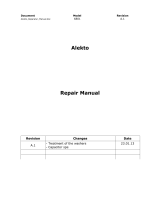
This user manual describes the operation of the TEA1936xDB1463 demo board. The
TEA1936xDB1463 features the quasi-resonant controller TEA19361, the synchronous
rectifier controller TEA1993, and the USB-PD Type-C and QC2.0/3.0 controller
TEA19051B.
The TEA1936xDB1463 demo board is designed for delivering a maximum output power
of 45 W at a maximum current of 3 A. Output voltages can be chosen from 5 V up to
20 V.
The TEA1936xDB1463 provides an effective solution with a low current ripple and high
efficiency for USB-PD and quick charge applications.
aaa-027401
TEA19361
QR CONTROLLER
SR CONTROLLER
TEA1993
OPTO/COMMS
USB-PD TYPE-C
AND
QUICK CHARGE
CONTROLLER FOR SMPS
VBus
USB
TYPE-C
PLUG
DP
DM
CC1
CC2
GND
TEA19051B
+-
Figure 1. TEA1936xDB1463 principle schematic

NXP Semiconductors
UM11058
TEA1936xDB1463 45 W USB-PD and Quick Charge demo board
UM11058 All information provided in this document is subject to legal disclaimers. © NXP B.V. 2018. All rights reserved.
User manual Rev. 1 — 5 February 2018
4 / 22
1.1 Key features
• Multi-protocol support for USB-PD 2.0 and 3.0, Quick Charge 2.0 and 3.0
• Functionality user-configurable end of line
• Best-in-class energy efficiency meeting all DOE & EU CoC requirements
• < 30 mW no-load power, low audible noise, low output voltage ripple
• Small size due to high near-full digital integration level and > 15.9 W/CI power density
• Best-in-class Thermal management
• Safe solution with extensive set of hardware-integrated protection features
• Complete one-stop-shop solution from NXP Semiconductors minimizing development
time and research and development cost
1.2 Applications
Mobile chargers with Type-C connector for:
• Mobile phones
• Smart phones
• Tablets
• Notebooks
The new smart charger platform of NXP Semiconductors helps designers of travel
adapters to maximize power output for the smallest form-factor with a short bill of
materials.
The result is a cost-effective design. It meets the requirements published by Energy Star,
the Department of Energy (DoE) in the United States, the Ecodesign Directive of the
European Union, the European Code of Conduct, and other guidelines.
Supporting hardware (UTC) and software (GUI) for USB-PD available for jump-starting
application.

NXP Semiconductors
UM11058
TEA1936xDB1463 45 W USB-PD and Quick Charge demo board
UM11058 All information provided in this document is subject to legal disclaimers. © NXP B.V. 2018. All rights reserved.
User manual Rev. 1 — 5 February 2018
5 / 22
2 Safety warning
The TEA1936xDB1463 demo board is connected to the mains voltage. Avoid touching
the board while it is connected to the mains voltage and when it is in operation. An
isolated housing is obligatory when used in uncontrolled, non-laboratory environments.
Galvanic isolation from the mains phase using a fixed or variable transformer is always
recommended.
Figure 2 shows the symbols on how to recognize these devices.
019aab173
019aab174
a. Isolated b. Not isolated
Figure 2. Isolation symbols
3 Specifications
Table 1. TEA1936xDB1486 specifications
Symbol Parameter Value
V
mains
AC mains voltage 90 V (AC) up to 264 V (AC)
P
out(max)
maximum output power 45 W
f
mains
mains frequency 47 Hz to 63 Hz
P
idle
no-load input power < 30 mW
η efficiency > 92 %; at P
out(max)
V
out
output voltage 5 V (DC) to 20 V (DC)
I
out(max)
maximum output current 3 A
V
ripple(burst)
output voltage ripple in burst mode 100 mV (p-p); at cable end
V
ripple(full)
output voltage ripple at continuous
switching
80 mV (p-p); at cable end
EMI conducted EMI −7 dB
CMN common-mode noise < 2 V (p-p)
±15 kV; through airESD electrostatic discharge
±8 kV; via contact

NXP Semiconductors
UM11058
TEA1936xDB1463 45 W USB-PD and Quick Charge demo board
UM11058 All information provided in this document is subject to legal disclaimers. © NXP B.V. 2018. All rights reserved.
User manual Rev. 1 — 5 February 2018
6 / 22
4 Board photographs
Figure 3. TEA1936xDB1463 demo board
a. Top view b. Bottom view
Figure 4. TEA1936xDB1463

NXP Semiconductors
UM11058
TEA1936xDB1463 45 W USB-PD and Quick Charge demo board
UM11058 All information provided in this document is subject to legal disclaimers. © NXP B.V. 2018. All rights reserved.
User manual Rev. 1 — 5 February 2018
7 / 22
5 TEA1936xDB1463 demo board connections
The TEA1936xDB1463 demo board is a universal mains supplied application. The output
is the Type-C receptacle. Setting the output voltage is done through the USB type-C
interface. Additionally, the TEO II graphical user interface software provides the option
to program other output voltages and limit currents into the TEA19051B PD controller IC.
Section 7 lists the default settings.
Figure 5. TEA1936xDB1463 demo board connections

NXP Semiconductors
UM11058
TEA1936xDB1463 45 W USB-PD and Quick Charge demo board
UM11058 All information provided in this document is subject to legal disclaimers. © NXP B.V. 2018. All rights reserved.
User manual Rev. 1 — 5 February 2018
8 / 22
6 TEA1936xDB1463 demo board performance
6.1 Efficiency
Table 2. Efficiency at 5 V output (PCB end)
Load Efficiency at
115 V (AC)(%)
Efficiency at
230 V (AC)(%)
10 % (0.3 A) 87.8 84.4
25 % (0.75 A) 88.6 85.7
50 % (1.5 A) 89.3 86.6
75 % (2.25 A) 90 86.9
100 % (3 A) 90.1 88.9
4-point average 89.5 87
Table 3. Efficiency at 9 V output (PCB end)
Load Efficiency at
115 V (AC)(%)
Efficiency at
230 V (AC)(%)
10 % (0.3 A) 88.5 86.1
25 % (0.75 A) 90.0 87.6
50 % (1.5 A) 91.2 89.0
75 % (2.25 A) 92.5 90.7
100 % (3 A) 92.4 92.1
4-point average 91.5 89.8
Table 4. Efficiency at 15 V output (PCB end)
Load Efficiency at
115 V (AC)(%)
Efficiency at
230 V (AC)(%)
10 % (0.3 A) 86.5 84.8
25 % (0.75 A) 88.8 87.7
50 % (1.5 A) 91.8 90.5
75 % (2.25 A) 93.2 92.0
100 % (3 A) 92.9 93.0
4-point average 91.7 90.8

NXP Semiconductors
UM11058
TEA1936xDB1463 45 W USB-PD and Quick Charge demo board
UM11058 All information provided in this document is subject to legal disclaimers. © NXP B.V. 2018. All rights reserved.
User manual Rev. 1 — 5 February 2018
9 / 22
Table 5. Efficiency at 20 V output (PCB end)
Load Efficiency at
115 V (AC)(%)
Efficiency at
230 V (AC)(%)
10 % (0.23 A) 86.1 84.2
25 % (0.575 A) 88.9 87.5
50 % (1.15 A) 91.8 89.9
75 % (1.725 A) 92.8 92.3
100 % (2.3 A) 93.0 92.8
4-point average 91.6 90.6
6.2 No-load power consumption at 5 V output
Table 6. No-load power consumption
Type-C cable disconnected.
Input voltage (V (AC)) Input frequency (Hz) No-load power (mW)
90 60 21.1
115 60 21.6
150 60 22.2
180 50 22.3
200 50 22.9
230 50 23.9
264 50 28.4

NXP Semiconductors
UM11058
TEA1936xDB1463 45 W USB-PD and Quick Charge demo board
UM11058 All information provided in this document is subject to legal disclaimers. © NXP B.V. 2018. All rights reserved.
User manual Rev. 1 — 5 February 2018
10 / 22
6.3 ElectroMagnetic Interference (EMI)
Protective earth is connected to secondary ground.
Figure 6. Conducted EMI at full load 115 V (AC)/60 Hz
Protective earth is connected to secondary ground.
Figure 7. Conducted EMI at full load 230 V (AC)/50 Hz; pass with > 5 dB margin

NXP Semiconductors
UM11058
TEA1936xDB1463 45 W USB-PD and Quick Charge demo board
UM11058 All information provided in this document is subject to legal disclaimers. © NXP B.V. 2018. All rights reserved.
User manual Rev. 1 — 5 February 2018
11 / 22
6.4 Thermal
a. Top side b. Bottom side
Figure 8. Thermal performance; V
in
= 115 V (AC); P
out
= 45 W
a. Top side b. Bottom side
Figure 9. Thermal performance; V
in
= 230 V (AC); P
out
= 45 W
Note: Typical temperature distribution at T
amb
= 25 °C; PCB in free air, natural
convection, and radiation only. For the TEA1936xDB1463 demo board, the voltage levels
must not exceed 20 V also. Current limit levels must not exceed 3 A. Power limit levels
must not exceed 45 W.

NXP Semiconductors
UM11058
TEA1936xDB1463 45 W USB-PD and Quick Charge demo board
UM11058 All information provided in this document is subject to legal disclaimers. © NXP B.V. 2018. All rights reserved.
User manual Rev. 1 — 5 February 2018
12 / 22
7 PDO settings
Table 7 shows the settings of the output voltages and currents for the efficiency
measurement.
Table 7. PDO settings
Default values for demo board TEA1936xDB1463
PDO (#) V
out
(V) I
out
(A)
1 5 3
2 9 3
3 15 3
4 20 2.3
PDO settings can be changed by reprogramming the MTP settings of the TEA19051B
via UTC using the TEO-II software (see the TEA190x Evaluation Overdrive (TEO) user
manual (Ref. 1).
Note: The PDOs must have an ascending voltage and power in order to work correctly.
So, V(PDO, i + 1) > V(PDO, i) and also P(PDO, i + 1) > P(PDO, i). Also, for the
TEA1936xDB1463 demo board, the voltage levels must not exceed 20 V. Current limit
levels must not exceed 3 A. Power limit levels must not exceed 45 W.

NXP Semiconductors
UM11058
TEA1936xDB1463 45 W USB-PD and Quick Charge demo board
UM11058 All information provided in this document is subject to legal disclaimers. © NXP B.V. 2018. All rights reserved.
User manual Rev. 1 — 5 February 2018
13 / 22
8 Schematic
The schematic of the TEA1936xDB1463 comprises the TEA19361 quasi-resonant controller, the TEA1993 synchronous rectifier controller, and the TEA19051B
USB-PD/QC controller.
aaa-027411
F1
L
N
L1
2 x 1.2 mH
D21
AS3PM
D24
AS3PM
D23
AS3PM
D22
AS3PM
R16
Q1
IPD80R280P7
100 Ω
D5
BAS316
L3
120 µH
1
2
4
3
CX1
47 nF
310 V (AC)
SG1
sparkgap
6 mm
R24
84.5 kΩ
R15
2.2 kΩ
RT2
100 kΩ
C17
1 nF
50 V
C14
1 nF
50 V
R22
5.6 kΩ
USB
TCLT1008
R17
4.7 Ω
D15
BAS321
C3
10 µF
100 V
C15
470 nF
50 V
C36
10 µF
35 V
C19
22 pF
50 V
R18
0.43 Ω
R19
0.43 Ω
D4
S1ML
U10
AUX
CTRL
n.c.
PROTECT
C29
22 µF
400 V
C33
22 µF
400 V
R7
100 kΩ
R13
0 Ω
D3
S2M
C12
2.2 nF
630 V
C1
22 µF
400 V
R64
84.5 kΩ
GND_USB
R25
120 kΩ
HV
DRIVER
4
3
ISENSE
GND
VCCL
VCCH
6
7
9
8
10
5
4
2
3
1
TEA19361
R21
1 kΩ
C41
10 µF
25 V
GATE
VCC
U1
OPTOOPTOC
SGND
NTC/GPIO1
ISNS
NTC/GPIO2PROT
VCONN2/SCL
VSNS
16
15
14
13
12
11
9
17
10
1
2
3
4
5
6
8
7
SW
TEA19051B
GND
DISCH
SW
DISCH
CC1
CC2
DP
VCONN1/SDA
EP
DM
CC1
GND_USB
CC2
DP
SDA
SCL
DM
SOURCE
DRAIN
S
R
D
R
A
I
N
4
5
6
15
VBUS
DRAIN
16
8
5
1413
1
3
12
11
10
XV
GND
CAP
TEA1993
U2
3
2
1
R5
C20
470 pF
100 V
CY1
220 pF
250 V (AC)
10 Ω
GND_USB
R31
R62
47 Ω
C4
560 µF
25 V
C30
560 µF
25 V
C10
1 µF
25 V
C6
4.7 µF
25 V
Q3
P3MN2R4-30MLD
T1
RM8, 360 µH
Q2
BSC060N10NS3
FB3
K5B RH 3.5 x 4.5 x 0.8 - T52
FB2
BLM21PG220SH1
R39
1 MΩ
0.011 Ω
R73
47 kΩ
R57
0 kΩ
R54
24.3 kΩ
R26
47 kΩ
R8
5.1 kΩ
C5
100 nF
50 V
R9
1 kΩ
C38
10 nF
50 V
R53
178 kΩ
R55
150 Ω
D26
BAS521
U3A
TCLT1008
R11
330 Ω
R50
1
2
120 Ω
C7
4.7 µF, 25 V
R60
3.3 kΩ
VO_USB
Vo
Vo
GND_USB
R14
10 Ω
R52
10 Ω
R61
10 Ω
R51
10 Ω
2 AT / 250 V (AC)
A1
A2
A3
A4
A5
A6
A7
A8
A9
A10
A11
A12
B12
B11
B10
B9
B8
B7
B6
B5
B4
B3
B2
B1
GND1
TX1+
TX1-
VBUS1
CC1
D1+
D1-
SBU1
VBUS2
RX2-
RX2+
GND2
GND4
RX1+
RX1-
VBUS4
SBU2
D2-
D2+
CC2
VBUS3
TX2-
TX2+
GND3
CGND
SH1
G4G3G2G1
SH2 SH3 SH4
1
2
3
4
SDA
CC2
CC1
SDA
Vo
SCL
DP
DM
VO_USB
GND_USB
CN1
12401548E4#2AD2
PESD24VS2UT
D17
PESD5V2S2UT
D1
PTVS24VS1UR
D25
PESD5V2S2UT
R69
10 Ω
10 Ω
R71, 0 Ω
R70
GND
Vo
SCL
Figure 10. TEA1936xDB1463 schematic diagram

NXP Semiconductors
UM11058
TEA1936xDB1463 45 W USB-PD and Quick Charge demo board
UM11058 All information provided in this document is subject to legal disclaimers. © NXP B.V. 2018. All rights reserved.
User manual Rev. 1 — 5 February 2018
14 / 22
aaa-027412
SDA
SDA_IN
V
in IN
5
4
OUT
MIC5233-3V3
ADJ
8
VCC
WP
SCL
SDA
SDA
SDA_OUT
3.3 V
SCL_OUT
+3V3
GND
SCL
SDA
+3V3
GND
SCL
1
2
3
4
1
2
3
4
A0
A1
A2
VSS
7 6
1 2 3 4
5
GND
EN
1
2
3
R6
C1
100 nF
35 V
C2
2.2 µF
6.3 V
R8
0 Ω
U2
24FC256
CN2 n.m.
22-28-4040
CN3 n.m.
SMS-104-01-G-S
CN1
TMS-104-01-G-S-RA
R1
10 kΩ
n.m.
R2
3.3 kΩ
R3
3.3 kΩ
0 Ω
R4
10 Ω
R5
10 Ω
R7
0 Ω
SDL_IN
SDA
SCL
WP
Vin
GND
SCL
1
2
3
4
U1
n.m. = not mounted
Figure 11. Optional EEPROM demo board EEPROM_DB1418 with I
2
C connections

NXP Semiconductors
UM11058
TEA1936xDB1463 45 W USB-PD and Quick Charge demo board
UM11058 All information provided in this document is subject to legal disclaimers. © NXP B.V. 2018. All rights reserved.
User manual Rev. 1 — 5 February 2018
15 / 22
9 Bill Of Materials (BOM)
Table 8. TEA1936xDB1463 bill of materials
Reference Description and values Part Number Manufacturer
C1 capacitor; 22 μF; 20 %; 400 V; ALU; D13xL17mm EKM226M2GJ17RR SAMXON
C3 capacitor; 10 µF; 20 %; 100 V; ALU; THT 100YXJ10M5X11 Rubycon
C4 capacitor; 560 μF; 20 %; 25 V; ALU; THT A750MS567M1EAAE015 KEMET
C5 capacitor; 100 nF; 10 %; 50 V; X7R; 0402 C1005X7R1H104K050BB TDK
C6 capacitor; 4.7 μF; 10 %; 25 V; X5R; 0603 C1608X5R1E475K080AC TDK
C7 capacitor; 4.7 μF; 10 %; 16 V; X5R; 0603 C1608X5R1C475K080AC TDK
C10 capacitor; 1 μF; 10 %; 25 V; X7R; 0603 - -
C12 capacitor; 2200 pF; 10 %; 630 V; X7R; 1206 C1206C222KBRAC KEMET
C14 capacitor; 1 nF; 10 %; 50 V; X7R; 0603 - -
C15 capacitor; 470 nF; 10 %; 50 V; X7R; 0603 C1608X7R1H474K TDK
C17 capacitor; 1 nF; 10 %; 50 V; X7R; 0603 - -
C19 capacitor; 22 pF; 5 %; 50 V; C0G; 0603 - -
C20 capacitor; 470 pF; 10 %; 100 V; X7R; 0603 - -
C29 capacitor; 22 μF; 20 %; 400 V; ALU; D13xL17mm EKM226M2GJ17RR SAMXON
C30 capacitor; 560 μF; 20 %; 25 V; ALU; THT A750MS567M1EAAE015 KEMET
C33 capacitor; 22 μF; 20 %; 400 V; ALU; D13xL17mm EKM226M2GJ17RR SAMXON
C36 capacitor; 10 µF; 20 %; 35 V; ALU; THT UVR1V100MDD6TP Nichicon
C38 capacitor; 10 nF; 10 %; 50 V; X7R; 0402 - -
C41 capacitor; 10 μF; 10 %; 25 V; X5R; 0603 C1608X5R1E106M080 TDK
CN1 Connector; USB 3.1 Type-C receptacle R/A 12401548E4#2A Amphenol
CY1 capacitor; 220 pF; 10 %; 250 V (AC); B; THT; X1/
Y2
DE2B3KY221KA2BM01F Murata
D1 diode; TVS; unidirectional; 24 V; 400 W PTVS24VS1UR NeXPeria USA Inc
D2 diode; ESD protection; 24 V; 3 A PESD24VS2UT NeXPeria USA Inc
D3 diode; 1 kV; 2 A S2M Fairchild
D4 diode; 1 kV; 1 A S1ML Taiwan Semiconductor
D5 diode; 100 V; 250 mA BAS316 NeXPeria USA Inc
D15 diode; 200 V; 250 mA BAS321 NeXPeria USA Inc
D17; D25 diode; ESD protection; 30 kV; 3 A PESD5V2S2UT NXP Semiconductors
D21; D22;
D23; D24
diode; 1 kV; 3 A AS3PM-M3/86A Vishay
D26 diode; 300 V; 250 mA BAS521 NeXPeria USA Inc
F1 fuse; slow blow; 250 V; 2 A MCPMP2A250V Multicomp
FB2 ferrite bead; 0.009 Ω; 6 A; 0805 BLM21PG220SH1D Murata
FB3 ferrite bead; K5B RH 3.5 × 4.5 × 0.8 K5B RH 3.5 x 4.5 x 0.8 - T52 King Core Electronics
Inc.

NXP Semiconductors
UM11058
TEA1936xDB1463 45 W USB-PD and Quick Charge demo board
UM11058 All information provided in this document is subject to legal disclaimers. © NXP B.V. 2018. All rights reserved.
User manual Rev. 1 — 5 February 2018
16 / 22
Reference Description and values Part Number Manufacturer
L1 inductor CM; 2 ×1.2 mH; Cu = 0.27 mm; 18T:18T T8x4x4 H5C3 TDK
L3 inductor; 120 μH; 850 mA; 0.22 Ω 744772121 Würth Elektronik
Q1 MOSFET-N; 800 V; 0.28 Ω; 17 A IPD80R280P7ATMA1 Infineon
Q2 MOSFET-N; 100 V; 90 A; 0.006 Ω; TDSON BSC060N10NS3GATMA1 Infineon
Q3 MOSFET-N; 30 V; 2.4 mΩ; 70 A PSMN2R4-30MLD NeXPeria USA Inc
R5 resistor; 10 Ω; 1 %; 63 mW; 0603 - -
R7 resistor; 100 kΩ; 1 %; 660 mW; 1206 ERJP08F1003V Panasonic
R8 resistor; 5.1 kΩ; 1 %; 63 mW; 0402 - -
R9 resistor; 1 kΩ; 1 %; 63 mW; 0402 - -
R11 resistor; 330 Ω; 1 %; 63 mW; 0402 - -
R13 resistor; jumper; 0 Ω; 250 mW; 1206 - -
R14; R51;
R52; R61
resistor; 22 Ω; 1 %; 100 mW; 0402 ERJ2RKF22R0X Panasonic
R15 resistor; 2.2 kΩ; 1 %; 63 mW; 0603 - -
R16 resistor; 100 Ω; 1 %; 100 mW; 0603 - -
R17 resistor; 4.7 Ω; 1 %; 100 mW; 0603 - -
R18; R19 resistor; 0.43 Ω; 1 %; 250 mW; 0805 ERJS6QFR43V Panasonic
R21 resistor; 1 kΩ; 1 %; 63 mW; 0603 - -
R22 resistor; 5.6 kΩ; 1 %; 63 mW; 0603 - -
R24 resistor; 84.5 kΩ; 1 %; 660 mW; 500 V; 1206 ERJP08F8452V Panasonic
R25 resistor; 120 kΩ; 1 %; 250 mW; 250 V; 0603 ERJPA3F1203V Panasonic
R26 resistor; NTC; 47 kΩ; 5 %; 180 mW; 3980 K B57321V2473J060 EPCOS
R31 resistor; 0.011 Ω; 1 %; 1 W; 1206 ERJ8CWFR011V Panasonic
R39 resistor; 1 MΩ; 1 %; 63 mW; 0402 CRCW04021M00FKED Vishay
R50 resistor; 120 Ω; 1 %; 100 mW; 0402 ERJ2RKF1200X Panasonic
R53 resistor; 178 kΩ; 1 %; 63 mW; 0402 - -
R54 resistor; 24.3 kΩ; 1 %; 63 mW; 0402 - -
R55 resistor; 150 Ω; 1 %; 100 mW; 0402 ERJ2RKF1500X Panasonic
R57 resistor; 0 Ω; 1 %; 63 mW; 0402 - -
R60 resistor; 3.3 kΩ; 1 %; 63 mW; 0402 - -
R62 resistor; 100 Ω; 1 %; 500 mW; 0805 ERJP6WF1000V Panasonic
R64 resistor; 84.5 kΩ; 1 %; 660 mW; 500 V; 1206 ERJP08F8452V Panasonic
R69; R70 resistor; 10 Ω; 1 %; 100 mW; 0402 ERJ2RKF10R0X Panasonic
R71 resistor; jumper; 0 Ω; 100 mW; 0402 ERJP6WF47R0V Panasonic
R73 resistor; NTC; 47 kΩ; 5 %; 180 mW; 2980 K B57321V2473J060 EPCOS
RT2 resistor; NTC; 100 kΩ; 5 %; 100 mW; 4190 K NTCLE100E3104JB0 Vishay
T1 Transformer; RM8; 360 µH RM8 (TR1083) NXP Semiconductors

NXP Semiconductors
UM11058
TEA1936xDB1463 45 W USB-PD and Quick Charge demo board
UM11058 All information provided in this document is subject to legal disclaimers. © NXP B.V. 2018. All rights reserved.
User manual Rev. 1 — 5 February 2018
17 / 22
Reference Description and values Part Number Manufacturer
U1 TEA19051B; HVSON16 TEA19051B (HVSON16) NXP Semiconductors
U2 synchronous rectification controller; TEA1993 TEA1993 NXP Semiconductors
U10 SMTP controller; TEA19361 TEA19361 NXP Semiconductors
U3 optocoupler; NPN; 70 V; 50 mA TCLT1008 Vishay
Table 9. EEPROM_DB1418 bill of materials
Reference Description and values Part Number Manufacturer
C1 capacitor; 100 nF; 10 %; 35 V; X7R; 0402 - -
C2 capacitor; 2.2 μF; 20 %; 6.3 V; X5R; 0402 GRM155R60J225ME15D Murata
CN1 header; right angle; 1 × 4-way; 1.27 mm TMS-104-01-G-S-RA SAMTEC
CN2 header; not mounted; straight; 1 × 4-way;
2.54 mm
22-28-4040 Molex
CN3 receptacle; not mounted; straight; 1 × 4-way;
1.27 mm
SMS-104-01-G-S SAMTEC
R1 resistor; not mounted; 10 kΩ; 1 %; 63 mW; 0402 CRCW040210K0FKED Vishay
R2 resistor; 3.3 kΩ; 1 %; 63 mW; 0402 CRCW04023K30FKED Vishay
R3 resistor; 3.3 kΩ; 1 %; 63 mW; 0402 CRCW04023K30FKED Vishay
R4 resistor; 10 Ω; 1 %; 200 mW; 0402 ERJ-PA2F10R0X Panasonic
R5 resistor; 10 Ω; 1 %; 200 mW; 0402 ERJ-PA2F10R0X Panasonic
R6; R7; R8 resistor; jumper; 0 Ω; 63 mW; 0402 CRCW04020000Z0ED Vishay
U1 LDO; 3.3 V MIC5233-3.3YM5 TR MICREL
U2 EEPROM; 256 kb; I
2
C; CMOS 24FC256-I/SN Microchip

NXP Semiconductors
UM11058
TEA1936xDB1463 45 W USB-PD and Quick Charge demo board
UM11058 All information provided in this document is subject to legal disclaimers. © NXP B.V. 2018. All rights reserved.
User manual Rev. 1 — 5 February 2018
18 / 22
10 Layout
a. Top view layout and assembly
b. Bottom view layout and assembly
Figure 12. TEA1936xDB1463 demo board layout

NXP Semiconductors
UM11058
TEA1936xDB1463 45 W USB-PD and Quick Charge demo board
UM11058 All information provided in this document is subject to legal disclaimers. © NXP B.V. 2018. All rights reserved.
User manual Rev. 1 — 5 February 2018
19 / 22
a. Top view and assembly b. Bottom view and assembly
Figure 13. EEPROM_DB1418 demo board layout

NXP Semiconductors
UM11058
TEA1936xDB1463 45 W USB-PD and Quick Charge demo board
UM11058 All information provided in this document is subject to legal disclaimers. © NXP B.V. 2018. All rights reserved.
User manual Rev. 1 — 5 February 2018
20 / 22
11 Abbreviations
Table 10. Abbreviations
Acronym Description
USB Universal Serial Bus
PD Power Delivery
QC Quick Charge
UTC Universal Type-C Controller
PDO Power Data Object
MTP Multiple Times Programmable
TEO TEA190x Evaluation Overdrive
12 References
1 UM11014 user manual TEA190x Evaluation Overdrive (TEO); 2017, NXP
Semiconductors
/