Page is loading ...

Copyright © December, 2011. Revised April, 2015. For Machines Mfg. Since 8/11
MODEL SB1001
8K
™
8" X 18"
VARIABLE SPEED LATHE
OWNER'S MANUAL

Customer Service
We stand behind our machines. If you have any service questions, parts requests or general questions
about your purchase, feel free to contact us.
South Bend Lathe Co.
P.O. Box 2027
Bellingham, WA 98227
Phone: (360) 734-1540
Fax: (360) 676-1075 (International)
Fax: (360) 734-1639 (USA Only)
Email: [email protected]
Updates
For your convenience, any updates to this manual will be available to download free of charge
through our website at:
www.southbendlathe.com
Scope of Manual
This manual helps the reader understand the machine, how to prepare it for operation, how to control
it during operation, and how to keep it in good working condition. We assume the reader has a basic
understanding of how to operate this type of machine, but that the reader is not familiar with the
controls and adjustments of this specific model. As with all machinery of this nature, learning the
nuances of operation is a process that happens through training and experience. If you are not an
experienced operator of this type of machinery, read through this entire manual, then learn more
from an experienced operator, schooling, or research before attempting operations. Following this
advice will help you avoid serious personal injury and get the best results from your work.
Manual Feedback
We've made every effort to be accurate when documenting this machine. However, errors sometimes
happen or the machine design changes after the documentation process—so
the manual may not
exactly match your machine.
If a difference between the manual and machine leaves you in doubt,
contact our
customer service for clarification.
We highly value customer feedback on our manuals. If you have a moment, please share your
experience using this manual. What did you like about it? Is there anything you would change to
make it better? Did it meet your expectations for clarity, professionalism, and ease-of-use?
South Bend Lathe, Inc.
C
/O Technical Documentation Manager

Table of Contents
INTRODUCTION ............................................................... 3
About This Machine .............................................3
Foreword ............................................................. 3
8K
™
Lathe ...........................................................3
Identification ........................................................ 4
Basic Controls & Components.............................5
Master Power Switch ........................................... 5
Control Panel ......................................................5
Carriage .............................................................. 6
Tailstock .............................................................6
Product Specifications .........................................7
SAFETY ................................................................................9
Understanding Risks of Machinery ....................9
Basic Machine Safety ..........................................9
Additional Metal Lathe Safety ..........................11
Additional Chuck Safety....................................12
PREPARATION .............................................................. 13
Preparation Overview ........................................13
Required for Setup .............................................13
Power Supply Requirements ............................. 14
Availability ........................................................14
Full-Load Current Rating ..................................14
Circuit Requirements .........................................14
Grounding Requirements ...................................15
Extension Cords ................................................15
Unpacking ..........................................................16
Inventory ............................................................16
Cleaning & Protecting .......................................17
Location ..............................................................18
Physical Environment ........................................18
Electrical Installation ........................................18
Lighting ............................................................18
Weight Load ...................................................... 18
Space Allocation ................................................18
Leveling & Mounting .........................................19
Leveling ............................................................19
Mounting...........................................................19
Lubricating Lathe .............................................. 20
Power Connection ..............................................20
Connecting Power ..............................................20
Disconnecting Power ..........................................20
Test Run .............................................................21
Spindle Break-In ................................................23
Recommended Adjustments .............................. 23
OPERATION .................................................................... 24
Operation Overview ...........................................24
Chuck & Faceplate Mounting ...........................25
Chuck Installation .............................................25
Chuck Removal ..................................................27
Scroll Chuck Clamping ......................................27
4-Jaw Chuck .......................................................28
Mounting Workpiece ..........................................28
Faceplate ............................................................29
Tailstock .............................................................30
Positioning Tailstock .........................................30
Using Quill ........................................................30
Installing Tooling ..............................................30
Offsetting Tailstock ...........................................31
Aligning Tailstock to Spindle Centerline ............31
Centers ...............................................................33
Dead Centers .....................................................33
Live Centers ...................................................... 33
Mounting Center in Spindle ............................... 34
Removing Center from Spindle ...........................34
Mounting Center in Tailstock .............................34
Mounting Workpiece Between Centers ............... 35
Carriage & Slide Locks ......................................35
Compound Rest .................................................. 36
Four-Way Tool Post ...........................................36
Installing Tool ...................................................36
Aligning Cutting Tool with Spindle Centerline ...37
Manual Feed ......................................................38
Carriage Handwheel ..........................................38
Cross Slide Ball Handle .....................................38
Compound Rest Ball Handle ..............................38
Spindle Speed .....................................................38
Determining Spindle Speed ................................38
Selecting Spindle Speed Range ...........................39
Selecting Spindle Speed ..................................... 40
Power Feed & Threading Setup ........................ 40
Timing Belts & Pulleys ......................................40
Setting Power Feed Rate ....................................41
Setting Threading Controls ................................42
Thread Dial ....................................................... 43
Thread Dial Chart .............................................44
Changing Feed Direction ...................................45

ACCESSORIES ..............................................................46
MAINTENANCE ............................................................. 48
Maintenance Schedule .......................................48
Cleaning & Protecting .......................................48
Lubrication ......................................................... 49
Spindle Bearings ...............................................49
Feed Direction Gears .........................................50
Grease Fittings ..................................................51
Longitudinal Leadscrew .....................................51
3-Jaw Chuck ......................................................52
Bedways & Slides ..............................................52
Machine Storage ................................................53
Leadscrew End Play Adjustment ......................53
Gib Adjustment ..................................................54
Saddle Gib .........................................................54
Cross Slide & Compound Rest Gibs .................... 55
Adjusting Drive Belts ........................................55
TROUBLESHOOTING ................................................. 57
ELECTRICAL ................................................................... 59
Electrical Safety Instructions ...........................59
Electrical Cabinet Wiring Diagram ..................60
PARTS................................................................................ 61
Headstock ........................................................... 61
Bed & Timing-Belt Pulleys ................................62
Saddle & Cross Slide .........................................64
Compound Rest & Tool Post ..............................65
Apron ..................................................................66
Tailstock .............................................................67
Electrical & End Cover ......................................68
Accessories .........................................................69
Labels .................................................................70
WARRANTY ..................................................................... 73

For Machines Mfg. Since 8/11 Model SB1001 8K
™
Lathe
-3-
INTRODUCTION
About This Machine
Foreword
"The screw cutting engine lathe is the oldest and
most important of machine tools and from it all
other machine tools have been developed. It was
the lathe that made possible the building of the
steamboat, the locomotive, the electric motor, the
automobile and all kinds of machinery used in
industry. Without the lathe our great industrial
progress of the last century would have been
impossible." —How To Run a Lathe, 15th
Edition, South Bend Lathe.
The lathe represented in this manual is a
modern day version of the screw cutting lathes
that trace their roots back to the 1700's, which
were themselves technological improvements of
the bow lathe that can be traced back thousands
of years to the ancient Egyptians.
Now, almost 300 years later, these modern lathes
are a refined culmination of human ingenuity
and knowledge embodied into the design and
synergy of many different interworking parts—
some of which represent the life's work and
dreams of many inventors, mechanical engineers,
and world-class machinists—including the likes
of Leonardo da Vinci, Henry Maudsley, and the
founders of South Bend Lathe, John and Miles
O'Brien.
And now the torch is passed to you to carry on
the tradition. As the operator of a South Bend
Lathe, you join the ranks of some very famous
and important customers, such as Henry Ford,
who used his South Bend lathe to help him
change the world.
Thank you for being a part of the new South
Bend Lathe Co. We appreciate your business and
hope this machine serves you well for a lifetime!
8K
™
Lathe
Dating back to 1931, the first South Bend 8"
Bench Lathe made it much easier for machinists
around the world to own a professional-duty
lathe of exacting precision that was built to
provide a lifetime of dependable service. In this
same tradition, we are proud to offer the SB1001
8K Variable-Speed Bench Lathe.
This lathe is especially designed for
discriminating machinists making small parts
to extremely precise tolerances (jewelers, RC
enthusiasts, watchmakers, model makers, optical
engineers, gunsmiths, etc.).
Its compact size with heavy-duty construction
and traditional South Bend “big lathe” features
also make this lathe equally valuable for close-in
precision toolroom or manufacturing operations.
The bed is constructed of hardened and ground
castings in the traditional three V-way prismatic
design—long used on South Bend Lathes for
accuracy, durability, and rigidity. Its length
allows for 18" between centers.
The headstock features a D1-3 variable-speed
spindle that operates at 50–2300 RPM. Spindle
speed changes are done very quickly and
accurately with the convenient adjustment knob
and digital display. Variable speed control allows
the operator to “dial in” the perfect cutting speed
for super-fine finishes.
The carriage has longitudinal power feeding
capabilities with 9 available feed speeds ranging
from 0.003"–0.0051" per revolution.
The South Bend 8K is capable of cutting inch or
metric threads—12 inch threads from 10–32 TPI
and 12 metric threads from 0.4–3.0mm.
Accessories include a heavy-duty tailstock, a
4-way tool post, MT#2 dead center, MT#3 dead
center, and 3-jaw scroll chuck.
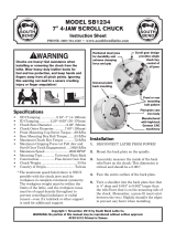
8" South Bend Precision Bench Lathe (Circa 1932)

-4-
For Machines Mfg. Since 8/11
Model SB1001 8K
™
Lathe
INTRODUCTION
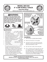
Identification
Serious personal injury could occur if
you connect the machine to power before
completing the setup process. DO NOT
connect power until instructed to do so later
in this manual.
Untrained users have an increased risk
of seriously injuring themselves with this
machine. Do not operate this machine until
you have understood this entire manual and
received proper training.
Control
Panel
Electrical
Cabinet
4-Way
Tool Post
Three V-Way
Bed
Longitudinal
Leadscrew
Thread
Dial
Half Nut
Lever
Headstock
D1-3
Spindle
3-Jaw
Chuck
Carriage
Handwheel
Compound Rest
Ball Handle
Quill
Lock Lever
Cross Slide
Ball Handle
Master Power
Switch
Quill
Ball Handle
Tailstock
End
Cover

For Machines Mfg. Since 8/11 Model SB1001 8K
™
Lathe
-5-
INTRODUCTION
Basic Controls &
Components
Refer to Figures 1–4 and the following
descriptions to become familiar with the features
and basic controls of this lathe. This knowledge
will be necessary to properly set up the lathe for
the test run and spindle break-in.
Master Power Switch
The switch shown in Figure 1 toggles incoming
power ON and OFF to the lathe controls.
To reduce the risk of
serious injury when using
this machine, read and
understand this entire
manual before beginning any
lathe operations.
Control Panel
Figure 1. Master power switch location.
Master
Power
Switch
A. Spindle Speed Dial: Controls the variable
spindle speed.
B. Emergency STOP Button: Cuts power to the
motor and control panel. Twist clockwise
until it pops out to reset.
C. Spindle Switch: When the master power
switch is ON, starts, stops, and reverses
spindle rotation.
D. Tachometer Display: Displays a digital
readout of the spindle speed.
Figure 2. Control panel components.
A
B
C
D
Always disconnect the lathe from power before
performing any adjustments, maintenance, or
service. Turning the master power switch to
OFF is NOT a safe alternative to completely
disconnecting the machine from power when
performing these tasks.

-6-
For Machines Mfg. Since 8/11
Model SB1001 8K
™
Lathe
INTRODUCTION
Carriage Tailstock
E. 4-Way Tool Post: Mounts up to four cutting
tools at once that can be individually indexed
to the workpiece.
F. Compound Rest Ball Handle: Moves the tool
toward and away from the workpiece at the
preset angle of the compound rest.
G. Carriage Lock: Secures the carriage in place
when the carriage should not move.
H. Thread Dial and Chart: Dial indicates when
to engage the half nut during threading
operations. Chart indicates on which thread
dial reading to engage the half nut for
specific inch thread pitches.
I. Half Nut Lever: Engages/disengages the half
nut for threading operations.
J. Carriage Handwheel: Moves the carriage
along the bedway.
K. Cross Slide Ball Handle: Moves the cross
slide toward and away from the workpiece.
Figure 3. Carriage components.
E
F
H
G
I
J
K
Figure 4. Tailstock components.
L
N
O
P
M
Q
L. Quill: Moves a tool or center toward or away
from the workpiece.
M. Tailstock Lock Nut: Secures the tailstock in
position along the bedway.
N. Quill Lock Lever: Secures the quill in
position.
O. Quill Ball Handle: Controls the movement of
the quill.
P. Offset Scale: Indicates the relative distance
of tailstock offset from the spindle centerline.
Q . Tailstock Offset Set Screw (1 of 2): Adjusts
the tailstock offset left or right from the
spindle centerline.

For Machines Mfg. Since 8/11 Model SB1001 8K
™
Lathe
-7-
INTRODUCTION
Model SB1001
Page 1 of 3
Model SB1001
8K, 8" x 18" Lathe
Product Dimensions
Weight.............................................................................................................................................................
268 lbs.
Width (side-to-side) x Depth (front-to-back) x Height..................................................................... 40 x 18 x 19 in.
Footprint (Length x Width)............................................................................................................. 35-1/2 x 6-1/4 in.
Shipping Dimensions
Type.......................................................................................................................................................... Wood Crate
Content..........................................................................................................................................................
Machine
Weight.............................................................................................................................................................
313 lbs.
Length x Width x Height................................................................................................................... 44 x 21 x 24 in.
Electrical
Power Requirement......................................................................................................... 120V, Single-Phase, 60 Hz
Prewired Voltage................................................................................................................................................ 120V
Full-Load Current Rating....................................................................................................................................
10A
Minimum Circuit Size..........................................................................................................................................
15A
Connection Type..................................................................................................................................... Cord & Plug
Power Cord Included............................................................................................................................................. Yes
Power Cord Length............................................................................................................................................... 5 ft.
Power Cord Gauge.........................................................................................................................................
14 AWG
Plug Included........................................................................................................................................................
Yes
Included Plug Type.............................................................................................................................................. 5-15
Switch Type................................................................................................................ ON/OFF Variable-Speed Dial
Motors
Main
Type................................................................................................................................................... Universal
Horsepower............................................................................................................................................
1.5 HP
Amps...........................................................................................................................................................
10A
Speed................................................................................................................................................ 3600 RPM
Power Transfer ................................................................................................................................ Belt Drive
Bearings................................................................................................ Shielded & Permanently Lubricated
Main Specifications
Operation Info
Swing Over Bed.........................................................................................................................................
8 in.
Distance Between Centers......................................................................................................................
18 in.
Swing Over Cross Slide............................................................................................................................. 5 in.
Swing Over Saddle.................................................................................................................................... 5 in.
Maximum Tool Bit Size.......................................................................................................................... 5/8 in.
Compound Travel................................................................................................................................
2-5/8 in.
Carriage Travel..................................................................................................................................
17-5/8 in.
Cross Slide Travel................................................................................................................................ 3-1/4 in.

-8-
For Machines Mfg. Since 8/11
Model SB1001 8K
™
Lathe
INTRODUCTION
Model SB1001
Page 2 of 3
Headstock Info
Spindle Bore........................................................................................................................................
1.125 in.
Spindle Taper.......................................................................................................................................... MT#3
Number of Spindle Speeds................................................................................................................. Variable
Spindle Speeds......................................................................................................................... 50 – 2300 RPM
Spindle Type..............................................................................................................................
D1-3 Camlock
Spindle Bearings............................................................................................
High-Precision Tapered Roller
Tailstock Info
Tailstock Quill Travel..........................................................................................................................
1-3/4 in.
Tailstock Taper........................................................................................................................................ MT#2
Tailstock Barrel Diameter................................................................................................................ 1.1875 in.
Threading Info
Number of Longitudinal Feeds....................................................................................................................... 9
Range of Longitudinal Feeds.....................................................................................
0.0030 – 0.0051 in./rev.
Number of Inch Threads............................................................................................................................... 12
Range of Inch Threads................................................................................................................... 10 – 32 TPI
Number of Metric Threads........................................................................................................................... 12
Range of Metric Threads............................................................................................................. 0.4 – 3.0 mm
Dimensions
Bed Width..................................................................................................................................................
6 in.
Carriage Leadscrew Diameter...............................................................................................................
5/8 in.
Leadscrew TPI......................................................................................................................................... 8 TPI
Carriage Leadscrew Length.............................................................................................................. 38-3/4 in.
Construction
Base.................................................................................................................................................... Cast Iron
Headstock..........................................................................................................................................
Cast Iron
End Gears.................................................................................................................................................
Steel
Bed.............................................................................................. Hardened and Precision-Ground Cast Iron
Body................................................................................................................................................... Cast Iron
Paint Type/Finish................................................................................................................................... Epoxy
Fluid Capacities
Headstock Capacity......................................................................................................................
1 – 2 Pumps
Headstock Fluid Type...........................................................
ISO 32 (eg. Grizzly T23963, Mobil DTE Light)
Other
Country of Origin ............................................................................................................................................. China
Warranty ......................................................................................................................................................... 1 Year
Approximate Assembly & Setup Time .......................................................................................................... 1 Hour
Sound Rating .................................................................................................................................................... 82 dB
ISO 9001 Factory ................................................................................................................................................... No
CSA, ETL, or UL Certified/Listed ........................................................................................................................ No
Features
Hardened and Ground Signature South Bend 3 V-Way Bed
Electronic Variable Speed Controls
4-Way Tool Post
Threading Dial Indicator
Emergency Stop Button
Inch and Metric Graduations on Tailstock Barrel

For Machines Mfg. Since 8/11 Model SB1001 8K
™
Lathe
-9-
SAFETY
Understanding Risks of Machinery
Operating all machinery and machining equipment can be dangerous or relatively safe depending
on how it is installed and maintained, and the operator's experience, common sense, risk awareness,
working conditions, and use of personal protective equipment (safety glasses, respirators, etc.).
The owner of this machinery or equipment is ultimately responsible for its safe use. This
responsibility includes proper installation in a safe environment, personnel training and usage
authorization, regular inspection and maintenance, manual availability and comprehension,
application of safety devices, integrity of cutting tools or accessories, and the usage of approved
personal protective equipment by all operators and bystanders.
The manufacturer of this machinery or equipment will not be held liable for injury or property
damage from negligence, improper training, machine modifications, or misuse. Failure to read,
understand, and follow the manual and safety labels may result in serious personal injury, including
amputation, broken bones, electrocution, or death.
The signals used in this manual to identify hazard levels are as follows:
Death or catastrophic
harm WILL occur.
Moderate injury or fire
MAY occur.
Death or catastrophic
harm COULD occur.
Machine or property
damage may occur.
Basic Machine Safety
Owner’s Manual: All machinery and machining
equipment presents serious injury hazards
to untrained users. To reduce the risk of
injury, anyone who uses THIS item MUST
read and understand this entire manual
before starting.
Personal Protective Equipment:
Operating or
servicing this item may expose the user
to flying debris, dust, smoke, dangerous
chemicals, or loud noises. These hazards
can result in eye injury, blindness, long-
term respiratory damage, poisoning,
cancer, reproductive harm or hearing loss.
Reduce your risks from these hazards
by wearing approved eye protection,
respirator, gloves, or hearing protection.
Trained/Supervised Operators Only: Untrained
users can seriously injure themselves
or bystanders. Only allow trained and
properly supervised personnel to operate
this item. Make sure safe operation
instructions are clearly understood. If
electrically powered, use padlocks and
master switches, and remove start switch
keys to prevent unauthorized use or
accidental starting.
Guards/Covers:
Accidental contact with
moving parts during operation may cause
severe entanglement, impact, cutting,
or crushing injuries. Reduce this risk by
keeping any included guards/covers/doors
installed, fully functional, and positioned
for maximum protection.

-10-
For Machines Mfg. Since 8/11
Model SB1001 8K
™
Lathe
SAFETY
Entanglement: Loose clothing, gloves, neckties,
jewelry or long hair may get caught in
moving parts, causing entanglement,
amputation, crushing, or strangulation.
Reduce this risk by removing/securing
these items so they cannot contact moving
parts.
Mental Alertness: Operating this item with
reduced mental alertness increases the
risk of accidental injury. Do not let a
temporary influence or distraction lead to a
permanent disability! Never operate when
under the influence of drugs/alcohol, when
tired, or otherwise distracted.
Safe Environment:
Operating electrically
powered equipment in a wet environment
may result in electrocution; operating near
highly flammable materials may result in a
fire or explosion. Only operate this item in
a dry location that is free from flammable
materials.
Electrical Connection: With electically powered
equipment, improper connections to the
power source may result in electrocution
or fire. Always adhere to all electrical
requirements and applicable codes when
connecting to the power source. Have all
work inspected by a qualified electrician to
minimize risk.
Disconnect Power: Adjusting or servicing
electrically powered equipment while it
is connected to the power source greatly
increases the risk of injury from accidental
startup. Always disconnect power
BEFORE any service or adjustments,
including changing blades or other tooling.
Secure Workpiece/Tooling:
Loose workpieces,
cutting tools, or rotating spindles can
become dangerous projectiles if not
secured or if they hit another object during
operation. Reduce the risk of this hazard
by verifying that all fastening devices are
properly secured and items attached to
spindles have enough clearance to safely
rotate.
Chuck Keys or Adjusting Tools:
Tools used to
adjust spindles, chucks, or any moving/
rotating parts will become dangerous
projectiles if left in place when the machine
is started. Reduce this risk by developing
the habit of always removing these tools
immediately after using them.
Work Area:
Clutter and dark shadows increase
the risks of accidental injury. Only operate
this item in a clean, non-glaring, and well-
lighted work area.
Properly Functioning Equipment:
Poorly
maintained, damaged, or malfunctioning
equipment has higher risks of causing
serious personal injury compared to
those that are properly maintained.
To reduce this risk, always maintain
this item to the highest standards and
promptly repair/service a damaged or
malfunctioning component. Always follow
the maintenance instructions included in
this documentation.
Unattended Operation:
Electrically powered
equipment that is left unattended while
running cannot be controlled and is
dangerous to bystanders. Always turn the
power OFF before walking away.
Health Hazards: Certain cutting fluids and
lubricants, or dust/smoke created when
cutting, may contain chemicals known to
the State of California to cause cancer,
respiratory problems, birth defects,
or other reproductive harm. Minimize
exposure to these chemicals by wearing
approved personal protective equipment
and operating in a well ventilated area.
Difficult Operations:
Attempting difficult
operations with which you are unfamiliar
increases the risk of injury. If you
experience difficulties performing the
intended operation, STOP! Seek an
alternative method to accomplish the
same task, ask a qualified expert how the
operation should be performed, or contact
our Technical Support for assistance.

For Machines Mfg. Since 8/11 Model SB1001 8K
™
Lathe
-11-
SAFETY
Additional Metal Lathe Safety
Speed Rates. Operating the lathe at the wrong
speed can cause nearby parts to break or the
workpiece to come loose, which will result in
dangerous projectiles that could cause severe
impact injuries. Large or non-concentric
workpieces must be turned at slow speeds.
Always use the appropriate feed and speed
rates.
Stopping Spindle by Hand. Stopping the spindle
by putting your hand on the workpiece
or chuck creates an extreme risk of
entanglement, impact, crushing, friction, or
cutting hazards. Never attempt to slow or
stop the lathe spindle with your hand. Allow
the spindle to come to a stop on its own or
use the brake.
Crashes. Aggressively driving the cutting tool
or other lathe components into the chuck
may cause an explosion of metal fragments,
which can result in severe impact injuries
and major damage to the lathe. Reduce this
risk by releasing automatic feeds after use,
not leaving lathe unattended, and checking
clearances before starting the lathe.
Make sure no part of the tool, tool holder,
compound rest, cross slide, or carriage will
contact the chuck during operation.
Long Stock Safety. Long stock can whip violently
if not properly supported, causing serious
impact injury and damage to the lathe.
Reduce this risk by supporting any stock
that extends from the chuck/headstock more
than three times its own diameter. Always
turn long stock at slow speeds.
Coolant Safety. Coolant is a very poisonous
biohazard that can cause personal injury
from skin contact alone. Incorrectly
positioned coolant nozzles can splash on
the operator or the floor, resulting in an
exposure or slipping hazard. To decrease
your risk, change coolant regularly and
position the nozzle where it will not splash
or end up on the floor.
Clearing Chips. Metal chips can easily cut bare
skin—even through a piece of cloth. Avoid
clearing chips by hand or with a rag. Use a
brush or vacuum to clear metal chips.
Chuck Key Safety. A chuck key left in the chuck
can become a deadly projectile when the
spindle is started. Always remove the chuck
key after using it. Develop a habit of not
taking your hand off of a chuck key unless it
is away from the machine.
Tool Selection. Cutting with an incorrect or
dull tool increases the risk of accidental
injury due to the extra force required for the
operation, which increases risk of breaking
or dislodging components that can cause
small shards of metal to become dangerous
projectiles. Always select the right cutter for
the job and make sure it is sharp. A correct,
sharp tool decreases strain and provides a
better finish.
Securing Workpiece. An improperly secured
workpiece can fly off the lathe spindle with
deadly force, which can result in a severe
impact injury. Make sure the workpiece is
properly secured in the chuck or faceplate
before starting the lathe.
Chucks. Chucks are very heavy and difficult to
grasp, which can lead to crushed fingers or
hands if mishandled. Get assistance when
handling chucks to reduce this risk. Protect
your hands and the precision-ground ways
by using a chuck cradle or piece of plywood
over the ways of the lathe when servicing
chucks.
Safe Clearances. Workpieces that crash into
other components on the lathe may throw
dangerous projectiles in all directions,
leading to impact injury and damaged
equipment. Before starting the spindle,
make sure the workpiece has adequate
clearance by hand-rotating it through its
entire range of motion. Also, check the tool
and tool post clearance, chuck clearance, and
saddle clearance.

-12-
For Machines Mfg. Since 8/11
Model SB1001 8K
™
Lathe
SAFETY
Additional Chuck Safety
Entanglement. Entanglement with a rotating
chuck can lead to death, amputation, broken
bones, or other serious injury. Never attempt
to slow or stop the lathe chuck by hand,
and always roll up long sleeves, tie back
long hair, and remove any jewelry or loose
apparel BEFORE operating.
Chuck Speed Rating. Excessive spindle speeds
greatly increase the risk of the workpiece or
chuck being thrown from the machine with
deadly force. Never use spindle speeds faster
than the chuck RPM rating or the safe limits
of your workpiece.
Using Correct Equipment. Many workpieces can
only be safely turned in a lathe if additional
support equipment, such as a tailstock or
steady rest, is used. If the operation is too
hazardous to be completed with the lathe or
existing equipment, the operator must have
enough experience to know when to use a
different machine or find a safer way.
Trained Operators Only. Using a chuck
incorrectly can result in workpieces coming
loose at high speeds and striking the
operator or bystanders with deadly force.
To reduce the risk of this hazard, read
and understand this document and seek
additional training from an experienced
chuck user before using a chuck.
Chuck Capacity. Avoid exceeding the capacity
of the chuck by clamping an oversized
workpiece. If the workpiece is too large to
safely clamp with the chuck, use a faceplate
or a larger chuck if possible. Otherwise, the
workpiece could be thrown from the lathe
during operation, resulting in serious impact
injury or death.
Clamping Force. Inadequate clamping force
can lead to the workpiece being thrown
from the chuck and striking the operator
or bystanders. Maximum clamping force
is achieved when the chuck is properly
maintained and lubricated, all jaws are
fully engaged with the workpiece, and the
maximum chuck clamping diameter is not
exceeded.
Proper Maintenance.
All chucks must be properly
maintained and lubricated to achieve
maximum clamping force and withstand
the rigors of centrifugal force. To reduce
the risk of a thrown workpiece, follow all
maintenance intervals and instructions in
this document.
Disconnect Power. Serious entanglement or
impact injuries could occur if the lathe is
started while you are adjusting, servicing, or
installing the chuck. Always disconnect the
lathe from power before performing these
procedures.

For Machines Mfg. Since 8/11 Model SB1001 8K
™
Lathe
-13-
PREPARATION
Preparation Overview Required for Setup
The purpose of the preparation section is to help
you prepare your machine for operation. The list
below outlines this basic process. Specific steps
for each of these points will be covered in detail
later in this section.
The typical preparation process is as follows:
1. Unpack the lathe and inventory the contents
of the box/crate.
2. Clean the lathe and its components.
3. Identify an acceptable location for the lathe
and move it to that location.
4. Level the lathe and bolt it to a workbench or
stand.
5. Assemble the loose components and make
any necessary adjustments or inspections to
ensure the lathe is ready for operation.
6. Check/lubricate the lathe.
7. Connect the lathe to the power source.
8. Test run the lathe to make sure it functions
properly.
9. Perform the spindle break-in procedure to
prepare the lathe for operation.
To complete the preparation process, you will
need the following items:
For Lifting and Moving
• Additional people for lifting the lathe (at
least two)
For Power Connection
• A power source that meets the minimum
circuit requirements for this machine (review
Power Supply Requirements on the next
page for details)
For Cleaning & Assembly
• Cotton rags
• Mineral spirits
• Quality metal protectant oil
• Safety glasses
• Bench mounting hardware as needed
• Precision level

-14-
For Machines Mfg. Since 8/11
Model SB1001 8K
™
Lathe
PREPARATION
Power Supply
Requirements
Availability
The full-load current rating is the amperage
a machine draws at 100% of the rated output
power. On machines with multiple motors, this is
the amperage drawn by the largest motor or sum
of all motors and electrical devices that might
operate at one time during normal operations.
Full-Load Current Rating
Full-Load Rating .................................. 10 Amps
For your own safety and protection of property,
consult an electrician if you are unsure about
wiring practices or applicable electrical codes.
Serious injury could occur if you connect
the machine to power before completing the
setup process. DO NOT connect to power until
instructed later in this manual.
Before installing the machine, consider the
availability and proximity of the required power
supply circuit. If an existing circuit does not meet
the requirements for this machine, a new circuit
must be installed.
To minimize the risk of electrocution, fire,
or equipment damage, installation work and
electrical wiring must be done by an electrician
or qualified service personnel in accordance with
all applicable codes.
The full-load current is not the maximum
amount of amps that the machine will draw. If
the machine is overloaded, it will draw additional
amps beyond the full-load rating.
If the machine is overloaded for a sufficient
length of time, damage, overheating, or fire may
result—especially if connected to an undersized
circuit. To reduce the risk of these hazards,
avoid overloading the machine during operation
and make sure it is connected to a power supply
circuit that meets the requirements in the
following section.
Circuit Requirements
Note: The circuit requirements in this manual
are for
a dedicated circuit—where only one
machine will be running at a time. If this
machine will be connected to a shared circuit
where multiple machines will be running at
the same time, consult a qualified electrician to
ensure the circuit is properly sized.
A power supply circuit includes all electrical
equipment between the main breaker box or fuse
panel in your building and the incoming power
connections inside the machine. This circuit
must be safely sized to handle the full-load
current that may be drawn from the machine for
an extended period of time. (If this machine is
connected to a circuit protected by fuses, use a
time delay fuse marked D.)
Nominal Voltage ............................... 110V/120V
Cycle .............................................................60 Hz
Phase ..............................................Single-Phase
Circuit Rating....................................... 15 Amps
Plug/Receptacle ...............................NEMA 5-15
This machine is prewired to operate on a 110V
power supply circuit that has a verified ground
and meets the following requirements:

For Machines Mfg. Since 8/11 Model SB1001 8K
™
Lathe
-15-
PREPARATION
Grounding Requirements Extension Cords
We do not recommend using an extension cord
with this machine. If you must use an extension
cord, only use it if absolutely necessary and only
on a temporary basis.
Extension cords cause voltage drop, which may
damage electrical components and shorten motor
life. Voltage drop increases as the extension cord
size gets longer and the wire gauge size gets
smaller (higher gauge numbers indicate smaller
sizes).
Any extension cord used with this machine
must contain a ground wire, match the required
plug and receptacle, and meet the following
requirements:
Minimum Gauge Size ............................14 AWG
Maximum Length (Shorter is Better) ....50 ft.
This machine must be grounded! In the event
of
certain types of malfunctions or breakdowns,
grounding provides a path of least resistance
for electric current
in order to reduce the risk of
electric shock.
This machine is equipped with a power cord
that has an equipment-grounding wire and a
grounding plug (see Figure 5). The plug must
only be inserted into a matching receptacle
(outlet) that is properly installed and grounded
in accordance with all local codes and ordinances.
Figure 5. Typical 5-15 plug and receptacle.
Grounding Prong
Current Carrying Prongs
5-15 PLUG
GROUNDED
5-15 RECEPTACLE
SHOCK HAZARD!
Two-prong outlets do not meet the grounding
requirements for this machine. Do not modify
or use an adapter on the plug provided—if it
will not fit the outlet, have an electrician or
qualified service personnel install the proper
outlet with a verified ground.

-16 -
For Machines Mfg. Since 8/11
Model SB1001 8K
™
Lathe
PREPARATION
Unpacking
This item was carefully packaged to prevent
damage during transport. If you discover any
damage, please immediately call Customer
Service at
(360) 734-1540 for advice. You may
need to file a freight claim, so save the containers
and all packing materials for possible inspection
by the carrier or its agent.
Inventory
Tool Box Inventory (Figures 6–7) Qty
A. Tool Box .......................................................... 1
B. Timing-Belt Pulley 28T ................................. 1
C. Timing-Belt Pulley 27T .................................1
D. Timing-Belt Pulley 26T ................................. 1
E. Timing-Belt Pulley 24T .................................1
F. Timing-Belt Pulley 22T ................................. 1
G. Timing-Belt Pulley 21T .................................1
H. Timing-Belt Pulley 20T .................................1
I. Timing-Belt Pulley 19T .................................1
J. Timing-Belt Pulley 18T ................................. 1
K. Timing-Belt Pulley 16T .................................1
L. Timing-Belt Pulley 38T .................................1
M. Timing-Belt Pulley 32T .................................1
N. Power Cord 16G 3C 72" M/F 5-15 .................1
O. 3-Jaw Chuck External Jaw Set ..................... 1
P. Chuck Key ......................................................1
Q. Wrench 13mm ................................................1
R. Combo Wrench 14 x 17mm ............................1
S. Hex Wrench Set, 2, 3, 4, 5, 6, 8mm ......1 Each
T. Tapered Spindle Sleeve MT#4.5–MT#3 ........1
U. Dead Center MT#2 ......................................... 1
V. Dead Center MT#3 ......................................... 1
W. Grease Gun .....................................................1
X. Rubber Mounting Gasket ..............................1
Y. Timing Belt 140XL ......................................... 1
Z . Timing Belt 160XL .........................................1
AA. Fuses Time-Delay15A (T15L250V) ............... 5
Installed & Not Shown Qty
• 3-Jaw Chuck Assembly 4" .............................1
Figure 6. Toolbox and timing-belt pulleys.
A
B
C
D E
L
F
G
H
I
J
K
M
Figure 7. Additional small items.
N
O
P
Q
R
S
T
U
V
W
X
Y
Z
AA

For Machines Mfg. Since 8/11 Model SB1001 8K
™
Lathe
-17-
PREPARATION
The unpainted surfaces are coated
at the factory
with a heavy-duty rust preventative that
prevents corrosion during shipment and
storage.
The benefit of this rust preventative is that it
works very well. The downside is that it
can be
time-consuming
to thoroughly remove.
Be patient and do a careful job when
cleaning
and removing the rust preventative
. The time
you spend doing this will reward you with
smooth
-sliding parts and a better appreciation
for the proper care of
the unpainted surfaces.
Although there are many ways to successfully
remove the rust preventative, the
following
process works well in most situations
.
Before cleaning, gather the following:
• Disposable
rags
• Cleaner/degreaser
(certain citrus-based
degreasers work extremely well and they
have non-toxic fumes)
• Safety
glasses&disposablegloves
Note:
Automotive degreasers, mineral spirits, or
WD•40
canbeusedtoremoverustpreventative.
Before using these products, though, test them
on an inconspicuous area of a painted surface to
make sure they will not damage it.
Basic steps for removing rust preventative:
1. Put on safety glasses and disposable gloves.
2. Coatallsurfacesthathaverustpreventative
with a liberal amount of your cleaner or
degreaser and let them soak for a few
minutes.
3. Wipe off the surfaces. If your cleaner or
degreaser is effective, the rust preventative
will wipe off easily.
Note:
To clean off thick coats of rust preventative
on flat surfaces, such as beds or tables, use
aPLASTICpaintscrapertoscrapeoffthe
majority of the coating before wiping it off
withyourrag.(Donotuseametalscraperor
it may scratch the surface.)
4. Repeat Steps 2–3 as necessary until clean,
then coat all unpainted surfaces with a
quality metal protectant or light oil to
prevent rust.
GAS
Gasoline and petroleum
products have low flash
points and can explode
or cause fire if used for
cleaning. Avoid using these
products to remove rust
preventative.
Many cleaning solvents are
toxic if inhaled. Minimize
your risk by only using
these products in a well
ventilated area.
Avoid chlorine-based solvents, such as
acetone or brake parts cleaner that may
damage painted surfaces. Always follow the
manufacturer’s instructions when using any
type of cleaning product.
Cleaning & Protecting

-18-
For Machines Mfg. Since 8/11
Model SB1001 8K
™
Lathe
PREPARATION
Wall
30" Minimum
for Maintenance
44"
16"
Figure 8. Clearances.
Physical Environment
Electrical Installation
Lighting
Weight Load
Space Allocation
Weight Load
Refer to the Machine Specifications for the
weight of your machine. Make sure that the
surface upon which the machine is placed will
bear the weight of the machine, additional
equipment that may be installed on the machine,
and the heaviest workpiece that will be used.
Additionally, consider the weight of the operator
and any dynamic loading that may occur when
operating the machine.
Space Allocation
Consider the largest size of workpiece that will
be processed through this machine and provide
enough space around the machine for adequate
operator material handling or the installation
of auxiliary equipment. With permanent
installations, leave enough space around
the machine to open or remove doors/covers
as required by the maintenance and service
described in this manual.
Physical Environment
The physical environment where your machine
is operated is important for safe operation and
longevity of
parts. For best results, operate this
machine in a dry environment that is free from
excessive moisture, hazardous
or flammable
chemicals, airborne abrasives, or extreme
conditions. Extreme conditions for this type
of machinery are generally those where the
ambient temperature
is outside the range of 41°–
104°F; the relative humidity
is outside the range
of
20–95% (non-condensing); or the environment
is subject to vibration, shocks, or bumps.
Electrical Installation
Place this machine near an existing power
source. Make sure all power cords are protected
from traffic, material handling, moisture,
chemicals, or other hazards. Make sure to leave
access to a means of disconnecting the power
source or engaging a lockout/tagout device.
Lighting
Lighting around the machine must be adequate
enough to perform operations safely. Shadows,
glare, or strobe effects that may distract or
impede the operator must be eliminated.
Children or untrained
people may be seriously
injured by this machine.
Only install in an access
restricted location.
Location
/