Page is loading ...

ARF
ALMOST-READY-TO-FLY
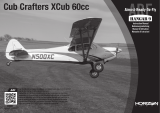
Clipped Wing Cub 250
Instruction Manual
Bedienungsanleitung
Manuel d’utilisation
Manuale di Istruzioni

2
EFL Clipped Wing Cub
SAFETY WARNINGS AND PRECAUTIONS
Read and follow all instructions and safety precautions
before use. Improper use can result in fi re, serious injury
and damage to property.
Components
Use only with compatible components. Should any
compatibility questions exist, please refer to the product
instructions, component instructions or contact the
appropriate Horizon Hobby offi ce.
Flight
Fly only in open areas to ensure safety. It is
recommended fl ying be done at radio control fl ying
fi elds. Consult local ordinances before choosing a fl ying
location.
Propeller
Keep loose items that can become entangled in
the propeller away from the prop. This includes
loose clothing or other objects such as pencils and
screwdrivers. Keep your hands away from the propeller
as injury can occur.
Batteries
Always follow the manufacturer’s instructions when using
and disposing of any batteries. Mishandling of Li-Po
batteries can result in fi re causing serious injury and
damage.
Small Parts
This kit includes small parts and should not be left
unattended near children as choking and serious injury
could result.
SAFE OPERATING RECOMMENDATIONS
• Inspect your model before every fl ight to ensure it is
airworthy.
• Be aware of any other radio frequency user who may
present an interference problem.
• Always be courteous and respectful of other users in
your selected fl ight area.
• Choose an area clear of obstacles and large enough to
safely accomodate your fl ying activity.
• Make sure this area is clear of friends and spectators
prior to launching your aircraft.
• Be aware of other activities in the vicinity of your fl ight
path that could cause potential confl ict.
• Carefully plan your fl ight path prior to launch.
• Abide by any and all established AMA National Model
Aircraft Safety Code.
REGARDING MOTOR AND BATTERY
SELECTION
This model has been tested using the components
listed in the Power Systems section of this manual.
Using components that exceed the output of the listed
components may place excessive loads on the airframe.
This could result in the failure of the airframe in high-
speed or high-load situations.
NOTICE
All instructions, warranties and other collateral documents are subject to change at the sole discretion of Horizon
Hobby, LLC. For up-to-date product literature, visit horizonhobby. com and click on the support tab for this product.
Meaning of Special Language
The following terms are used throughout the product literature to indicate various levels of potential harm when
operating this product:
NOTICE: Procedures, which if not properly followed, create a possibility of physical property damage AND a little
or no possibility of injury.
CAUTION: Procedures, which if not properly followed, create the probability of physical property damage AND a
possibility of serious injury.
WARNING: Procedures, which if not properly followed, create the probability of property damage, collateral
damage, and serious injury OR create a high probability of superfi cial injury.
WARNING: Read the ENTIRE instruction manual to become familiar with the features of the product
before operating. Failure to operate the product correctly can result in damage to the product, personal
property and cause serious injury.
This is a sophisticated hobby product. It must be operated with caution and common sense and requires some
basic mechanical ability. Failure to operate this Product in a safe and responsible manner could result in injury
or damage to the product or other property. This product is not intended for use by children without direct adult
supervision. Do not use with incompatible components or alter this product in any way outside of the instructions
provided by Horizon Hobby, LLC. This manual contains instructions for safety, operation and maintenance. It is
essential to read and follow all the instructions and warnings in the manual, prior to assembly, setup or use, in
order to operate correctly and avoid damage or serious injury.
Age Recommendation: Not for children under 14 years. This is not a toy.
USING THE MANUAL
This manual is divided into sections to help make assembly easier to understand. Boxes () have been placed next
to each step. These help keep track of steps that have been completed.

6
EFL Clipped Wing Cub
30.7 in (780mm)
168 sq in (10.9 dm2)
23.7 in (600mm)
8.95–9.30 oz (254–263 g)
Electric Power Power:
Power 250 Brushless
Elektro Antrieb Power:
Power 250 Brushless
Moteur électrique (EP):
Power 250 Brushless
Motore elettrico:
Power 250 Brushless
4-channel (or greater) with 4 servos
4-Kanal (oder größer) mit 4 Servos
4 voies (ou plus) avec 4 servos
a 4 canali (o più) con 4 servo
SPECIFICATIONS•SPEZIFIKATIONEN•
SPÉCIFICATIONS•SPECIFICHE
LARGE PARTS LAYOUT•BAUTEILE (OHNE KLEINTEILE)•GRANDES PIÈCES•SCHEMA DEI COMPONENTI GRANDI
2
8
1
3
5
6
7
2
9
4
4

7
EFL Clipped Wing Cub
REPLACEMENT PARTS•ERSATZTEILE•PIÈCES DE RECHANGE•PEZZI DI RICAMBIO
Part English Deutsch Français Italiano
1. EFL505501 Fuselage Rumpf Fuselage Fusoliera
2. EFL505502 Wing Panels, Left and Right Tragfl ächen Aile gauche et droite Pannelli alari, Sinistro e Destro
3. EFL505503 Tail Set Heck Empennages Set coda
4. EFL505504 Landing Gear & Wheel Pants Fahrwerk u. Radschuhe Train d’atterrissage avec carénages de roues Carrello e carenature ruote
5. EFL505505 Cowling Motorhaube Capot moteur Carenatura
6. EFL505506 Windshields Fenster Set Jeu de fenêtres Set fi nestrature
7. EFL505508 Main Struts Fahrwerksstreben Haubans d’aile Montanti principali
8. EFL505509 Wing Tube Tragfl ächenverbinder Clé d’aile Tubo dell’ala
9. EFL5031 Main Wheel Set: 37mm 37mm Reifen Routes de 37mm Ruote da 37mm
SMALL PARTS (NOT SHOWN)•KLEINTEILE (NICHT ABGEBILDET)•PETITES PIÈCES (NON REPRÉSENTÉES)•PARTI DI PICCOLE DIMENSIONI (NON MOSTRATE)
EFL505507 Hardware Kleinteile Set Sachet de visserie Set dei pezzi
EFL5034 Pushrods Schubstangen Tiges Barrette comandi
REQUIRED RADIO EQUIPMENT•ERFORDERLICHE RC AUSRÜSTUNG•EQUIPEMENT RADIO REQUIS•APPARECCHIATURE RADIO
SPMAR6335 AR6335 AS3X
®
Receiver AR6335 6-Kanal AS3X Nanolite Empfänger Récepteur AR6335 AS3X Ricevitore AR6335 AS3X
EFLRDS35 (4) 3.5-Gram DS35 Digital Super Sub-Micro Servo 3.5-Gram DS35 Digital Super Sub-Micro Servo Super sub-micro servo digital DS35, 3.5g Servo digitale super sub micro 3.5-Gram DS35
SPMEXJST3UL (2) 3 inch JST Extension Ultra Lightweight 3 inch JST Verlängerung Ultraleicht Rallonge JST ultra légère, 7.5cm Prolunga ultra leggera 7,5cm JST
SPMEXJST6UL (2) 6 inch JST Extension Ultra Lightweight 6 inch JST Verlängerung Ultraleicht Rallonge JST ultra légère, 15cm Prolunga ultra leggera 15cm JST
POWER SYSTEM•ANTRIEB•MOTORISATION•SISTEMA PROPULSIVO
EFLM1130 Power 250 Brushless Outrunner Motor, 2200Kv Power 250 Brushless Außenläufer Motor, 2200Kv Moteur Power 250 brushless à cage Power 250 motore brushless a cassa
tournante, 2200Kv rotante, 2200Kv
EFLA1010 10-Amp Pro Brushless ESC E-fl ite 10-Amp Pro Brushless Regler Contrôleur brushless Pro 10A ESC brushless Pro 10 A
EFLB4502SJ30 450mAh 2S 7.4V 30C LiPo, 18AWG JST E-fl ite 450mAh 2S 7.4V 30C LiPo, 18AWG JST Batterie LI-Po 2S 7.4V 450mA 30C, prise JST 450mAh 2S 7.4V 30C LiPo, 18AWG JST
APC07040E Electric Propeller, 7 x 4 Elektro Propeller, 7 x 4 Hélice électrique, 7 x 4 Elica elettrica sottile, 7 x 4

8
EFL Clipped Wing Cub
REQUIRED ADHESIVES•ERFORDERLICHE KLEBSTOFFE•TYPES DE COLLES•ADESIVI NECESSARI
PAAPT35 15-Minute Epoxy 15 Minuten Epoxy Époxy 15 minutes Colla epoxy 15 minuti
PAAPT09 Thin CA Sekundenkleber dünnfl üssig Colle cyano fi ne Sottile CA
PAAPT03 Medium CA Sekundenkleber mittel Colle cyano moyenne Medio CA
PAAPT15 Zip Kicker Aerosol, 2 oz Zip Kicker Aerosol, 2 oz Accélérateur Zip Kicker en bombe, 59ml Zip Kicker Spray, 60g
PAAPT42 Threadlock Schraubensicherungslack Frein-fi let Frenafi letti
OPTIONAL ITEMS•OPTIONALE TEILE•ELÉMENTS OPTIONNELS•ARTICOLI OPZIONALI
EFLA110 Power Meter E-fl ite Lastmessgerät Wattmètre Misuratore di potenza
DYNC2015 Prophet
™
Precept
™
80W LCD AC/DC Dynamite Prophet Precept 80W LCD Chargeur AC/DC Prophet Precept LCD 80W Caricabatterie Prophet Precept 80W LCD AC/DC
Battery Charger ACDC Ladegerät, EU
REQUIRED TOOLS•BENÖTIGTES WERKZEUG•OUTILS REQUIS•ATTREZZI NECESSARI
English Deutsch Français Italiano
Drill bit: 3/64-inch, 1/16-inch, 9/32-inch Bohrer: 1,2mm, 1,5 mm, 7mm Foret : 1,2mm, 1,5 mm, 7mm Punte per trapano: 1,2mm, 1,5 mm, 7mm
Hemostat Klemme Pince Hemostat Pinzetta
Hex wrench: .050 inch Inbusschlüssel: .050 inch Tournevis hexagonal : .050 inch Chiave esag.: .050 inch
Hobby knife: #11 blade Hobbymesser mit # 11 Klinge Couteau : Lame numéro 11 Taglierino: #11 lama
Low-tack tape Klebeband m. geringer Klebekraft Adhésif de masquage Nastro a bassa aderenza
Pencil Stift Crayon à papier Matita
Phillips screwdriver: #0 Phillips Schraubendreher: #0 Tournevis cruciforme: #0 Cacciavite a croce: #0
Pin vise Handbohrer Porte-forets Trapano manuale
Pliers Zange Pince Pinze
Propeller reamer Propellerfeile Alésoir d’hélice Alesatore per eliche
Ruler Lineal Réglet Righello
Sandpaper Schleifpapier Papier de verre Carta vetrata
Scissors Schere Ciseaux Forbici
Side cutters Seitenschneider Pince coupante Lama laterale
String or dental fl oss Garn / Zahnseide Ficelle ou fi l dentaire Cordino o fi lo interdentale
T-pins T- Nadeln Epingles Spilli a T

10
EFL Clipped Wing Cub
BEFORE STARTING ASSEMBLY
• Remove parts from bag.
• Inspect fuselage, wing panels, rudder and stabilizer
for damage.
• If you fi nd damaged or missing parts, contact your
place of purchase.
If you fi nd any wrinkles in the covering, use a heat gun
(HAN100) and covering glove (HAN150) or covering iron
(HAN101) with a sealing iron sock (HAN141) to remove
them. Use caution while working around areas where the
colors overlap to prevent separating the colors.
This model has been designed to keep the weight at a
minimum. When tightening the covering, work carefully
to avoid inducing warps or changing the alignment of the
structure.
• Charge transmitter and receiver batteries.
• Center trims and sticks on your transmitter.
• For a computer radio, create a model memory for this
particular model.
• Bind your transmitter and receiver, using your radio
system’s instructions.
IMPORTANT: Rebind the radio system once all
control throws are set. This will keep the servos from
moving to their endpoints until the transmitter and
receiver connect. It will also guarantee the servo
reversal settings are saved in the radio system.
VOR DEM ZUSAMMENBAU
• Entnehmen Sie zur Überprüfung jedes Teil der
Verpackung.
• Überprüfen Sie den Rumpf, Tragfl ächen, Seiten- und
Höhenruder auf Beschädigung.
• Sollten Sie beschädigte oder fehlende Teile feststellen,
kontaktieren Sie bitte den Verkäufer.
Zum Entfernen von Falten in der Bespannung verwenden
Sie den Heißluftfön (HAN100) und Bespannhandschuh
(HAN150) oder das Folienbügeleisen (HAN141). Bitte
achten Sie bei überlappenden Farben, dass Sie diese sich
bei dem Bearbeitung nicht trennen.
Dieses Modell wurde auf geringstes Gewicht konstruiert.
Bitte beachten Sie bei dem Spannen der Bespannfolie,
dass sie nicht die Ausrichtung der Struktur verändern.
• Laden des Senders und Empfängers.
• Zentrieren der Trimmungen und Sticks auf dem
Sender.
• Sollten Sie einen Computersender verwenden,
resetten Sie einen Speicherplatz und benennen ihn
nach dem Modell.
• Sender und Empfänger jetzt nach den Bindeanweisung
des Herstellers zu binden.
WICHTIG: Wir empfehlen dringend nachdem alle
Einstellungen vorgenommen worden sind, das Modell
neu zu binden. Dieses verhindert, dass die Servos
in die Endanschläge laufen bevor sich Sender und
Empfänger verbunden haben. Es garantiert auch, dass die
Servoreverseeinstellungen in der RC Anlage gesichert sind.
AVANT DE COMMENCER
L’ASSEMBLAGE
• Retirez toutes les pièces des sachets pour les
inspecter.
• Inspectez soigneusement le fuselage, les ailes et les
empennages.
• Si un élément est endommagé, contactez votre
revendeur.
Si l’entoilage présente des plis, vous pouvez les
lisser en utilisant le pistolet à air chaud (HAN100)
et le gant (HAN150) ou le fer à entoiler (HAN101)
avec la chaussette de protection (HAN141). Agissez
soigneusement dans les zones où plusieurs couleurs
d’entoilage sont superposées afi n d’éviter de les séparer.
Ce modèle a été conçu pour obtenir une masse
minimale. Quand vous retendez l’entoilage, prenez soin
de ne pas déformer la structure.
• ll est recommandé de préparer tous les éléments du
système de la radio.
• Cela inclut, la charge des batteries comme la mise au
neutre des trims et des manches de votre émetteur.
• Si vous utilisez une radio programmable, sélectionnez
une mémoire libre afi n d’y enregistrer les paramètres
de ce modèle.
• Nous vous recommandons d’affecter maintenant le
récepteur à l’émetteur en suivant les instructions
fournies avec votre radio.
IMPORTANT: Il est hautement recommandé de
ré-affecter le système une fois que les courses seront
réglées. Cela empêchera les servos d’aller en butée lors
de la connexion du système. Cela garantit également que
la direction des servos est enregistrée dans l’émetteur.
PRIMA DI INIZIARE IL MONTAGGIO
• Togliere tutti i pezzi dalla scatola.
• Verifi care che la fusoliera, l’ala e i piani di coda non
siano danneggiati.
• Se si trovano parti danneggiate, contattare il negozio
da cui è stato acquistato.
Se si trovano delle pieghe nella ricopertura, si possono
togliere usando una pistola ad aria calda (HAN100) e
guanto per ricopertura (HAN150), oppure un ferro per
ricopertura (HAN101) con la sua calza di protezione
(HAN141). Usare cautela quando si lavora in aree del
rivestimento dove ci sono dei colori sovrapposti, per
evitare la loro separazione.
Questo modello è stato progettato per mantenere al
minimo il suo peso. Quando si tende il rivestimento,
bisogna lavorare con attenzione per non fare delle grinze
o modifi care l’allineamento delle strutture (svergolature).
• Caricare il trasmettitore e la batteria di volo.
• Centrare stick e trim sul trasmettitore.
• Con una radio computerizzata creare una nuova
memoria per questo modello.
• Facendo riferimento alle istruzioni del radiocomando,
connettere (bind) trasmettitore e ricevitore.
IMPORTANTE: Ripetere la procedura di connessione
una volta regolate le corse, per evitare che i servi vadano
a fi ne corsa. Garantirà anche che le impostazioni di
inversione del servo vengano salvate nel sistema radio.

11
EFL Clipped Wing Cub
1
Use the radio system to center the rudder and elevator
servos. Install the servo arm on the servo as well as the
servo mount.
Zentrieren Sie die Höhen- und Seitenruderservos mit
der Fernsteuerung. Montieren Sie den Servoarm und die
Servohalter.
Utilisez la radio pour mettre au neutre les servos de
dérive et de profondeur. Installez les bras et les supports
sur les servos.
Usare il radiocomando per centrare i servi di timone ed
elevatore. Montare sui servi le squadrette e i supporti.
2
x2
x2
Attach the pushrod connector to the servo arm from the
rudder and elevator servos. Use a pin vise and 1/16-inch
(1.5mm) drill bit to enlarge the hole in the servo arm for
the connector. Make sure the connector can move freely
without excessive play when installed.
Vergrößern Sie mit einem 1,5mm Bohrer das
markierte Loch auf dem Servoarm. Setzen Sie den
Gestängeanschluß auf den Servoarm des Seiten- und
Höhenruderservos. Bitte achten Sie darauf, dass sich
der Anschluss ohne viel Spiel frei drehen kann.
Utilisez un forêt de 1.5mm pour agrandir le trou des
bras de servo situé à 10mm du centre. Fixez les
connecteurs de tringleries dans ces trous, assurez-vous
qu’il peut tourner librement sans jeu excessif.
Fissare alla squadretta del servo il connettore per
l’astina di comando di elevatore e timone. Con una
punta da 1,5mm allargare il foro sulla squadretta per
il connettore. Accertarsi che il connettore si possa
muovere liberamente senza troppo gioco.
3
x4
Thread a servo mounting screw into each of the holes in
the elevator and rudder servo mounting holes. Remove
the screws before proceeding.
Drehen Sie eine Servobefestigungsschraube in jedes der
Löcher der Servohalterungen. Drehen Sie die Schraube
wieder heraus.
Vissez une vis de fi xation de servo dans chaque trou
de fi xation des servos de profondeur et de dérive.
Retirez les vis.
Avvitare una vite in ognuno dei fori del supporto. Togliere
le viti prima di procedere.
4
x4
Apply a small amount of thin CA to harden the threads
made in the previous step.
Geben Sie einen kleinen Tropfen dünnfl üssigen
Sekundenkleber in die Gewindelöcher um diese zu härten.
Appliquer une petite quantité de colle cyano fi ne pour
durcir les fi letages faits lors de l’étape précédente.
Mettere una piccola quantità di colla CA nei fori, per
indurire il fi letto fatto nel passaggio precedente.
RUDDER AND ELEVATOR SERVO INSTALLATION•EINBAU VON HÖHEN UND SEITENRUDERSERVO•
INSTALLATION DES SERVOS DE PROFONDEUR ET DE DÉRIVE•INSTALLAZIONE SERVI TIMONE ED ELEVATORE

12
EFL Clipped Wing Cub
5
Secure the rudder and elevator servos in the fuselage with
the servo output facing toward the rear of the fuselage.
Schrauben Sie das Seitenruder- und Höhenruderservo
mit dem Abtrieb zum Heck zeigend in den Rumpf ein.
Fixez les servos de profondeur et de dérive à l’intérieur
du fuselage, les têtes des servos doivent être orientée
vers l’arrière du fuselage.
Fissare in fusoliera i servi di elevatore e timone con il perno
di uscita rivolto verso la parte posteriore della fusoliera.
7
x2
Secure the pushrod wire to the outer hole of the control
horn using the pushrod keeper.
Sichern Sie den Anschluß mit dem Clip in dem äußersten
Loch des Ruderhorns.
Sécurisez la liaison entre la tringlerie et le trou extérieur
du guignol de la dérive à l’aide du verrou.
Fissare l’astina nel foro più esterno della squadretta con
il suo fermo.
8
M2 x 4
x1
Center the rudder and rudder servo. Use the M2 x
4 machine screw to secure the pushrod wire to the
connector at the servo arm.
Zentrieren Sie das Seitenruder und Seitenruderservo.
Drehen Sie die M2 x 4 Schraube im Gestängeanschluß fest.
Mettez les servos de dérive et de profondeur au neutre.
Utilisez les vis M2x4 pour bloquer la tringlerie dans les
connecteurs fi xés aux bras de servos.
Centrare il timone e il suo servo. Fissare l’astina
al connettore già sulla squadretta, con una vite da
M2x4mm.
6
Slide the 17-inch (432mm) rudder pushrod into the pre-
installed tube in the fuselage. Guide the pushrod through
the hole in the pushrod on the rudder servo.
Schieben Sie das 432mm lange Seitenrudergestänge
in das Röhrchen im Rumpf und dann weiter in den
Gestängeanschluß des Seitenruderservos.
Glissez la tringlerie de dérive (432mm) dans la gaine
pré-installée dans le fuselage. Glissez la tringlerie dans
le trou du connecteur du servo de dérive.
Inserire l’astina di comando nel tubetto già installato in
fusoliera e guidarla fi no al servo del timone.

13
EFL Clipped Wing Cub
9
M2 x 4
x1
Repeat Steps 6 through 8 to install and connect the
16
3
/
4
inch (425mm) elevator pushrod.
Wiederholen Sie die Schritte 6 bis 8 um das 425mm
lange Höhenrudergestänge zu montieren.
Répétez les étapes de 6 à 8 pour installer et connecter
la tringlerie (425mm) de profondeur.
Ripetere i passi da 6 a 8 per montare e collegare l’astina
di comando da 425mm per l’elevatore.
2
L
R
L
R
Lightly sand the inside of the wheel pants around the
hole in the sides of the pant. Sand both the left and right
sides of the pant to prepare for the installation of the
wheel pant spacers.
Schleifen Sie die linke und rechte Seite der Öffnung
beider Radschuhe zur Vorbereitung des Einsetzen der
Distanzstücke etwas an.
Poncez légèrement l’intérieur des carénages de roues.
Poncez le côté gauche et le droit de chaque carénage
pour préparer l’installation des entretoises.
Carteggiare leggermente l’interno della carenatura
ruote intorno ai fori sui due lati. Carteggiare anche
entrambi i lati delle carenature per preparare
l’installazione dei distanziali.
1
Fit the main landing gear into the slots in the bottom
of the fuselage. Use a small amount of CA to glue the
landing gear into the fuselage.
Setzen Sie das Fahrwerk in die Schlitze auf der
Unterseite des Rumpfes und kleben es mit etwas
Sekundenkleber fest.
Glissez le train d’atterrissage dans les rainures situées
sous le fuselage. Utilisez une petite quantité de colle CA
pour fi xer le train d’atterrissage au fuselage.
Adattare il carrello principale nelle sue fessure sulla
parte inferiore della fusoliera. Incollare il carrello alla
fusoliera con poca colla CA.
3
x4
Lightly sand the wheel pant spacers in preparation for
their installation.
Schleifen Sie Distanzstücke der Radschuhe vor dem
Einbau an.
Poncez légèrement l’entretoise de carénage de roue pour
préparer l’installation.
Carteggiare leggermente i distanziali per le carenature.
LANDING GEAR INSTALLATION• MONTAGE DES FAHRWERK•
INSTALLATION DU TRAIN D’ATTERRISSAGE• INSTALLAZIONE DEL CARRELLO DI ATTERRAGGIO

14
EFL Clipped Wing Cub
4
L
R
L
R
Slide the wheel pant on the landing gear. Slide the spacer
on the wire and then the plastic wheel collar. It may be
necessary to use a hobby knife and #11 blade to remove
a small amount of paint from the wire to slide the wheel
pant and spacers into position.
Schieben Sie den Radschuh auf den Fahrwerksdraht
,dann das Distanzstück und den Kunststoffstellring. Es
könnte notwendig sein mit einem Hobbymesser mit 11
Klinge etwas Farbe vom Fahrwerksdraht zu entfernen.
Glissez le carénage de roue sur la jambe de train.
Glissez une entretoise puis une bague en plastique. Il
sera peut être nécessaire de gratter la peinture de la
jambe de train à l’aide d’un couteau et d’une lame #11
pour pouvoir faire glisser le carénage et l’entretoise.
Inserire le carenature sulle gambe del carrello. Inserire
anche il distanziale e il collarino in plastica per la ruota.
Potrebbe servire un coltello con lama #11 per grattare
la vernice dalla gamba del carrello.
6
L
R
L
R
With both wheel pants positioned, rest the fuselage on its
wheels on a fl at work surface. Align the wheel pants so
the centerline of the wheel pant is parallel to the bottom
of the fuselage where the landing gear is attached.
Stellen Sie das Flugzeug mit beiden montierten
Radschuhen auf ein ebene Oberfl äche. Richten Sie die
Radschuhe so aus, dass die Mittellinie parallel zur
Rumpfunterseite ist.
Avec les 2 carénages installés, posez le fuselage
sur ses roues sur une surface plane. Alignez la ligne
centrale des carénages à la parallèle de la surface
inférieure du fuselage.
Con entrambe le ruote e le carenature installate,
appoggiare la fusoliera con le ruote su di un piano.
Allineare le carenature in modo che la loro linea centrale
sia parallela alla parte inferiore della fusoliera nel punto
in cui è attaccato il carrello.
7
L
R
L
R
Slide the wheel pant spacers against the inside edges
of the wheel pant. Center the wheel in the wheel pant
using the plastic wheel collars. Use a small mount of
CA to glue the spacers to the landing gear wire and
wheel pant.
Schieben Sie die Distanzstücke gegen die Innenseite des
Radschuhes. Zentrieren Sie das Rad im Radschuh mit
den Kunststoffstellringen. Kleben Sie die Distanzstücke
mit etwas Sekundenkleber an die Radschuhe und den
Fahrwerksdraht.
Glissez les entretoises de carénages de roues contre
les surfaces intérieures des carénages de roues.
Centrez les roues dans les carénages grâce aux
bagues plastique. Utilisez une petite quantité de colle
CA pour coller les entretoises aux carénages et aux
jambes de train.
Inserire i distanziali della carenatura contro i suoi bordi
interni. Centrare la ruota nella carenatura con i collarini
in plastica. Fissare il tutto con poche gocce di colla CA.
5
L
R
L
R
Slide the wheel on the wire, then the plastic wheel
collar and a wheel pant spacer. The landing gear wire
will protrude through the hole on the outside of the
wheel pant.
Schieben Sie das Rad auf den Draht, dann den
Kunststoffstellring und das Distanzstück. Der
Fahrwerksdraht wird durch die Aussenseite des
Radschuhes geführt.
Glissez la roue sur la jambe de train, puis une bague
en plastique et une entretoise. La jambe du train doit
dépasser légèrement à l’extérieur du carénage de roue.
Inserire la ruota sul fi lo della gamba, poi il collarino e
il distanziale per la carenatura. La gamba del carrello
uscirà dal foro all’esterno della carenatura.

15
EFL Clipped Wing Cub
Î Use care when gluing the wheel pant
spacers and plastic wheel collars. You can
easily get glue in the wheel, preventing it
from rotating on the landing gear wire.
Î Sein Sie bitte vorsichtig bei der Verklebung,
da Sie ungewollt auch das Rad verkleben können.
Î Effectuez le collage des carénages
et des entretoises avec précaution. Vous
pourriez facilement déposer de la colle sur la
roue, empêchant ainsi sa libre rotation.
Î Bisogna fare attenzione quando si incollano le
carenature e i collarini in plastica. È facile che della
colla possa bloccare il ruotino sul filo della gamba.
8
L
R
L
R
Center the wheel inthe wheel pant. Slide the plastic
collars close to the wheel to hold it in position. Make
sure the plastic collars aren’t tight against the wheel and
that the wheel can rotate freely on the axle.
Zentrieren Sie das Rad in dem Radschuh. Schieben
Sie den Kunststoffstellring nah an das Rad um es zu
zentrieren. Bitte achten Sie darauf, dass sich das Rad
frei drehen kann.
Centrez la roue dans le carénage. Glissez les bagues
en plastique contre la roue pour maintenir sa position.
Assurez-vous que les bagues ne serrent pas la roue et
qu’elle tourne librement sur son axe.
Centrare la ruota nella sua carenatura. Inserire i
collarini in plastica vicino alla ruota per tenerla in
posizione. Accertarsi che i collarini in platica non siano
contro la ruota in modo che possa girare liberamente
sul suo asse.
1
M2.6 x 12
x2
Thread a mounting screw into each of the holes in the
fi rewall, remove the screw, then apply a few drops of
thin CA in each hole to harden the threads created by
the screw. Attach the mount to the fi rewall, placing
the the plywood spacer between the mount and
firewall as shown.
Drehen Sie eine Schraube in jedes der Löcher in dem
Motorspant und wieder heraus. Geben Sie danach
etwas Sekundenkleber in die Löcher um die Gewinde zu
härten. Montieren Sie dann den Motorträger mit dem
Distanzstück an dem Motorspant wie abgebildet.
Vissez une vis de fi xation dans chaque trou de la cloison
pare-feu, retirez la vis, puis appliquez quelques gouttes
de colle CA fi ne dans chaque trou pour durcir les fi lets
taillés par la vis. Fixez le support à la cloison pare-feu,
placez l’entretoise en contreplaqué entre le support et la
cloison comme sur l’illustration.
Avvitare una vite in ciascuno dei fori sull’ordinata
parafi amma, poi togliere la vite e applicare alcune gocce
di colla CA per indurire la fi lettatura creata con le viti.
Fissare il supporto all’ordinata parafi amma, mettendo
il distanziale in compensato tra il supporto e l’ordinata
come si vede in fi gura.
2
When installing the Power 250, the motor shaft must
be repositioned to mount the propeller adapter. Use
care when repositioning the motor shaft as not to
damage the motor.
Vor dem Einbau des Power 250 muß die
Motorwellenrichtung gewechselt werden um den
Propelleradapter zu montieren.
Quand vous installez le moteur Power 250, l’axe
du moteur doit être repositionné pour installer
l’adaptateur d’hélice. Le repositionnement de l’axe
moteur doit être effectué avec minutie afi n de ne pas
endommager le moteur.
Quando si installa il Power 250, bisogna riposizionare
l’albero motore per montare l’adattatore dell’elica.
Quando si riposiziona l’albero bisogna fare attenzione a
non danneggiare il motore.
MOTOR INSTALLATION•MOTOREINBAU•
INSTALLATION DU MOTEUR•INSTALLAZIONE DEL MOTORE

16
EFL Clipped Wing Cub
3
Attach the motor to the motor mount. Use the plywood
spacer between the mount and firewall as shown.
Montieren Sie den Motor am Motorhalter. Verwenden
Sie wie schon bei Schritt 1 beschrieben das Distanzstück
zwischen Motorspant und dem Motorhalter.
Fixez le moteur à son support. Utilisez l’entretoise en
contreplaqué entre le support et la cloison pare-feu
comme sur l’illustration.
Fissare il motore al suo supporto. Usare i distanziali in
compensato tra il supporto e l’ordinata, come illustrato.
5
Fit the speed control into the motor box. Connect the leads
from the motor to the speed control. Secure the wiring so it
doesn’t interfere with the operation of the motor.
Setzen Sie den Regler in den Motorspant ein. Schließen
Sie das Kabel vom Motor an den Regler an. Sichern
Sie die Kabel so, dass der Betrieb des Motors nicht
gestört wird.
Installez le contrôleur dans la boite moteur. Connectez le
câble allant du contrôleur au récepteur. Sécurisez les fi ls
afi n qu’ils n’interfèrent pas dans la rotation du moteur.
Sistemare il regolatore di velocità nella scatola motore.
Collegare i fi li del motore al regolatore di velocità.
Fissare i cablaggi in modo che non possano interferire
con la rotazione del motore.
COWLING INSTALLATION•
EINBAU MOTORHAUBE•
INSTALLATION DU CAPOT•
INSTALLAZIONE CAPOTTINA MOTORE
1
Attach the propeller adapter to the motor shaft using
the setscrew included with the motor.
Montieren Sie den Propelleradapter auf der Welle
und sichern diese mit der Madenschraube aus dem
Lieferumfang des Motors.
Fixez l’adaptateur d’hélice à l’axe du moteur en utilisant
la vis sans tête fournie avec le moteur.
Fissare all’albero motore l’adattatore per l’elica usando il
grano fornito con il motore.
4
Guide the lead for the speed control connection to the
receiver through one of the square holes in the sub fi rewall.
Führen Sie das Kabel des Reglers durch die Öffnung
im Motorspant.
Guidez le câble assurant la connexion du contrôleur au
récepteur au travers d’une des ouvertures rectangulaire
du bloc situé derrière la cloison pare-feu.
Guidare il cavetto del regolatore di velocità verso il
ricevitore attraverso uno dei fori quadrati nella sub ordinata.

17
EFL Clipped Wing Cub
2
L
R
L
R
Cut four pieces of paper 1/4 inch (6mm) wide. Tape the
paper to the sides of the fuselage to indicate the location
of the cowl mounting tabs.
Schneiden Sie vier 6mm breite Papierstreifen zurecht.
Kleben Sie das Papier auf beiden Seiten des Rumpfes an
um die Position der Montageschrauben zu markieren.
Coupez 4 bandes de papier de 6mm de large. Maintenez
les bandes sur les côtés du fuselage à l’aide d’adhésif de
masquage pour repérer l’emplacement des languettes de
fi xation du capot.
Tagliare 4 strisce di carta larghe 6mm e fi ssarle con
nastro sui fi anchi della fusoliera per indicare la posizione
delle linguette di montaggio della capottina motore.
5
L
R
L
R
Use a pin vise and 3/64-inch (1.2mm) drill bit to drill four
holes in the cowl using the paper templates as a guide.
Bohren Sie mit Hilfe der Pappstreifen mit einem 1.2mm
Bohrer vier Löcher in die Motohaube.
Utilisez un porte foret muni d’un foret de 1.2mm pour
percer les 4 trous de fi xation, les bandes de papier vous
serviront de guides.
Con una punta da 1,2mm praticare 4 fori nella capottina
usando le strisce di carta come guida.
3
Slide the cowling and propeller adapter into position.
Check that the adapter is centered into the hole at the
front of the cowling.
Schieben Sie die Motorhaube und den Propelleradapter
in Position. Überprüfen Sie ob der Adapter in der Öffnung
zentriert ist.
Placez le capot et l’adaptateur d’hélice en position.
Contrôlez que l’adaptateur d’hélice est parfaitement au
centre de l’ouverture avant du capot.
Posizionare la capottina e l’adattatore dell’elica.
Verifi care che l’adattatore sia centrato nel foro anteriore
della capottina.
4
Check the position of the cowling to make sure the
battery hatch can be removed without interference from
the cowling and the prop adapter base is slightly in front
of the cowling.
Überprüfen Sie die Position der Motorhaube um sicher zu
stellen dass die Klappe ohne Probleme geöffnet werden
kann und sich die Nabe des Propelleradapters etwas vor
der Motorhaube befi ndet.
Contrôlez la position du capot et que la trappe d’accès à
la batterie peut être retirée sans interférer avec le capot
et que le plateau de l’adaptateur d’hélice est légèrement
en avant du capot.
Verifi care la posizione della capottina per essere certi
che il portello della batteria si possa togliere senza
interferire con la capottina e che la base dell’adattatore
dell’elica sia leggermente davanti alla capottina.

18
EFL Clipped Wing Cub
Important Information About Your Propeller
Î Always ensure the propeller is balanced
before installing it onto the shaft. An unbalanced
propeller may cause poor flight characteristics.
Wichtige Information über ihren Propeller
Î Stellen Sie immer sicher das der
Propeller gewuchtet ist bevor Sie ihn
montieren. Ein ungewuchteter Propeller kann
zu schlechten Flugeigenschaften führen.
Information importante concernant
votre hélice
Î Toujours contrôler que votre hélice est
correctement équilibrée avant de l’installer sur l’axe.
Une hélice déséquilibrée affectera les qualités de vol.
Informazioni importanti riguardo all’elica
Î Accertarsi sempre che l’elica sia bilanciata
prima di installarla sul motore. Un’elica
sbilanciata peggiora le qualità di volo.
Î If it is necessary to enlarge the hole
in the propeller, make sure to check the
balance of the propeller afterwards.
Î Vergrößern Sie falls notwendig die
Bohrung des Propellers und prüfen danach
erneut ob der Propeller noch gewuchtet ist.
Î S’il est nécessaire d’augmenter le
diamètre de l’alésage de l’hélice, veuillez
recontrôler l’équilibrage après.
Î Se fosse necessario allargare il foro dell’elica,
bisogna poi controllare il bilanciamento.
CAUTION: Never check the motor
rotation on the bench with the propeller
installed. The plane could move and cause
serious injury. To avoid injury, always check
the motor without the propeller.
ACHTUNG: Überprüfen Sie niemals die
Drehrichtung des Motors mit montierten
Propeller. Das Flugzeug könnte sich bewegen
und ernsthafte Verletzungen verursachen. Um
Verletzungen zu vermeiden überprüfen Sie die
Drehrichtung immer ohne montierten Propeller.
ATTENTION: Ne jamais contrôler la rotation du
moteur sur votre établi avec l’hélice installée.
L’avion pourrait se déplacer et causer des
blessures très graves. Afi n d’éviter tout risque
de blessure, contrôlez la rotation du moteur
sans hélice installée.
ATTENZIONE: non provare la rotazione del
motore sul banco con l’elica installata. L’aereo
si potrebbe muovere e causare delle gravi
ferite. Per stare in sicurezza bisogna sempre
provare il motore senza l’elica.
7
L
R
L
R
M1.5 x 8
x4
Remove the cowling and propeller from the fuselage.
Thread a cowl mounting screw into each of the holes.
Remove the screws, then apply a small amount of thin
CA to harden the threads made in the mounting blocks.
Place the cowl back on the fuselage and secure it using
the screws listed. Secure the propeller adapter to the
motor shaft.
Nehmen Sie die Motorhaube und den Propeller vom
Rumpf ab. Drehen Sie eine Schraube in jedes Loch.
Drehen Sie die Schrauben wieder heraus und geben
eine kleine Menge dünnfl üssigen Sekundenkleber in
jedes Loch um die Gewinde zu härten. Setzen Sie
die Motorhaube wieder auf und schrauben diese
mit den gelisteten Schrauben fest. Sichern Sie den
Propelleradapter auf der Motorwelle.
Retirez le capot et l’hélice du fuselage. Vissez une vis
de fi xation dans chaque trou pour tailler les fi lets dans
le bois. Retirez les vis et appliquez une goutte de colle
CA fl uide dans chaque trou pour renforcer les fi lets.
Replacez le capot sur le fuselage et fi xez-le à l’aide
des vis citées ci-dessus. Fixez l’adaptateur d’hélice à
l’axe du moteur.
Togliere capottina ed elica e avvitare una vite in ciascun
foro di fi ssaggio e poi, tolta la vite, mettere un po’
di colla CA nei fori per indurire la fi lettatura fatta nei
blocchetti. Rimettere la capottina sulla fusoliera e
fi ssarla usando le viti indicate. Fissare l’adattatore
dell’elica all’albero motore.
6
Drill the prop out with a 9/32-inch (7mm) drill bit. Fit
the bushings included with the motor to the propeller.
The bushing with the smaller outer diameter will fi t in
the front of the prop loose and is used as a washer. The
bushing with the larger outer diameter goes in the back
of the propeller to align to the adapter.
Bohren Sie den Propeller mit einem 7mm Bohrer
auf. Passen Sie das im Lieferumfang befi ndliche
Kugellager ein. Die Seite mit dem kleinerem
Außendurchmesser gehört zur Vorderseite des Propeller
und dient als Distanzring. Die Seite mit dem größeren
Innendurchmesser gehört zur Rückseite und zeigt zu
dem Adapter.
Alésez le moyeu de l’hélice à 7mm. Insérez les bagues
fournies avec le moteur. La bague ayant le plus petit
diamètre intérieur s’insère à l’avant de l’hélice. La bague
ayant le diamètre intérieur le plus grand s’insère à
l’arrière de l’hélice pour s’aligner sur l’adaptateur.
Forare l’elica con una punta da 7mm. Mettere nell’elica
le boccole fornite con il motore. La boccola con il
diametro esterno più piccolo va nella parte anteriore e
viene usata come rondella. La boccola con il diametro
esterno più grande va nella parte posteriore dell’elica
per allinearla all’adattatore.

19
EFL Clipped Wing Cub
1
Remove the battery cover from the fuselage by lifting at
the tab at the front of the cover to release the magnets.
Slide the cover forward to remove, as the rear is tabbed
into the fuselage.
Heben Sie die magnetisch gesicherte Akkuklappe an der
Vorderseite an und ziehen diese nach vorne ab.
Retirez la trappe en tirant sur la languette située en
avant pour séparer les aimants. Tirez la trappe vers
l’avant pour la désengager du fuselage.
Togliere dalla fusoliera il coperchio della batteria
sollevando la linguetta nella parte anteriore per far
rilasciare il magnete. Togliere il coperchio facendolo
scorrere in avanti poiché dietro ha una linguetta inserita
nella fusoliera.
3
When installing the receiver in the fuselage, it must be aligned with the fuselage center line. If it is angled slightly, the
gyros in the receiver will not operate properly.
Der Empfänger muß bei dem Einbau korrekt zur Mittellinie ausgerichtet sein. Ist er nur etwas angewinkelt, arbeiten
die Kreisel nicht mehr einwandfrei.
Le récepteur doit être installé parfaitement aligné par rapport à la ligne centrale du fuselage. Si le récepteur n’est
pas correctement aligné, les gyroscopes ne fonctionneront pas correctement.
Quando si monta il ricevitore nella fusoliera, bisogna allinearlo ad essa poiché, se fosse leggermente inclinato, il
giroscopio nel ricevitore non funzionerebbe correttamente.
Î The images above are for depicting the proper positioning of the receiver.
Do not mount the receiver on the outside of the fuselage.
Î Die Abbildungen zeigen nur die Ausrichtung des Empfängers. Bauen Sie
den Empfängern nicht auf der Aussenseite des Rumpfes an.
Î Les images ci-dessus servent uniquement à vous monter l’orientation du
récepteur. N’installez pas le récepteur à l’extérieur du fuselage.
Î Le immagini qui sopra servono ad illustrare il posizionamento corretto del
ricevitore. Non montare il ricevitore all’esterno della fusoliera.
2
Connect the leads from the rudder and elevator servos
to the receiver. Plug a 6-inch (150mm) extension in
the AIL port for the right aileron servo, and a 6-inch
(150mm) extension in the AUX1 port of the receiver for
the left aileron servo. The speed controller will require
the use of the adapter to connect to the receiver.
Schließen Sie die Servokabel der Seiten- und
Höhenruderservos an den Empfänger an. Stecken Sie
je eine 150mm Verlängerung in den AIL (Querruder
rechts) und AUX1 Anschluss (Querruder links). Für den
Anschluss des Reglers benötigen Sie einen Adapter.
Connectez les câbles des servos de profondeur et
de dérive au récepteur. Connectez une rallonge de
150mm au port AIL du récepteur pour l’aileron droit,
connectez une deuxième rallonge de 150mm au port
AUX1 du récepteur pour l’aileron gauche. Le contrôleur
nécessitera l’utilisation d’un adaptateur pour être
connecté au récepteur.
Collegare al ricevitore i fi li provenienti dai servi di
elevatore e timone. Inserire nella presa AIL del
ricevitore la prolunga da 150mm proveniente dal servo
dell’alettone destro e nella presa AUX1 del ricevitore
quella dell’alettone sinistro. Il regolatore di velocità
richiede un adattatore per collegarsi al ricevitore.
RECEIVER AND MOTOR BATTERY INSTALLATION• AKKU UND EMPFÄNGEREINBAU•
INSTALLATION DE LA BATTERIE ET DU RÉCEPTEUR• INSTALLAZIONE DEL RICEVITORE E DELLA BATTERIA MOTORE

20
EFL Clipped Wing Cub
4
Secure the receiver using two-sided tape and/or silicone
adhesive. Use the opening in the plate inside the fuselage
to help align the receiver. Allow the adhesive to fully cure
before proceeding. It is very important the receiver is
secure and will not come loose in fl ight.
Sichern Sie den Empfänger mit doppelseitigen Klebeband
oder Silikonkleber. Nutzen Sie die Öffnung in der Platte
um den Empfänger korrekt auszurichten. Lassen Sie den
Klebstoff vollständig trocknen bevor Sie weitermachen.
Es ist außerordentlich wichtig dass der Empfänger
korrekt befestigt und sich nicht lösen kann.
Fixez le récepteur à l’aide d’adhésif double-face ou de
colle silicone. Aidez-vous des ouvertures de la platine
pour aligner le récepteur. Laissez la colle sécher avant
de continuer. Il est très important que le récepteur soit
parfaitement fi xé et qu’il ne risque pas de se déplacer
durant le vol.
Fissare il ricevitore con nastro biadesivo o silicone.
Usare le aperture sulla piastra all’interno della fusoliera
per aiutarsi ad allineare il ricevitore. Attendere che
l’adesivo si asciughi completamente prima di procedere.
È molto importante che il ricevitore sia fi ssato bene e
non si allenti in volo.
Î The AR6335 settings used for this plane
are located at on www.horizonhobby.com.
Î Die AR6335 Einstellungen für dieses Flugzeug
finden Sie unter www.horizonhobby.com
Î Les paramètres de l’AR6335 pour cet avion
sont disponibles sur www.horizonhobby.com.
Î Le impostazioni per l’AR6335 usate su questo
aereo si trovano su www.horizonhobby.com.
6
Glue the front windscreen braces in position. The braces
are centered where they contact the fuselage at the top.
Kleben Sie die Streben der Windschutzscheibe ein.
Die Streben werden am oberen Ende in der Mitte
zusammengefügt.
Collez les renforts de pare brise en position. Les renforts
se collent à leur point de contact en haut du fuselage.
Incollare in posizione i due montanti del parabrezza
anteriore. Essi sono centrati nel punto in cui toccano la
fusoliera in alto.
Î We recommend painting the inside
of the cockpit and the dash panel to
dress up your model at this time.
Î Wir empfehlen jetzt die Innenseiten des
Cockpits und das Instrumentenbrett zu lackieren.
Î Nous vous recommandons de peindre l’intérieur
du cockpit et le tableau de bord durant cette étape si
vous souhaitez ajouter du réalisme à votre modèle.
Î Noi, a questo punto, consigliamo di
dipingere l’interno dell’abitacolo e la plancia.
7
L
R
L
R
Carefully trim the windscreen to clear the airfoil of the wing.
Schneiden Sie vorsichtig die Windschutzscheibe zurecht.
Découpez délicatement le pare brise au niveau du
passage de l’aile.
Tagliare con cura il parabrezza per adattarlo
perfettamente al profi lo dell’ala.
5
L
R
L
R
Route the aileron extensions through the openings in the
sides of the fuselage.
Führen Sie die Querruderverlängerungen durch die
Öffnungen in den Rumpfseiten.
Glissez les rallonges de servo dans les ouvertures
situées sur les cotées du fuselage.
Far passare le prolunghe degli alettoni attraverso le
aperture sui fi anchi della fusoliera.

21
EFL Clipped Wing Cub
8
Use clear tape to hold the windscreen on. This will allow
future access inside the fuselage if needed to get back
into the radio compartment. Position the tape so the
windscreen can be removed after the wing has been
glued to the fuselage.
Kleben Sie die Scheibe mit transparenten Klebeband
fest. Dieses ermöglicht ihnen einen späteren Zugang
zum Innenraum. Positionieren Sie das Klebeband so,
dass Sie die Windschutzscheibe auch bei verklebter
Tragfl äche noch lösen können.
Utilisez de l’adhésif transparent pour maintenir le pare
brise en position. Cela vous permettra de conserver
un accès à l’intérieur du fuselage. Positionnez d’adhésif
de façon à pouvoir retirer le pare brise quand les ailes
seront collées au fuselage.
Usare del nastro trasparente per tenere in posizione
il parabrezza. Questo per poter accedere all’interno
della fusoliera qualora fosse necessario intervenire
sull’impianto radio. Posizionare il nastro in modo da
poter togliere il parabrezza dopo che l’ala è stata
incollata alla fusoliera.
10
Apply the loop tape on the battery. Use care not to cover
any warnings on the battery when applying the tape.
Kleben Sie die Schlaufenseite des Klettband auf den Akku.
Bitte achten Sie darauf keine Warnungen zu überkleben.
Appliquez un morceau de bande auto-agrippante
adhésive sur la batterie. Ne couvrez pas les étiquettes
d’avertissement avec l’adhésif.
Applicare del nastro a strappo sulla batteria facendo
attenzione a non coprire gli avvertimenti stampati su di
essa.
11
Apply the hook tape in the fuselage as shown.
Kleben Sie die Hakenseite des Klettbandes in den Rumpf.
Appliquez de la bande auto-agrippante adhésive dans le
fuselage comme sur l’illustration.
Applicare del nastro a strappo pure sulla fusoliera come
si vede nella fi gura.
12
Fit the battery into the fuselage. The position of the
battery can be changed slightly to adjust the Center of
Gravity of your model.
Setzen Sie den Akku in den Rumpf ein. Die Position des
Akkus kann zum Einstellen des Schwerpunktes etwas
geändert werden.
Insérez la batterie dans le fuselage. La batterie peut
être légèrement déplacée pour ajuster le centre de
gravité du modèle.
Collocare la batteria nella fusoliera ricordando che si
può cambiare leggermente posizione per regolare il
baricentro del modello.
9
The observation window can also be installed using clear
tape at this time. Position the tape so the observation
window can be removed after the wing has been glued to
the fuselage.
Das Dachfenster kann ebenfalls mit klaren Klebeband
eingeklebt werden. Positionieren Sie das Klebeband so,
dass Sie das Dachfenster auch bei verklebter Tragfl äche
noch lösen können.
La fenêtre d’observation peut également être collée en
utilisant de l’adhésif transparent. Positionnez d’adhésif
de façon à pouvoir retirer la fenêtre quand les ailes
seront collées au fuselage.
A questo punto si può installare anche la fi nestra di
osservazione usando del nastro trasparente. Posizionare
il nastro in modo da poter rimuovere la fi nestra dopo che
l’ala è stata incollata alla fusoliera.

22
EFL Clipped Wing Cub
13
Place the battery cover back into position on the bottom
of the fuselage.
Setzen Sie die Abdeckung wieder auf die Unterseite
des Rumpfes.
Replacez la trappe sous le fuselage.
Rimettere a posto il coperchio della batteria nella parte
inferiore della fusoliera.
1
Use the radio system to center the aileron servos. Install
the servo arm on the servo as well as the servo mount.
Use the longer double-sided arms and remove the
unused arm so the servo can be installed in the wing.
Zentrieren Sie die Servos mit der Fernsteuerung. Setzen
Sie den Servoarm auf und den Servohalter. Verwenden
Sie die langen doppelseitigen Arme, entfernen die nicht
benötigte Seite, so dass Sie das Servo in die Fläche
einbauen können.
Utilisez la radio pour mettre au neutre les servos des
ailerons. Installez les bras et les supports sur les
servos. Utilisez les bras de servos doubles les plus longs
et retirez les parties inutilisées, vous pouvez maintenant
placer vos servos dans les ailes.
Usare il radiocomando per centrare i servi degli alettoni.
Montare sui servi le squadrette e i supporti. Togliere
i bracci delle squadrette che non servono per poter
montare i servi nell’ala.
2
L
R
L
R
x2
Attach the pushrod connector to the servo arm to the
aileron servo arm. Use a pin vise and 1/16-inch (1.5mm)
drill bit to enlarge the hole in the servo arm for the
connector. Make sure the connector can move freely
without excessive play when installed.
Montieren Sie den Gestängeanschluss auf dem
Querruderservo. Vergrößern Sie dazu das Loch mit
einem 1,5mm Bohrer. Bitte stellen Sie sicher dass
sicher der Verbinder frei aber ohne zuviel Spiel
bewegen kann.
Utilisez un forêt de 1.5mm pour agrandir le trou des
bras de servo situé à 12mm du centre. Fixez les
connecteurs de tringleries dans ces trous, assurez-vous
qu’il peut tourner librement sans jeu excessif.
Fissare il connettore per la barretta di comando alla
squadretta del servo alettoni, allargandone il foro con
una punta da 1,5mm. Accertarsi che il connettore si
muova liberamente senza avere troppo gioco.
3
L
R
L
R
Lightly sand the mounting bracket. Use a paper towel
and rubbing alcohol to remove any oils or debris from the
bracket where it will be glued to the aileron servo cover.
Schleifen Sie den Servohalter etwas an. Entfernen Sie
mit Reinigungsakohol und einem Papiertuch Öl und
Schmutz an den Klebestellen.
Poncez légèrement le support. Utilisez du papier
absorbant et de l’alcool dénaturé pour nettoyer la
surface de collage du support.
Carteggiare leggermente il supporto. Con un fazzoletto di
carta e alcol togliere eventuali residui di olio o sporco dal
supporto nel punto in cui sarà incollato al coperchio del
servo alettoni.
AILERON SERVO INSTALLATION•EINBAU DER QUERRUDERSERVOS•
INSTALLATION DES SERVOS D’AILERONS•INSTALLAZIONE SERVO ALETTONI

23
EFL Clipped Wing Cub
4
L
R
L
R
Remove the aileron servo cover from the wing. Position
the servo so the servo arm is centered back-to-front in
the slot and along the edge of the cover. Use CA to glue
the mounting bracket to the cover.
Nehmen Sie die Querruderservoabdeckung von der
Tragfl äche ab. Positionieren Sie das Servo so, dass sich
der Servoarm in der Mitte und auf Höhe des Schlitzes
der Abdeckung befi ndet.
Retirez de l’aile le cache servo d’aileron. Positionnez le
servo de manière que le haut du bras du servo tangente
la partie haute de la rainure du cache. Utilisez de colle
CA pour fi xer le support au cache.
Togliere dall’ala il coperchio del servo alettoni.
Posizionare il servo in modo che la sua squadretta sia
centrata rispetto alla fessura e al bordo del coperchio.
Incollare il supporto del servo al coperchio con colla CA.
5
L
R
L
R
Secure a 3-inch (75mm) extension to the servo lead
using string or dental fl oss.
Sichern Sie die 75mm Servokabelverlängerung mit
Zahnseide oder einer Schnur.
Sécurisez une rallonge de servo de 75mm au bout du
câble de servo d’aileron en utilisant de la fi celle ou du
fi l dentaire.
Fissare al connettore del servo una prolunga da 75mm
usando dello spago o del fi lo interdentale.
6
L
R
L
R
M1.5 x 5
x4
Prepare the holes in the wing for the cover mounting
screws by threading the screws into position. Remove
the screws and apply a few drops of thin CA to harden
the threads created by the screws. Place the aileron
servo into position, guiding the lead through the wing.
Secure the servo cover to the wing using four M2 x 6
self-tapping screws.
Bereiten Sie die Löcher in der Tragfl äche für die
Abdeckungen mit eindrehen der Schrauben vor. Drehen
Sie die Schrauben wieder heraus und geben ein paar
Tropfen dünnfl üssigen Sekundenkleber in die Löcher um
die Gewinde zu härten. Setzen Sie das Querruderservo
in Position und führen das Kabel durch die Tragfl äche.
Sichern Sie die Servoabdeckung auf der Tragfl äche mit
den 4 selbstschneidenen Schrauben.
Préparez les trous de fi xation des caches des servos
d’ailerons en y vissant une vis de fi xation dans chaque
trou. Retirez la vis et appliquez quelques gouttes de colle
CA dans chaque trou pour durcir les fi lets taillés par la
vis. Placez le servo d’aileron en position, guidez le câble
dans l’aile. Fixez le cache de servo en utilisant 4 vis M2x6.
Preparare i fori nell’ala per le viti di fi ssaggio del
coperchio avvitando le viti in posizione. Togliere le viti e
mettere nei fori alcune gocce di colla CA per indurire il
fi letto creato prima. Mettere in posizione il servo alettoni
guidando i fi li lungo l’ala. Fissare la copertura del servo
all’ala con 4 viti autofi lettanti M2x6mm.
7
L
R
L
R
M2 x 4
x2
Insert the bend in the 2
5
/
32
inch (55mm) aileron pushrod
in the center hole of the aileron control horn. Slide the
wire through the connector on the servo arm and center
the aileron and aileron servo. Use the screw to secure
the pushrod wire in the connector.
Setzen Sie das gebogene Ende des
Querrudergestänges in das mittlere Loch des
Ruderhorns. Schieben Sie den Draht durch den
Gestängeanschluss und zentrieren Ruder und Servo.
Sichern Sie den Verbinder mit der Schraube.
Insérez la partie coudée de la tringlerie de 55mm dans
le trou central du bras de servo. Glissez la tringlerie
dans le connecteur de tringlerie, centrez la gouverne
avec l’aileron au neutre. Serrez la vis du connecteur pour
bloquer la tringlerie dans le connecteur.
Inserire la parte piegata della barretta comando da 55mm
nel foro centrale della squadretta alettone. Far passare
il fi lo di acciaio attraverso il connettore posto sulla
squadretta del servo, centrando poi servo ed alettone.
Usare la vite per fi ssare la barretta al connettore.

24
EFL Clipped Wing Cub
1
Slide the wing tube into the wing tube socket.
Schieben Sie den Flächenverbinder in die Öffnung an
der Tragfl äche.
Faire la clé d’aile dans le réceptacle du tube de l’aile.
Inserire il tubo nella sua sede nell’ala.
2
Slide the wing panel into position, guiding the extensions
from the wing into the fuselage.
Schieben Sie die Tragfl äche in die richtige Position.
Führen Sie dabei die Verlängerungen vom Flügel in
den Rumpf.
Mettre en place le panneau de l’aile en le faisant glisser
et en veillant à guider les rallonges provenant de l’aile
dans le fuselage.
Far scorrere in posizione la semiala, guidando le
prolunghe dall’ala all’interno della fusoliera.
5
L
R
L
R
Carefully remove the covering from the side of the
fuselage 3/32 inch (2mm) above the line drawn in the
previous step, and 3/32 inch (2mm) below the top edge
of the fuselage to expose the underlying wood. Use a
paper towel and rubbing alcohol to remove the line once
the covering has been removed.
Entfernen Sie vorsichtig die Bespannung von der
Rumpfseite 2mm unter der gezeichneten Linie auf der
Innenseite. Entfernen Sie mit Reinigungsalkohol und
einem Papiertuch die gezeichnete Linie nach dem
Bespannung entfernt wurde.
Retirez délicatement l’entoilage à 2 mm au dessus de la
ligne précédemment tracée et à 2mm en dessous de la
partie supérieur du fuselage. Utilisez de l’alcool dénaturé
et du papier absorbant pour nettoyer la surface qui était
sous l’entoilage.
Con attenzione togliere il rivestimento sul fi anco della
fusoliera fi no a 2mm sopra alla riga tracciata prima e
2mm sotto al bordo superiore della fusoliera per esporre
il legno sottostante. Fatto questo usare un fazzoletto di
carta e alcol per cancellare la riga tracciata prima.
3
With both wing panels in position, make sure they fi t
tightly against the fuselage.
Bitte stellen Sie sicher, dass beide Tragfl ächen sauber
am Rumpf anliegen.
Avec les 2 ailes en position, assurez-vous qu’elles
s’ajustent parfaitement contre le fuselage.
Dopo aver posizionato le due semiali, accertarsi che si
adattino perfettamente alla fusoliera.
4
L
R
L
R
Trace the outline of the bottom of the wing on the fuselage.
Markieren Sie die Aussenlinie auf der Unterseite
der Tragfl äche.
Tracez le contour inférieur de l’aile sur le fuselage.
Tracciare sulla fusoliera il contorno della parte
inferiore dell’ala.
Î NOTICE: Do not cut into the underlying wood.
This will weaken the structure and could cause failure
in flight. As an option, use a soldering iron or hot
knife with light pressure to carefully melt the covering
and avoid the potential of cutting into the wood.
Î HINWEIS: Schneiden Sie nicht in das
darunterliegende Holz. Das schwächt die Struktur
und könnte zum Ausfall während des Fluges führen.
Verwenden Sie alternativ ein Bügeleisen oder heisses
Messer mit etwas Druck und schmelzen damit die
Bespannung, ohne die Gefahr das Holz zu zerschneiden.
Î REMARQUE: Ne coupez pas dans le
bois. Cela affaiblirait la structure pouvant aller
jusqu’à la rupture en vol. Une solution possible
est d’utiliser un fer à souder ou un couteau
chaud avec une légère pression pour découper
l’entoilage et éviter de couper dans le bois.
Î AVVISO: si raccomanda di non tagliare
il legno per non indebolire la struttura e avere
possibili cedimenti in volo. Come opzione si
può usare un saldatore o una lama riscaldata
per non premere troppo sul legno.
WING INSTALLATION•MONTAGE DER TRAGFLÄCHEN•INSTALLATION DE L’AILE•MONTAGGIO DELL’ALA
/