
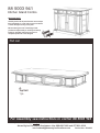
88 5003 941
Kitchen Island Combo
IMPORTANT NOTE
Carefully remove all the parts from the carton and put
them individually on a soft cloth to prevent scratches
or other damages occuring to the parts.
We have taken great care in the design of this
product and request that you carefully and strictly
follow our assembly instructions to ensure a
completed product as it was designed.
Tools required for assembly : Phillips screwdriver
Home Styles Consumer Assistance Line 888-680-7460 and 877-831-0319
A.
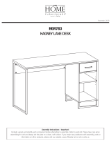
Top Unit
1 pc.
For assembly see instructions in carton 88 5003 943
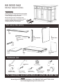
Part List
Revised date : 4Feb2013

Hardware List
Tools required for assembly : Phillips screwdriver
Home Styles Consumer Assistance Line 888-680-7460 and 877-831-0319
C.
Back Stretcher
2 pcs.
D.
Back Stretcher
1 pc.
E.
Middle Panel
1 pc.
F.
Rail
2 pcs.
G.
Shelf
4 pcs.
H.
Base
1 pc.
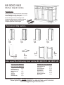
88 5003 942
Kitchen Island Combo
B.
Top
1 pc.
N.
Back Panel
2 pcs.
For assembly see instructions in carton 88 5003 943
Part List (in this carton)
Hex Wrench
1 pc.
Head Cap Bolt
18 pcs. (+1 extra)
Cam Lock
4 pcs.(+1 extra)
Cam Lock Screw
4 pcs.(+1 extra)
Machine Screw
4 pcs.
Drawer
Pull Handle
4 pcs.
Small
Hex Wrench
1 pc.
Adjustable Pin
32 pcs. (+1 extra)
Wood Screw
9 pcs. (+1 extra)
IMPORTANT NOTE
Carefully remove all the parts from the carton and put
them individually on a soft cloth to prevent scratches
or other damages occuring to the parts.
We have taken great care in the design of this
product and request that you carefully and strictly
follow our assembly instructions to ensure a
completed product as it was designed.

Part List (in this carton)
I.
Leg
1 pc.
J.
Leg
1 pc.
K.
Leg
1 pc.
L.
Leg
1 pc.
M.
Side Panel
2 pcs.
O.
Shelf
4 pcs.
P.
Door
1 pc.
Q.
Door
1 pc.
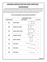
88 5003 943
Kitchen Island Combo
Tools Required For Assembly : Phillips screwdriver
Home Styles Consumer Assistance Line 888-680-7460 and 877-831-0319
Also need the following from carton 88 5003 941, 88 5003 942
Part List in carton 88 5003 941
Top Unit (A)
1 pc.
1 pc.
2 pcs.
1 pc.
1 pc.
2 pcs.
4 pcs.
1 pc.
2 pcs.
Part List in carton 88 5003 942
Top (B)
Back Stretcher (C)
Back Stretcher (D)
Middle Panel (E)
Rail (F)
Shelf (G)
Base (H)
Back Panel (N)
Hardware List in carton 88 5002 942
Hex Wrench
Small Hex Wrench
Cam Lock
Cam Lock Screw
Head Cap Bolt
Adjustable Pin
Machine Screw
Drawer Pull Handle
Wood Screw
1 pc.
1 pc.
5 pcs.
5 pcs.
19 pcs.
33 pcs.
4 pcs.
4 pcs.
10 pcs.
IMPORTANT NOTE
Carefully remove all the parts from the carton and put
them individually on a soft cloth to prevent scratches
or other damages occuring to the parts.
We have taken great care in the design of this
product and request that you carefully and strictly
follow our assembly instructions to ensure a
completed product as it was designed.

IMPORTANT
Do not tighten up all the screws until each part is properly assembled.
You should keep Hex Wrench in the safe place as you may need to tighten up the Head Cap Bolts in the future.
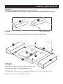
Assembly Instructions 2/4
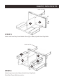
STEP 1
Put Cam Lock Screws into the pre-drilled holes of Leg (K),(L) and tighten.
Cam Lock Screw
K
L
Attach Back Stretcher (C) to Leg (K) using Cam Locks.
Attach Back Stretcher (D) to Back Stretcher (C).
Slide Back Panel (N) to unit, then attach Back Stretcher (C) to unit using Cam Locks.
Attach Leg (L) to the unit using Cam Locks.
STEP 2
K
L
N
N
C
D
C
Cam Lock

Assembly Instructions 3/4
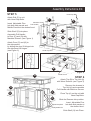
STEP 3
E
H
Attach unit from Step 2 and Middle Panel (E) to Base (H) with Head Cap Bolts.
STEP 4
Attach Leg (I) and (J) to Base (H) with Head Cap Bolts.
Slide Side Panels (M) into position.
J
I
M
M
Head Cap Bolt
Head Cap Bolt
H

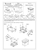
Assembly Instructions 4/4
STEP 5
Attach Rail (F) to unit
with Head Cap Bolts.
Insert Adjustable Pins
Into both side panels and
Middle Panels at the desired level.
Slide Shelf (G) into place.
Assemble Pull Handle
to Door (P) and (Q) with
Machine Screws. (see Figure 1)
Attach Door (P) and (Q) to
the side panels
by sliding the door lift hinges into
the side panel lift hinges.
(see Figure 2)
(Figure 1)
(Figure 2)
Attach Top (B) to Top Unit (A)
with Wood Screws. (see Figure 3)
Remove the drawers in
Top Unit (A) and assemble
Pull Handle with Machine Screws.
Place Top (A) on the unit with
Head Cap Bolts.
Slide the Drawers into position.
Insert Adjustable Pins
Into both side panels at
the desired level.
Slide Shelf (O) into Place.
STEP 6
A
O
O
O
O
G
G
G
G
F
F
P
Q
Head Cap Bolt
Head Cap Bolt
Pull Handle
Machine Screw
Head Cap Bolt
Adjustable Pin
(Figure 3)
A
B
Wood Screw
-
 1
1
-
 2
2
-
 3
3
-
 4
4
-
 5
5
-
 6
6


Home Styles 5003-948 Operating instructions
- Type
- Operating instructions
- This manual is also suitable for
Ask a question and I''ll find the answer in the document
Finding information in a document is now easier with AI
Related papers
-
Home Styles 6000-3158 Operating instructions
-
-
-
-
-
-
-
-
-
Other documents
-
 Riverside Furniture 27312 Assembly Instructions
-
Homestyles Pantry 5180-64 User manual
-
-
Homestyles 5003-94 Assembly Instructions
-
 Dorel Home 92655 Assembly Manual
-
-
-
 OSP Designs HGN783-FK Operating instructions
-
Symantec SERVICEDESK 7.0 MR2 Implementation Manual
-
Copernicus Be005 Assembly Instructions


