Page is loading ...

AntennaTek, Inc.
425 S. Bowen St., Suite 4
Longmont, CO 80501
(303)772-9591 FAX (303) 774-9533
www.antennatek.com
OWNER'S MANUAL
Form: manv1
THIS MANUAL CONTAINS
INSTRUCTIONS FOR: MOD 3000
- INSTALLATION
- TROUBLESHOOTING
- WARRANTY
SIGNAL COMMANDER II
®

2
SECTION I INSTALLATION INSTRUCTIONS
DISTRIBUTORS:
AUSTRALIA
Coast Connection
(02)9684-1434
CANADA
Danzy Distributors
(877)326-9962
NEW ZEALAND
RV Wholesale
64-7-825-2044
USA
Arrow (800) 228-1001
Coast (800) 495-5858
DTI (800)289-0919
Keller Marine (570)374-8169
Pantera Sales (800) 456-0123
AntennaTek (888) 349-8303
Power supplies should not be connected to existing
circuits with fans or motors as this may cause interfer-
ence to the television, damage the antenna amplifier,
and void the warranty.
Power supplies should be flush mounted in standard
electrical boxes. Assure that the 12 Volt DC source is
limited by a 7.5A fuse maximum.
TOOLS AND SUPPLIES
REQUIRED:
Mechanical Installation
- Electric Drill
- Drill bit: 1/16" Dia.
- Phillips screwdriver # 2
- Tape Measure
- 3/8" Wrench
- 5/32" Allen Wrench
Electrical Installation
- Multimeter
- Sabre Saw
- Crimping tool
Supplies
- Caulking Compound
- Electrical Tape
- Electrical Wire 14 AWG
- Electrical Box
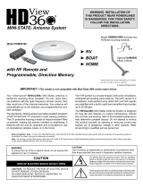
This manual contains information on the following Signal Commander® models; the model you have purchased
is clearly marked on the front of this manual.
MODEL 3000 Amplified Antenna, no Power Supply
MODEL 3500 Amplified, 2nd TV & Cable TV Ready
Vehicle Front
8 1/4"
WARNING !
Electricity Kills!
Power lines may be overhead.
Care must be taken when installing the
antenna.
MOD 3000 PARTS LIST
Qty. Description P/N
1 Omni Antenna Assembly 062200
9 # 6X3/4" PPH SS Screws 030212
2 Coaxial Cable Boots 040102
1 Roof Mounting Bracket 062206
1 Clamp bracket 062208
MOD 3500 PARTS LIST
Qty. Description P/N
1 Omni Antenna Assembly 062200
1 15' Coaxial Cable with boots 065580
1 6' Coaxial Cable 065543
10 #8x1" PPH Screws 065581
9 # 6X3/4" PPH SS Screws 030212
2 Coaxial Cable Boots 040102
1 Roof Mounting Bracket 062206
1 Clamp bracket 062208
1 Power Supply 065840
1. Installation Planning
Follow the instructions in this manual in conjuction
with the RV manufacture's recommendations to lo-
cate and install the Signal Commander Antenna and
power supply.
Locating the antenna close to the television receiver
and the 12 Volt DC power source will simplify the
installation. For best reception, stay as far as you can
from other roof mounted equipment to avoid any
interference.
2 1/4"
21 1/2"

2. Installation
WARNING!
Before drilling, care must be taken
not to damage any wiring that may be
located between the vehicle roof and
ceiling.
Step 1: Select the area where the antenna will be
installed. Drill one 1/2" OD hole through the roof
only, for the coaxial cable. Feed the end of the
coaxial cable through the hole on the mounting
bracket. Route the coaxial cable to the area where
the primary power supply will be installed.
Step 2: Seal the bottom of the mounting bracket
with non-hardening sealant. Center the mounting
bracket over the hole with the coaxial cable and
mount it on the roof with 10 #8x1" fully threaded
sheet metal screws. Seal the top of the screws.
Assure that the hole for the cable is facing the rear
of the vehicle.
Step 3: Mount the clamp bracket to the antenna
using 9 #6x3/4" sheet metal screws. Attach the
coaxial cable to the antenna and slide over the
coax cable boot.
Step 4: Place the antenna on top of the mounting
bracket, with the cable facing the rear of the
vehicle. Tighten the 2 #10 -24 screws using a 5/
32" Allen wrench and a 3/8" wrench. Slide the coax
cable boot over the hole on the mounting bracket.
Insert the # 8 x 3/4" self taping screw in the hole in
the front of the clamp bracket, using a #2 Phillips
screw driver, drive the screw through the mounting
bracket.
Step 5: The power supply is designed for installa-
tion in any standard electrical box. To mount the
Warning:
Use of this power supply
with any product other
than AntennaTek amplified
RV antenna could result in
fire or other damage.
Warning:
Do not connect high
current devices to 12 Volt
receptacle.
Maximum current rating
of this receptacle is: 7.5
Amps at 12 Volt DC.
power supply, cut a hole in the wall and install the
electrical box. Place the power supply switch in
the "OFF" position. Run two wires # 14 AWG or
heavier from a 12 Volt DC power source to the
rear of the power supply.
CAUTION: The red wire is positive (+)
The white wire is negative (-)
Assure that the 12 Volt DC power source current
is limited to 7.5A at 12-volt DC.
Crimp the insulated quick disconnects onto the
wires and push wires onto tabs on the circuit
board (see power supply illustration for correct
polarity). Place switch in the "ON" position and
notice the red LED illuminate. This indicates
correct polarity. Place switch in the "OFF" posi-
tion to avoid any short circuits while making
cable connections.
Step 6: Connect the coaxial cable from the
antenna to the connector marked "Antenna" on
the rear of the power supply.
Step 7: To connect the second power supply
available as an optional accessory, run two # 14
AWG or heavier wires from a 7.5A limited 12
Volt DC power source and connect to the rear of
the power supply. Insulate the DC connections
with wire nuts and insulating tape. Attach a coax
cable from the rear of the second power supply
to the connector marked 2nd TV in the rear of the
main power supply.
To Cable TV
To +12V DC
To Antenna
To 2nd TV
To GRND
3

LIMITED WARRANTY
AntennaTek, Inc. warrants this Signal Commander antenna, against any defects in material or workmanship for
one year from the date of purchase. AntennaTek, Inc., at its option, will repair or replace the defective product,
at no charge to you, provided that AntennaTek receives notice of a defect within one year from the original
purchase.
Promptly notify the seller, or alternately AntennaTek, of any claim hereunder. Provide proof of purchase to qualify
for credits under provisions of coverage. Obtain Authorization to Return from AntennaTek and return the product
to: AntennaTek, Inc., 425 S. Bowen St., Suite 4, Longmont, CO 80501, Phone 303-772-9591.
This warranty does not cover: any expenses for removal, travel, shipping, installation of the product, damage due
to misuse, improper installation, severe weather conditions, or other occurrences over which AntennaTek has no
control.
ALL OTHER WARRANTIES, WHETHER EXPRESS OR IMPLIED, INCLUDING OF MERCHANTABILITY OR
FITNESS FOR A PARTICULAR PURPOSE ARE LIMITED TO ONE YEAR FROM THE DATE OF PURCHASE.
LIABILITY FOR INDIRECT, SPECIAL OR CONSEQUENTIAL DAMAGES FOR ANY INCIDENTAL EXPENSES,
UNDER ANY AND ALL WARRANTIES IS EXCLUDED.
Some states do not allow limitation on how long an implied warranty lasts, or do not allow the exclusion or limitation
of incidental or consequential damages, so the above limitations may not apply to you.
This warranty gives you specific legal rights. You may also have other rights which vary from state to state.
Step 8: Place the power supply(s) inside the elec-
trical box(s) and mount flush with 2# 6x3/4" flat
head screws. Attach the coaxial cable(s) to the
front of the power supply(s) and connect to the
television set(s).
Step 9: Turn the switch ON on the main power supply.
Tune the TV receiver to the nearest TV station. Turn the
switch on the power supply OFF, the picture on TV
receiver should be degraded. This indicates that the
antenna is working properly.
SECTION III WARRANTY
SECTION II TROUBLESHOOTING
Cause
Switch off
DC power
Coax cable shorted
Television
Wiring
Antenna cables
Power supply
Vehicle location
Problem
LED on power supply does not
light up
Picture not clear
Note: Signals may be
interfered with if the an-
tenna is too close to ob-
structions such as build-
ings or trees.
Action
Turn switch ON
Check 12 V DC supply, & polarity
Replace coaxial cable
The power supply is equipped with a current
limiting device, which will shut off the power if
there is a short on the coaxial cable or the an-
tenna.
Tune in or change station
See installation steps 6-8
Coax cable going to antenna head should have
12V DC, between center conductor and outside
shield.
Switch ON (or OFF if you are too close to TV
transmitter)
Move vehicle
4
/