Page is loading ...

Model: PL21
For Technical Assistance (800) 638-3600 or visit www.magnadyne.com
INSTALLATION
MANUAL
Remote Mobile Security System

Step 1: Component Installation
Mounting the Control Module:
Find a suitable location to secure the alarm control module within the passenger’s compartment of the
vehicle. Never mount the alarm control module in the engine compartment or in the trunk. In addition, never
mount the alarm control module in the direct path of the heater. Secure the alarm control module by using
wire ties or drill two 1/8” holes and secure the module to the frame of the vehicle with the screws provided.
Installing Alarm Status LED:
The LED indicator provided utilizes a push in type mounting. Drill a 5/16” hole in the desired location,
feed the wires through the hole and push the LED into place. Run the wires to the location of the alarm
control module.
Mounting the Override/Valet Switch:
Mount this switch in a hidden but accessible location within reach of the driver of the vehicle. Drill a 1/4”
hole and use the nuts and washers provided to secure the switch. Run the wires from the switch to the
alarm control housing location.
2
Warning! Do not plug the 10-pin or 5-pin wire harness into the alarm control module before you
begin installing the alarm. The wire harnesses must be plugged into the alarm control module after all
connections are made. Failure to follow this procedure could cause some confusion with transmitter
operation and or alarm function operation.
Enclosed are the installation instructions for the PL21 alarm control module. Read through the instructions
to become familiar with the wiring and functions to insure a successful installation.
Step 2: Wire Connections
5-Pin Wire Harness Connections: (Power Supply Harness)
Red Wire: Connect the red wire to constant battery voltage. It is highly recommended to connect the red
wire directly to the (+) positive post of the vehicle battery for best performance of the alarm system.
Yellow Wire: Connect the yellow wire to a (+) power source that is switched On and Off by the
ignition key. This connection must be made to the “true ignition wire” directly from the ignition key
switch. When tested, the correct wire will indicate voltage when the ignition key is in the On and
Start positions. Connecting the yellow wire to any switched power source that does not stay On
when the key is in the start position will cause inconsistent operation of the security system.
Black Wire (Main Ground Input):
Connect the black wire directly to the frame of the vehicle. Use a
bolt and nut to secure the wire. Scrape away any grease or paint that might prevent a good connection.
10-Pin Wire Harness Connections: (Operations Harness)
The main wire harness contains 10 wires which all have a specific purpose. Follow the wiring
recommendations enclosed for each wire.
Gray Wire: The gray wire is a pulsed ground output designed to activate the vehicle’s existing car
horn system in place of or in addition to a siren sounding device. Connect the gray wire to the
negative trigger wire on the vehicle’s horn relay.
WARNING! Maximum output of this wire is 300mA to trigger the horn relay will require an
additional relay to increase current capabilities.

3
Step 2: Wire Connections (Continued)
10-Pin Wire Harness Connections: (Continued)
Blue Wire with White Stripe: No connection.
Brown Wire:
The brown wire is the positive siren output wire. Connect the brown wire from the
harness to the brown wire on the siren supplied. Ground the remaining black wire from the siren.
Blue Wire: The blue wire is a negative trigger input that can be used for existing or newly installed
grounding type hood/trunk/ hatch pin switches. The blue wire can also be used as an input for
additional ground output electronic sensors.
Green Wire: The green wire is the negative (-) door trigger input. If the vehicle you are working on
has a negative (-) triggered dome light system, connect the green wire to the common dome light
trigger wire. This wire is usually located at the driver’s side door jamb switch.
Violet Wire: The violet wire is the positive (+) door trigger input. If the vehicle you are working on
has a positive (+) triggered dome light system, connect the violet wire to the common dome light
trigger wire. This wire is usually located at the driver’s side door jamb switch.
Red Wire with White Stripe: The red/white wire is the output of the parking light relay. Connect
the red/white wire to the parking light trigger wire coming from the headlight switch. Do not
connect the red/white wire to a dashboard lighting wire. Connecting the red/white into dashboard
lighting can damage the dashboard lighting dimmer switch.
Pink Wire: The
pink wire is the input wire to the parking light relay. The connection of the pink wire
determines the output polarity of the parking light relay. If the parking light system you are connecting
to is positive activation, connect the pink wire to battery +12V DC. If the parking light system you are
connecting to is negative activation, connect the pink wire the the frame of the vehicl
e.
Step 3: Arm/Disarm Harness Wiring
3-Pin Harness with White Plug: (Arm/Disarm Harness)
Supplied with the PL21 is a 3 wire harness with a white 3-pin mini plug. This 3 wire harness gets connected to the
vehicle’s existing door lock switch wires and driver’s door lock motor unlock wire to arm and disarm the PL21.
Note: Their are two types of factory keyless entry systems available on 1994 and newer vehicles. Type 1
has the driver’s door unlock first feature. Older systems do not offer the driver’s door unlock first feature.
Follow the wiring information carefully.
Green Wire: Connect the green wire to any lock output wire controlled by the door lock control switch.
Blue Wire:
Connect the blue wire to the unlock from the driver’s door lock motor. DO NOT CONNECT
THE BLACK WIRE TO THE UNLOCK TRIGGER WIRE FROM THE DOOR LOCK CONTROL SWITCH.
White Wire: Connect the white wire to any unlock output wire controlled by the door lock control switch.
Note: If the keyless entry system you are connecting to does not have the unlock drivers door first
feature, connect the white wire to chassis ground. DO NOT LEAVE THIS WIRE DISCONNECTED.

4
Step 3: Arm/Disarm Harness Wiring (Continued)
Red Wire
Black 3-Pin Harness
(HAR-PL3)
Black Wire
Orange Wire
Driver's Door
Lock
Unlock
Factory Keyless
Module
(Typical)
Left Door
Lock/Unlock Switch
Lock
Unlock
Right Door
Lock/Unlock Switch
Left Door Jamb Right Door Jamb
Lock (+)
Unlock (+)
Lock (+)
Unlock (+)
Right Front Pass. Door
Left Rear Pass. Door
Lock (+)
Unlock (+)
Right Rear Pass. Door
Lock (+)
Unlock (+)
B
C
A
C
AA
C
A
A = Possible Connection Points for Red Wire
B = Connection Point for Black Wire
C = Possible Connection Points for Orange Wire
Inside Door Inside DoorInside Vehicle
B C A
2-Pin Black Wire Harness Connections: (Starter Disable Harness)
Locate the wire in the ignition switch harness that is used to send voltage to the starter relay. When tested,
the correct wire will show voltage when the ignition key is in the start position only. Cut the correct wire
and connect one of the black wires from the harness to each cut end. It is recommended to solder and
insulate these wires due to the high current they carry. Use the diagram enclosed, as reference for correct
wiring.
Step 4: Starter Disable Harness Wiring

5
Step 5: Auxiliary Interrupt Wiring
"ACC" "START"
"OFF" "ON"
Cut
Starter
Starter Disable Harness Connection (Applies to CA500 only)
2-Pin Plug from
Control Module
Step 4: Starter Disable Harness Wiring (Continued)
87
87a
86
85
30
87
87a
86
85
30
"ACC" "START"
CUT
"OFF" "ON"
Black Wire
Black Wire
Power Supply
to Fuel Pump
or
Power Supply to
Fuel Injectors
Red Wire
Orange
2-Pin
IInterrupt Two Circuits
Use ALA-RPS2
CUT
Black Wire
White Wire
White Wire
Power Supply
to ECM
or
Power Supply to
Ignition Coil
Interrupt
One Circuit
Use ALA-RPS
Interrupting Other Circuits
2-Pin Orange Socket: (Auxiliary Interrupt)
To interrupt an additional circuit(s) the alarm modules requires either the ALA-RPS, ALA-RPS2 or ALA-
RPS3 relay pack. Follow the wiring instructions below.
Step 6: Ignition Locking Wiring
3-Pin Black Socket: (Ignition Controlled Door Locking/Unlocking)
For ignition controlled door lock/unlock operation, follow the wiring diagram enclosed. The 3-pin
black connection harness is supplied but some locking systems will require an additional relay pack
(ALA-DL1).
Note: Some vehicle’s (Chrysler, Mazda, Ford) use one wire to lock and unlock the doors. To properly
interface with these one wire systems you must use part # ALA-DL1. We have developed a patented
plug-in fuse resistors to make the installation easier. Simply remove the fuses from ALA-DL1 module and
replace them with the correct resistor value fuses that match the vehicle’s door lock signal requirements.
Black Wire
Black Wire

Orange Wire
No Connection
Red
Black
Black
3
6
Step 6: Ignition Locking Wiring (Continued)
Black
3
Orange Wire
No Connection
Orange Wire - No Connection
Black
3
Black
3
Orange Wire
No Connection
Orange Wire - No Connection
Black
3
5 Wire Ground at Rest Door Locking Systems

7
Step 6: Ignition Locking Wiring (Continued)
One Wire Multiplexing Door Locking Systems
Valet Switch:
Plug the 2-pin blue connector on the valet switch wire harness into the mating blue connector on the
alarm control module.
Alarm Status LED Connection
LED Indicator:
Plug the 2-pin white connector on the LED wire harness into the mating white connector on the alarm
control module.
Step 7: Plug-In Components
2-Pin Blue Plug
2-Pin White Plug

8
Step 8: Programming the Alarm Control Module
The PL21 control module offers 6 programmable features: panic feature On/Off, chirp status and remote
start bypass On/Off, pathway illumination On/Off, automatic arming On/Off, ignition controlled locking
system On/Off, and single or double unlock pulse and timing duration. Follow the steps below to adjust the
features.
Plug In the Power
Harness
The horn/siren will start sounding, the
parking lights will flash and the LED
will begin flashing
OFF
ON
OFF
ON
Make Sure the Valet/
Override Switch is in the
“Off” Position
Step 1
Step 2
☛
ON
OFF
☛
☛
☛
☛
☛
☛
☛
☛
☛
O R
O R
Lock
Unlock
☛
Step 3
Turn On Ignition
Valet/Override Switch
Shock Sensor Port (Shock Sensor is Optional):
The white 4-pin plug on the control module will mate to the ALA90 or ALA95 dual-zone shock sensor.
If a different sensor device is desired, the HARPL4 accessory harness can be used to connect any
mechanical or electronic sensor to the PL21 control module (HARPL4 not supplied).
Dual Zone Electronic Sensor Plug: (Applies to PLUS-4000 Only)
Red Wire: +12 Volt Sensor Power Supply
Green Wire: Sensor Pre-Warning Output
Black Wire: Sensor Ground Supply
Blue Wire: Sensor Alarm Trigger Output
4 Pin White Plug
Single Zone Electronic Sensor Plug
Red Wire: +12 Volt Sensor Power Supply
Green Wire: No Connection
Black Wire: Sensor Ground Supply
Blue Wire: Sensor Alarm Trigger Input
4 Pin White Plug
Note: The black wire can be used to control other devices such as additional relays, window roll up control
modules or additional LED indicators. The black wire’s electrical capacity is 500mA. The black wire is
grounded when the alarm is armed only.
Step 7: Plug-In Components (Continued)

9
Step 8: Programming the Alarm Control Module (Continued)
Flip the Valet Switch
On/Off 4 Times
A. The horn/siren will chirp
1 long and 1
short
OFF
ON
OFF
ON
Depress the Factory Power Door “Unlock” Switch:
*1 Time = Panic Feature “On”
A. The siren will chirp once.
2 Times = Panic Feature “Off”
A. The siren will chirp two times. * Default Setting
Step 4A
☛
ON
OFF
☛
☛
☛
☛
☛
☛
☛
☛
☛
O R
O R
Lock
Unlock
☛
Step 4B
Panic Feature
Chirp Status Indication On/Off / Remote Start Bypass On/Off
Parking Lights Remain On After Disarm
Automatic Arming
Press the Factory Power Door “Unlock” Switch Until the
Desired Setting is Reached:
*1 Beep = Chirp Status Indicator is On / Remote Start
Bypass is Off
2 Beeps = Chirp Status Indicator is Off / Remote Start
Bypass is Off
3 Beeps = Chirp Status Indicator is On / Remote Start
Bypass is On
4 Beeps = Chirp Status Indicator is Off / Remote Start
Bypass is On
* Default Setting
Step 5A
Step 5B
Push the Valet Switch
6 Times for Red Button
12 Times for Black Button
(Represents 6 Times On/Off)
A. The siren will chirp 1 long and 3
short
Depress the Factory Power Door “Unlock” Switch:
1 Time = Parking Light Feature “On”
A. The siren will chirp once.
*2 Times = Parking Light Feature “Off”
A. The siren will chirp two times. * Default Setting
Step 6A
Step 6B
Push the Valet Switch
7 Times for Red Button
14 Times for Black Button
(Represents 7 Times On/Off)
A. The siren will chirp 1 long and 4
short
Depress the Factory Power Door “Unlock” Switch:
1 Time = Automatic Arming “On”
A. The siren will chirp once.
*2 Times = Automatic Arming “Off”
A. The siren will chirp two times. * Default Setting
Step 7A
Step 7B
Push the Valet Switch
5 Times for Red Button
10 Times for Black Button
(Represents 5 Times On/Off)
A. The siren will chirp 1 long and 2
short

10
Step 8: Programming the Alarm Control Module (Continued)
Step 9: Programmable Feature Testing
Remote Panic:
To test the remote panic feature follow the instructions below.
1. Ignition key must be Off.
2. Press the LOCK button on the factory transmitter 4 times.
3. The siren will begin to sound and the parking lights will begin to flash.
4. Press the UNLOCK button on the factory transmitter. The siren will stop sounding and the parking
lights will stop flashing.
Note: If the panic function is not turned off by the transmitter, the siren will continue to sound for 60
seconds and then turn off by itself.
C
hirp Delete:
The control module can be programmed in feature programming for no arm/disarm status chirps. The
four chirp tamper disarm warning indicator will always be on.
☛
ON
OFF
☛
☛
☛
☛
☛
☛
☛
☛
☛
O R
O R
Lock
Unlock
☛
Turn Off Ignition
A. 1 short and 1 long chirp
indicates you have exited
learning.
Step 10
Ignition Controlled Locking System
Push the Valet Switch
8 Times for Red Button
16 Times for Black Button
(Represents 8 Times On/Off)
A. The siren will chirp 1 long and 5
short
Depress the Factory Power Door “Unlock” Switch:
1 Time = Ignition Key “On”, Door Locking “On” +
Ignition Key “Off, Door Unlocking “Off”
A. The siren will chirp once.
2 Times = Ignition Key “On”, Door Locking “On” +
Ignition Key “Off, Door Unlocking “On”
A. The siren will chirp twice.
*3 Times = Ignition Key “On”, Door Locking “Off” +
Ignition Key “Off, Door Unlocking “Off”
A. The siren will chirp three times.
Step 8B
Door Lock Output Pulse and Output Duration
Push the Valet Switch
9 Times for Red Button
18 Times for Black Button
(Represents 9 Times On/Off)
A. The siren will chirp 1 long and 6
short
Press the Factory Power Door “Unlock” Switch until the
Desired Setting is Reached:
*1 Beep = .8 Sec. Door Lock/Unlock Outputs with
Single Unlock Pulse
2 Beeps = .8 Sec. Door Lock/Unlock Outputs with
Double Unlock Pulse
3 Beeps = .6 Sec. Door Lock/Unlock Outputs with
Single Unlock Pulse
4 Beeps = .6 Sec. Door Lock/Unlock Outputs with
Double Unlock Pulse
* Default Setting
Step 9A
Step 9B
Step 8A

11
Step 9: Programmable Feature Testing (Continued)
Pathway Illumination:
If the pathway illumination function has been programmed on the vehicle’s parking lights will illuminate
at the time the security system is disarmed by the remote transmitter. The parking lights will remain on
for 30 seconds after the security system is disarmed. Turning On the ignition key will turn off the parking
lights before 30 seconds.
Last Door Automatic Arming:
If the security system was programmed to automatically arm without using the transmitter, repeat the
following procedures to test and operate this feature:
1. Enter the vehicle and close all the entrances.
2. Set the ignition key switch to the On position and wait for 5 seconds.
3. Set the ignition key switch to the off position and exit the vehicle. Upon closing the door, you will
hear a beep from the horn/siren. The beep is an indicator that the automatic arming timer has started
counting. You will also notice that the LED indicator is flashing fast. This is also an indicator that the
automatic arming timer is counting down.
4. Within 30 seconds, the horn/siren will beep once again. This is an indication that the security system
is now in the armed mode. The LED will begin flashing at a normal rate.
Note: Once the ignition key switch is turned off, the automatic arming timer will start counting after the
last protected entrance is closed. Reopening any protected entrance within the 30 second time will stop the
counter and reset it. Closing the entrance will start the counter once again but you will not get a beep when
closing the door for the second time.
Ignition Key Controlled Door Locking/Unlocking:
If the ignition key lock/unlock function has been programmed on the doors will automatically become locked
3 seconds after the ignition key is set to the
O
n position or Unlocked after ignition key is turned off.
1. Enter the vehicle and close all protected entrances.
2. Turn the ignition key to the On position.
3. Within 3 seconds the door locks will become locked.
4. Turn off the ignition key. The door locks will become unlocked.
Notations About Ignition Controlled Locking
A. If a protected door is open, the ignition door locking function is disabled.
B. If the door locks are manually locked, the alarm system will still unlock them when the ignition key
is turned off.
C. The control module can be programmed to “not” unlock the doors when the ignition is turned off.
Remote Start Bypass:
If the Remote Start Bypass Feature has been programmed On, the trigger inputs for the hood, trunk,
shock sensor, starter disable and ignition will be turned off during the factory remote start procedure and
will continue to be disabled for 10 seconds after the factory remote start function is completed.
Fast Test:
1. Enter the vehicle and close all the entrances.
2. Press the LOCK button on the factory remote transmitter to arm the PL21.
3. Wait a few seconds then push the LOCK switch on the drivers door.
4. Insert the ignition key and start the vehicle. The vehicle should start and the PL21 should not trigger.
Note: If the dome light circuit is active during or after the factory remote start procedure, the PL21 will
become triggered through the door trigger input.
5. Shut off the engine and wait 10 seconds.
6. Attempt to restart the vehicle. The PL21 should trigger and the engine should not start (requires the
starter disable wires to be connected).

PL21-IM Rev. D 2-22-12
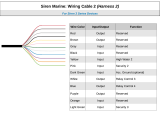
Wiring Diagram
Valet Switch
LED
Pink Wire Parking Lights Relay Input
Red/White Wire Parking Lights Relay Output
Violet Wire Positive Door Trigger Input
Green Wire Negative Door Trigger Input
Blue Wire Negative Pin Trigger Input
Brown Wire
Positive (+) Output for
an Optional Electronic Siren
Blue/White Wire No Connection
Gray Wire Horn (-) Pulsed Output
Starter Disable
Socket*
Power
Harness*
Driver's Door
Lock
Unlock
Factory Keyless
Module
(Typical)
Left Door
Lock/Unlock Switch
Lock
Unlock
Right Door
Lock/Unlock Switch
Left Door
Jamb
Right Door
Jamb
Lock (+)
Unlock (+)
Lock (+)
Unlock (+)
Right Front
Pass. Door
Left Rear
Pass. Door
Lock (+)
Unlock (+)
Right Rear
Pass. Door
Lock (+)
Unlock (+)
B
C
A
C
A
C
A
A
= Possible Connection Points for Green Wire
B = Connection Point for Blue Wire
C = Possible Connection Points for White Wire
Inside Door Inside DoorInside Vehicle
Shock Sensor
4-Pin Socket**** (White)
Arm/ Disarm
Harness Socket
(White)
Valet Switch Socket
(Blue)
Green Wire
White Wire
Blue Wire
Auxilliary Interrupt
Socket*** (Orange)
LED Socket
(White)
Ignition Locking Socket**
(Black 3-Pin)
Black Wire (Unlock)
(Optional)
Red Wire (Lock)
(Optional)
A
© Copyright 2006 Magnadyne Corporation
/