
HARDY
FLOOR SCALES
OPERATION AND INSTALLATION
MANUAL
Corporate Headquarters
9440 Carroll Park Drive
San Diego, CA 92121
Phone: (858) 278-2900
FAX: (858) 278-6700
Email: hardyinfo@hardysolutions.com
Web-Site: https://www.hardysolutions.com
Hardy Process Solutions Doc. Number: 0596-0335-01 Rev D
Copyright 2014-2020 Hardy Process Solutions.All Rights Reserved. Printed in the U.S.A.

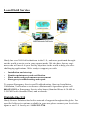
Local Field Service
Hardy has over 200 field technicians in the U.S., and more positioned through-
out the world to assist you in your support needs. We also have factory engi-
neers who will travel to your facility anywhere in the world to help you solve
challenging applications. We're ready to support you with:
•Installation and start-up
•Routine maintenance and certification
•Plant audits and performance measurement
•Emergency troubleshooting and repair
To request Emergency Service and Troubleshooting, Start-up, Installation,
Calibration, Verification or to discuss a Maintenance Agreement please call
800-821-5831 or Emergency Service after hours (Standard Hours 6:30 AM to
5:30 PM Pacific Standard Time) and weekends.
Outside the U.S
Hardy Process Solutions has built a network of support throughout the globe. For
specific field service options available in your area please contact your local sales
agent or our U.S. factory at +1 858-292-2710.

CAUTION:
UNPACK WITH CARE
WHEN UNPACKING, DO NOT DISCARD THE PACKING CASE OR ANY
PACKING MATERIAL, UNTIL THE CONTENTS OF THE PACKING CASE
ARE INSPECTED AND CAREFULLY COMPARED WITH THE SHIPPING
DOCUMENTS.
IF ANYTHING IS UNSATISFACTORY, PLEASE NOTIFY HARDY PRO-
CESS SOLUTIONS IMMEDIATELY BY CALLING, FAXING OR E-MAILING
US AT:
Hardy Service Center
Hardy Process Solutions
9440 Carroll Park Drive
San Diego, California 92121
Phone: (800) 821-5831
(858) 278-2900
FAX:(858) 278-6700
E-mail: [email protected]
Web Address: www.hardysolutions.com
TO RETURN DEFECTIVE OR DAMAGED PRODUCT(S) CALL HARDY
TECHNICAL SUPPORT FOR A HARDY SERVICE TICKET NUMBER
(HST#). YOUR COMPANY NAME, ADDRESS, TELEPHONE NUMBER,
SERIAL NUMBER OF THE UNIT AND A BRIEF DESCRIPTION OF THE
PROBLEM SHOULD BE READY WHEN CALLING. FOR ALL NON-WAR-
RANTY REPAIRS A PURCHASE ORDER OR CREDIT CARD IS ALSO
REQUIRED.
IN CASE OF DAMAGE DUE TO SHIPPING, NOTIFY THE DELIVERING
CARRIER IMMEDIATELY FOR AN INSPECTION.


Table of Contents
i
Table of Contents
Table of Contents - - - - - - - - - - - - - - - - - - - - - - - - - -i
INTRODUCTION - - - - - - - - - - - - - - - - - - - - - - - - - - - 1
SPECIFICATIONS - - - - - - - - - - - - - - - - - - - - - - - - - - 1
Platform Material - - - - - - - - - - - - - - - - - - - - - - - - - 1
Platform Height1
Rated Output - - - - - - - - - - - - - - - - - - - - - - - - - - - 1
Capacities - - - - - - - - - - - - - - - - - - - - - - - - - - - - 1
Excitation- - - - - - - - - - - - - - - - - - - - - - - - - - - - - 2
Load Points - - - - - - - - - - - - - - - - - - - - - - - - - - - 2
Total Error - - - - - - - - - - - - - - - - - - - - - - - - - - - - 2
Maximum Overload - - - - - - - - - - - - - - - - - - - - - - - - 2
End Loading - - - - - - - - - - - - - - - - - - - - - - - - - - - 2
HI 6011 Summing Box Power Rating - - - - - - - - - - - - - - - 2
Certifications - - - - - - - - - - - - - - - - - - - - - - - - - - - 2
Temperature Range - - - - - - - - - - - - - - - - - - - - - - - 3
Temperature Effect - - - - - - - - - - - - - - - - - - - - - - - - 3
Cable Length - - - - - - - - - - - - - - - - - - - - - - - - - - - 3
Materials of Construction - - - - - - - - - - - - - - - - - - - - -3
Steel - - - - - - - - - - - - - - - - - - - - - - - - - - - - -3
Paint - - - - - - - - - - - - - - - - - - - - - - - - - - - - -3
Foot Elastomer - - - - - - - - - - - - - - - - - - - - - - - - 3
Grade Level - - - - - - - - - - - - - - - - - - - - - - - - - - - 3
Accessories - - - - - - - - - - - - - - - - - - - - - - - - - - - 3
Anchor Bolt Holds - - - - - - - - - - - - - - - - - - - - - - 3
NEMA Rating- - - - - - - - - - - - - - - - - - - - - - - - - - - 3
Test Criteria - - - - - - - - - - - - - - - - - - - - - - - - - 4
UNPACKING - - - - - - - - - - - - - - - - - - - - - - - - - - - - - 4
COMPONENT DESCRIPTIONS - - - - - - - - - - - - - - - - - - - 5
SITE PREPARATION- - - - - - - - - - - - - - - - - - - - - - - - - 6
Precautions - - - - - - - - - - - - - - - - - - - - - - - - - - - 7
FLOOR SCALE INSTALLATION - - - - - - - - - - - - - - - - - - - 8
CALIBRATION - - - - - - - - - - - - - - - - - - - - - - - - - - - - 11

Hardy Floor Scales
ii
Pre-Calibration Procedures - - - - - - - - - - - - - - - - - - - -11
C2® Second Generation Calibration - - - - - - - - - - - - - - -12
Test Weight Calibration (Hard Cal) - - - - - - - - - - - - - - - -12
Requirements: - - - - - - - - - - - - - - - - - - - - - - - -12
Material Substitution: - - - - - - - - - - - - - - - - - - - - -13
SCALE VERIFICATION- - - - - - - - - - - - - - - - - - - - - - - -13
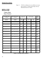
MODEL CODE BREAKDOWN - - - - - - - - - - - - - - - - - - - -14
Carbon Steel Deck, Painted- - - - - - - - - - - - - - - - - - - -14
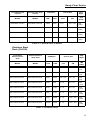
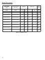
Stainless Steel Deck (304 SS) - - - - - - - - - - - - - - - - - - 15
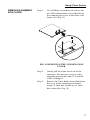
REMOVING SUMMING BOX COVER- - - - - - - - - - - - - - - - -17
Installing the Leveling Feet - - - - - - - - - - - - - - - - - - - -19
INSTALLING A LOAD SENSOR - - - - - - - - - - - - - - - - - - - 21
OPTIONAL PIT FRAMES - - - - - - - - - - - - - - - - - - - - - - -25
About Pit Frames - - - - - - - - - - - - - - - - - - - - - - - - -25
OPTIONAL PORTABILITY KIT - - - - - - - - - - - - - - - - - - - -30
OPTIONAL ACCESS RAMPS- - - - - - - - - - - - - - - - - - - - -30
Access Ramp Installation - - - - - - - - - - - - - - - - - - - - -30
OPTIONAL FOOT RETAINER - - - - - - - - - - - - - - - - - - - -33
Foot Retainer Plates Installation- - - - - - - - - - - - - - - - - -33
OPTIONAL BUMPER GUARDS- - - - - - - - - - - - - - - - - - - -34
Installing Bumper Guards - - - - - - - - - - - - - - - - - - - - -34
OPTIONAL INDICATOR COLUMN - - - - - - - - - - - - - - - - - -36
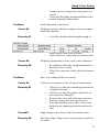
TROUBLESHOOTING - - - - - - - - - - - - - - - - - - - - - - - -36
Problem: - - - - - - - - - - - - - - - - - - - - - - - - - - -36
Cause #1: - - - - - - - - - - - - - - - - - - - - - - - - - -36
Cause #2: - - - - - - - - - - - - - - - - - - - - - - - - - -36
Cause #3: - - - - - - - - - - - - - - - - - - - - - - - - - -36
Remedies: - - - - - - - - - - - - - - - - - - - - - - - - - -36
Problem: - - - - - - - - - - - - - - - - - - - - - - - - - - -37
Cause #1: - - - - - - - - - - - - - - - - - - - - - - - - - -37
Remedy #1: - - - - - - - - - - - - - - - - - - - - - - - - -37
Cause #2: - - - - - - - - - - - - - - - - - - - - - - - - - -37

Table of Contents
iii
Remedy #2: - - - - - - - - - - - - - - - - - - - - - - - - - 37
Problem: - - - - - - - - - - - - - - - - - - - - - - - - - - - 37
Cause #1: - - - - - - - - - - - - - - - - - - - - - - - - - - 37
Remedy #1: - - - - - - - - - - - - - - - - - - - - - - - - - 37
Cause#2:- - - - - - - - - - - - - - - - - - - - - - - - - - - 37
Remedy #2: - - - - - - - - - - - - - - - - - - - - - - - - - 37
Cause #3: - - - - - - - - - - - - - - - - - - - - - - - - - - 38
Remedy #3: - - - - - - - - - - - - - - - - - - - - - - - - - 38
Cause #4: - - - - - - - - - - - - - - - - - - - - - - - - - - 38
Remedy #4: - - - - - - - - - - - - - - - - - - - - - - - - - 38
INSTRUMENTATION INTERFACE CABLE COLOR CODES - - - - - 38

Hardy Floor Scales
iv

Table of Illustrations
I
TABLE OF CONTENTS - - - - - - - - - - - - - - - - - - - - - - - I
INSTALLING THE CLOSED EYEBOLTS INTO THE TOP PLATE - - - 5
HI 6011 SUMMING JUNCTION CARD - - - - - - - - - - - - - - - - 6
WHEN DRIVING HEAVY EQUIPMENT ON AND OFF SCALE - - - - - 8
MAXIMUM HEIGHT - - - - - - - - - - - - - - - - - - - - - - - - - 8
SPIRIT LEVEL - - - - - - - - - - - - - - - - - - - - - - - - - - - -9
CHECKING PLATFORM LEVEL/SIDE TO SIDE- - - - - - - - - - - - 9
CHECKING PLATFORM LEVEL/CORNER TO CORNER - - - - - - - 10
CHECKING PLATFORM LEVEL/DIAGONALLY - - - - - - - - - - - -10
ADJUSTING THE FEET FOR LEVEL - - - - - - - - - - - - - - - - - 11
SCALE VERIFICATION/POSITION #3 - - - - - - - - - - - - - - - - 13
REMOVING THE SUMMING BOX COVER - - - - - - - - - - - - - - 17
REMOVING THE SUMMING BOX LID - - - - - - - - - - - - - - - - 18
A HARDY HI 6011 SUMMING BOX WITH THE LID REMOVED
(WITHOUT LOAD CELL CABLING) - - - - - - - - - - - - - - - - - - 18
INSERTING THE LEVELING FOOT INTO THE LOAD SENSOR- - - - 19
INSIDE VIEW- - - - - - - - - - - - - - - - - - - - - - - - - - - - - 20
OUTSIDE VIEW - - - - - - - - - - - - - - - - - - - - - - - - - - - 20
ALL FOUR FEET INSTALLED - - - - - - - - - - - - - - - - - - - - 21
SUMMING CARD- - - - - - - - - - - - - - - - - - - - - - - - - - - 21
CABLE GLAND- - - - - - - - - - - - - - - - - - - - - - - - - - - - 23
REMOVING LOAD SENSOR BOLTS AND FEET - - - - - - - - - - - 24
FOUNDATION FOR THE PIT FRAME - - - - - - - - - - - - - - - - 26
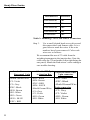
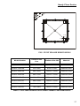
PIT FRAME DIMENSIONS - - - - - - - - - - - - - - - - - - - - - - 27
DRAIN INSTALLATION DIMENSIONS - - - - - - - - - - - - - - - - 28
EXCAVATED PIT AND SUPPORT FOR THE PIT FRAME- - - - - - - 29
RAMP WITH RETAINER PLATES - - - - - - - - - - - - - - - - - - 31
INSTALLING ANCHORS FOR RAMP - - - - - - - - - - - - - - - - - 32
FOOT RETAINER PLATES - - - - - - - - - - - - - - - - - - - - - 33
INSTALLATION - - - - - - - - - - - - - - - - - - - - - - - - - - - 33
BUMPER GUARD/GAP REQUIREMENT - - - - - - - - - - - - - - - 35
BUMPER GUARD/INSTALLATION - - - - - - - - - - - - - - - - - - 35

Hardy Floor Scales
II

Hardy Floor Scales
1
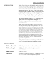
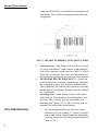
INTRODUCTION Hardy Floor Scales are designed for applications that
require a low profile weighing surface with high com-
mercial accuracy and reliability. These durable wash-
down scales can be used in hazardous areas with the
appropriate barriers. The Hardy Floor Scales can be
configured with a complete range of accessories. Rug-
ged Hardy Floor Scales are rated for 250,000 load
cycles under normal loading conditions.* They can be
sized or configured to fit any floor scale application.
*Contact Hardy for more information
The typical platform height is 3.375 inches (8.6 cm).
Each corner can be adjusted an additional .275”
(7mm) to compensate for a non-level floor or pit
mounting surface.
Hardy Floor Scales do not have bearings, levels or
moving parts that can be damaged or wear out. The
active elements of the floor scales are four precision
Hardy load sensors, mounted in all four corners of the
scale platform with an integrated HI 6011 junction
box. The unique Blind Hole Load Introduction tech-
nology allows the foot to move to compensate for
uneven floors. This ensures that the load forces are
always applied to the load sensor at precisely the
same point regardless of where the load is placed on
the scale. This ensures you will get accurate and
repeatable weighments.
Each platform load sensor is initially certified for use
in a C2® Second Generation Calibration system.
SPECIFICATIONS
Platform Material 0.25 inch painted carbon steel or stainless steel.
Platform Height 3.375 inches (8.6 cm) deck height adjustable
0.275” (7mm)
Rated Output 2.0mV/V ±0.1%
Capacities Available in eight sizes from 30 x 30 inch to 6 x 8 feet
in 1, 2.5, 5, and 10 thousand pound capacities

Hardy Floor Scales
2
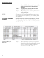
Excitation Recommended 5 Volts DC
• Maximum 5 Volts DC
WARNING FOR SCALES FITTED WITH AN INTEGRATED
TECHNICIAN SUMMING CARD, DO NOT
EXCEED 5 VDC EXCITATION. DOING SO MAY
CAUSE PROPERTY DAMAGE. DO NOT USE
WITH ANY INSTRUMENT WITH AN EXCI-
TATION VOLTAGE ABOVE 5 VDC.
Load Points HARDY ADVANTAGE® Load Sensors
• Factory Matched
• Stainless Steel
• True Hermetic Seal
• No Cornering
Total Error 0.03% of FS Output
Maximum
Overload
100% of the Rated Scale Capacity
End Loading 100% of the Rated Scale Capacity
HI 6011 Summing
Box Power Rating
5 VDC, Class 2 source, max. 50 mA
For Class I and II, Division 1 Hazardous (Classified)
Locations, and Class 1, Zone 0 and 2 Groups IIC,
Zone 20 and 22 Groups IIIC, power must be supplied
to the summing box through approved intrinsically
safe barriers per control drawing 0594-0010. (Avail-
able for download on the Hardy Floor Scales webpage
under Docs & Programs).
Certifications • UL, CUL, CE
• RoHS3 and REACH Compliant
•Hazardous Areas: Class I, Division 1,
Groups A, B, C, D, T4; Zone 0, Group IIC,
T4; Division 2, Groups A, B, C, D, T5
• Class II, Division 1, Groups E, F, G, T4;
Zone 20, Group IIIC; Division 2, Groups F,
G, T5
• Class III, Division 1, T4; Division 2, T5

Hardy Floor Scales
3
Temperature
Range
• Operating -40º to +80º Degrees C (-40º to
+176º F)
• Ambient -10 to +40 Degrees C (+14º to 104º
Degrees F)
Temperature
Effect
• On Output - 0.0011% of load/Deg. C
• On Zero - 0.0011% of FSO/Deg C
Cable Length 20 feet C2 Cable (6.096 meters)
NOTE: To purchase additional C2 Cable, contact our local
Hardy Process Solutions Representative or Hardy
Service Center.
Materials of
Construction
Steel • Carbon Steel: Type A36 carbon plate steel (slip
resistance - tread or smooth surface)
• Stainless Steel: Type 304 plate steel (slip resis-
tance - tread or smooth surface)
Paint Two-part UV resistant Polyurethane - 2 to 4 mil
top coat - Carbon Steel only.
Note: Stainless Steel scales are not painted)
Foot
Elastomer
• Natural Rubber (Standard)
Grade Level In operation, the scale must be firmly and adequately
supported at all four corners to accommodate the
maximum load in your application. The scale must be
installed to within 3º of level.
Accessories Ramps, Pit Frames, Bumper Guards, Lift Decks, Lift-
ing Eye Bolts, Bolt Down Plates
Anchor Bolt
Holds
1/2 inch bolts - 9/16” (.5625”) hole, 3.75 inches deep
5/8 inch bolts - 5/8” (.6250”) hole, 4.0 inches deep
•
NEMA Rating Summing Junction Box Enclosure - NEMA 4 Stain-
less Steel

Hardy Floor Scales
4
Test Criteria Must exclude at least 65 GPM of water from 1” inch
nozzle delivered from a distance not less than 10 ft for
5 minutes.
UNPACKING Hardy Floor Scales are shipped fully assembled and
wired. Inspect the container for any signs of damage
that might occur during shipment. Since almost all of
the Floor Scales are shipped F.O.B. factory, such dam-
age is normally the responsibility of the carrier and
should be reported to them.
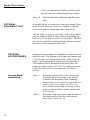
Step 1. Remove the banding straps and any ship-
ping restraints.
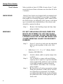
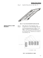
WARNING DO NOT USE HOOKS OR UNCLOSED EYE-
BOLTS OR ATTEMPT TO LIFT THE SCALE
MANUALLY. FAILURE TO USE THE PROPER
LIFTING TOOLS OR LIFTING METHODS CAN
CAUSE PERSONAL INJURY OR PROPERTY
DAMAGE.
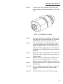
Step 2. Screw 2 closed eye bolts into the threaded
holes on the top plate of the scale. (See
Fig. 1)
• Mild Steel - 1/2 - 13 x 1.5” (Hardy Model
Number HIFSEB-PS)
Step 3. Attach a chain, cable or nylon strap to the
eyebolts.
Step 4. Use a forklift or crane with rated lifting
capacity that is equal to or greater than the
total weight of the platform scale to lift the
scale high enough to remove from the
crate bottom. See Tables 2 & 3 for ship-
ping weights.
Step 5. Be sure to use all safety precautions when
lifting the platform so that it does not fall
on equipment or personnel. It is highly
recommended that blocks be placed under
the platform before working near the plat-
form scale.

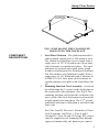
Closed Eye Bolts
for Lifting the
Platform Scale
Hardy Floor Scales
5
FIG. 1 INSTALLING THE CLOSED EYE-
BOLTS INTO THE TOP PLATE
COMPONENT
DESCRIPTIONS
1. Steel Plate Platform - The platform material is
either painted carbon steel or 304 stainless steel.
The carbon steel platform cover is made from a
single piece of 1/4" A36 carbon steel floor plate
(skid resistant) or smooth steel plate. The steel
platforms are primed and coated with a tough
weather resistant paint (See Paint Specifications).
The 304 stainless steel platform is made from a
single piece of 1/4" diamond tread (Conforms to
ASTM A793-85) floor plate (skid resistant) or
smooth stainless steel plate with a bead blast fin-
ish.
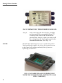
2. Summing Junction Card Assembly - Accessed
by unfastening the 2 screws on the deck plate on
the center side of the platform. (See Fig.2) The
summing junction card routes the excitation volt-
age to each of the four load sensors and sums the
weight signal back from them. The C2® second
generation electronic calibration is included with
your scale.
For Class I and II, Division 1 Hazardous (Classi-
fied) Locations, and Class 1, Zone 0 and 2
Groups IIC, Zone 20 and 22 Groups IIIC, power
must be supplied to the Summing Box through
approved intrinsically safe barriers per control

Hardy Floor Scales
6
drawing 0594-0010. (Available for download on
the Hardy Floor Scales webpage under Docs &
Programs).
FIG. 2 HI 6011 SUMMING JUNCTION CARD
3. Load Sensors - The Hardy series scales use four
(4) steel Advantage® load sensors with hermetic
seals. The output of each sensor is 2mV/V with 5
Volts DC excitation. For more specifications see
the electrical specification section of this manual.
4. INTEGRATED TECHNICIAN™ - A built-in
system diagnostics utility, continuously monitors
the weighing system for possible malfunctions.
This capability also allows the operator to rapidly
troubleshoot a weighing system from the control-
ler or indicator.
5. Leveling Feet - Each Hardy series scale comes
with four (4) 304 stainless steel adjustable level-
ing feet. The leveling feet are adjustable to a
maximum of 7mm (.275"). The leveling feet are
attached to each of the load sensors.
SITE PREPARATION • All mounting surfaces for the floor scale
should be level to within 3º, corner to corner,
end to end. Keep in mind that the adjustable
leveling feet have a maximum adjustment of
7mm (.275”).

Hardy Floor Scales
7
• For Class I and II, Division 1 Hazardous
(Classified) Locations, and Class 1, Zone 0
and 2 Groups IIC, Zone 20 and 22 Groups
IIIC, power must be supplied to the Sum-
ming Box through approved intrinsically
safe barriers per control drawing 0594-0010.
(Available for download on the Hardy Floor
Scales webpage under Docs & Programs).
• Before welding anything on the floor scale,
contact Hardy Process Solutions Service
Center for instructions and precautions.
• Proper drainage must be provided to prevent
the load sensors from standing in water.
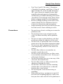
Precautions • Do not do any electric welding on or near the
platform scale.
• Do not drop items to be weighed on the
scale. Set them carefully on the platform
scale.
• Do not set items on the platform scale that
weigh more than the capacity of the scale.
• Do not store or operate the scale in environ-
ments out of the specified temperature range.
• Do not store other equipment on the scale
even temporarily when it is not used or in
storage.
• Do not allow debris to accumulate on,
around or under the scale.
• Do not set the scale in water or allow water
to accumulate around the scale. Always pro-
vide proper drainage.
• Do not let moisture get on or into any of the
electrical interconnections.
• Do not allow static or other electrical dis-
charges go through the scale.
• Do not leave the screws for the summing
junction box cover plate loose so that the
junction box is not sealed.
• Do not drop the scale when moving or
installing.
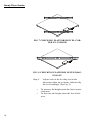
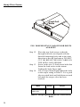
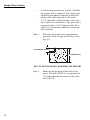
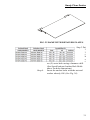
• When driving heavy equipment on and off
the scale for weighing purposes, make sure
that you drive onto and off of the platform in

Hardy Floor Scales
8
the direction indicated in Figure 3. Also See
Access Ramp Installation Section.
Load and unload
heavy equipment
in this direction only!
FIG. 3 DIRECTION WHEN DRIVING HEAVY
EQUIPMENT ON AND OFF THE SCALE
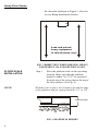
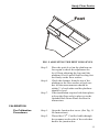
FLOOR SCALE
INSTALLATION
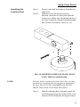
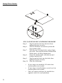
Step 1. Place the platform scale on the operating
location. Make sure that the platform
height is within 3 to 3.275" as measured
from the top of the cover plate to the top of
the floor surface. (See Fig. 4)
NOTE: With the scale in place, the clearance around the edge
of the platform and pit coping should be 1/4” to 3/8”.
3.275” (83.1mm)
FIG. 4 MAXIMUM HEIGHT

Hardy Floor Scales
9
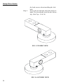
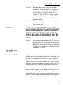
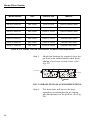
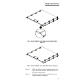
Step 2. Make sure that the platform mounting sur-
face is level to 1/8”.
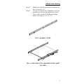
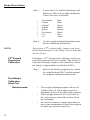
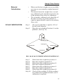
Step 3. Use a level (Spirit level, Bullseye level or
similiar) to check if the platform is level,
side to side, corner to corner and diago-
nally. (See Figs. 9, 10, 11, 12)
FIG. 5 SPIRIT LEVEL
FIG. 6 CHECKING PLATFORM LEVEL/SIDE
TO SIDE

Hardy Floor Scales
10
FIG. 7 CHECKING PLATFORM LEVEL/COR-
NER TO CORNER
FIG. 8 CHECKING PLATFORM LEVEL/DIAG-
ONALLY
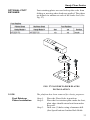
Step 4. Adjust each of the leveling feet in the
direction (either up or down), indicated by
the level readings. (See Fig. 9)
• To increase the height rotate the foot counter
clockwise.
• To decrease the height rotate the foot clock-
wise.
Page is loading ...
Page is loading ...
Page is loading ...
Page is loading ...
Page is loading ...
Page is loading ...
Page is loading ...
Page is loading ...
Page is loading ...
Page is loading ...
Page is loading ...
Page is loading ...
Page is loading ...
Page is loading ...
Page is loading ...
Page is loading ...
Page is loading ...
Page is loading ...
Page is loading ...
Page is loading ...
Page is loading ...
Page is loading ...
Page is loading ...
Page is loading ...
Page is loading ...
Page is loading ...
Page is loading ...
Page is loading ...
Page is loading ...
Page is loading ...
Page is loading ...
Page is loading ...
Page is loading ...
Page is loading ...
-
 1
1
-
 2
2
-
 3
3
-
 4
4
-
 5
5
-
 6
6
-
 7
7
-
 8
8
-
 9
9
-
 10
10
-
 11
11
-
 12
12
-
 13
13
-
 14
14
-
 15
15
-
 16
16
-
 17
17
-
 18
18
-
 19
19
-
 20
20
-
 21
21
-
 22
22
-
 23
23
-
 24
24
-
 25
25
-
 26
26
-
 27
27
-
 28
28
-
 29
29
-
 30
30
-
 31
31
-
 32
32
-
 33
33
-
 34
34
-
 35
35
-
 36
36
-
 37
37
-
 38
38
-
 39
39
-
 40
40
-
 41
41
-
 42
42
-
 43
43
-
 44
44
-
 45
45
-
 46
46
-
 47
47
-
 48
48
-
 49
49
-
 50
50
-
 51
51
-
 52
52
-
 53
53
-
 54
54


Ask a question and I''ll find the answer in the document
Finding information in a document is now easier with AI
Related papers

Other documents
-
uxcell A18112500UX0186 User manual
-
Hardy HILPRA User manual
-
-
-
Scaletron 3000-2000LB Operating instructions
-
Scaletron 4021™ Ultra Low Profile Scale Base User guide
-
-
-
-