
VARIABLE SPEED
TRACK SAW
Instruction Manual
IMPORTANT: Your new tool has been engineered and manufactured to WEN’s highest standards for dependability,
ease of operation, and operator safety. When properly cared for, this product will supply you years of rugged,
trouble-free performance. Pay close attention to the rules for safe operation, warnings, and cautions. If you use
your tool properly and for its intended purpose, you will enjoy years of safe, reliable service.
NEED HELP? CONTACT US!
Have product questions? Need technical support? Please feel free to contact us:
TECHSUPPOR[email protected]1-847-429-9263 (M-F 8AM-5PM CST)
For replacement parts and the most up-to-date instruction manuals, visit WENPRODUCTS.COM
MODEL CT1274

CONTENTS
WELCOME 3
Introduction ..................................................................................................... 3
Specifications ................................................................................................... 3
SAFETY 4
General Safety Rules ........................................................................................ 4
Track Saw Safety Warnings .............................................................................. 6
Electrical Information ....................................................................................... 9
BEFORE OPERATING 10
Unpacking & Packing List ...............................................................................10
Know Your Track Saw .................................................................................... 11
Assembly & Adjustments ............................................................................... 13
OPERATION & MAINTENANCE 19
Operation ....................................................................................................... 19
Troubleshooting Guide ....................................................................................23
Maintenance ....................................................................................................24
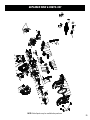
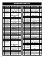
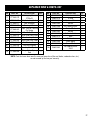
Exploded View & Parts List .............................................................................25
Warranty Statement ........................................................................................28
To purchase replacement parts, blades, and other accessories, visit WENPRODUCTS.COM
2
100-inch Track with Adapters (Model Number: CT9502)
110-inch Track with Adapters (Model Number: CT9110)
4-piece Track Adapter Set (Model Number: CT9011)
Pair of Track Clamps (Model Number: CT992F)

SPECIFICATIONS
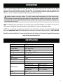
INTRODUCTION
Thanks for purchasing the WEN Track Saw. We know you are excited to put your tool to work, but first, please
take a moment to read through the manual. Safe operation of this tool requires that you read and understand this
operator’s manual and all the labels affixed to the tool. This manual provides information regarding potential safety
concerns, as well as helpful assembly and operating instructions for your tool.
NOTE: The following safety information is not meant to cover all possible conditions and situations that may occur.
WEN reserves the right to change this product and specifications at any time without prior notice.
At WEN, we are continuously improving our products. If you find that your tool does not exactly match this manual,
please visit wenproducts.com for the most up-to-date manual or contact our customer service at 1-847-429-9263.
Keep this manual available to all users during the entire life of the tool and review it frequently to maximize
safety for both yourself and others.
Indicates danger, warning, or caution. The safety symbols and the explanations with them deserve your
careful attention and understanding. Always follow the safety precautions to reduce the risk of fire, electric shock
or personal injury. However, please note that these instructions and warnings are not substitutes for proper ac-
cident prevention measures.
Model Number CT1274
Motor 120V, 60 Hz, 12A
No-Load Speed 2000 - 6000 RPM
Blade Part Number CT1274-060
Blade Size 7-1/4 in. (185mm) TCT
Arbor Size 5/8 in. (15.875mm)
Teeth 48T
Blade Thickness 1.0mm
Kerf 1.6mm
Blade Bevel 0° to 48°
Cutting Capacity
90° without track 2.64 in. (67mm)
45° without track 1.85 in. (47mm)
90° with track 2.44 in. (62mm)
45° with track 1.73 in. (44mm)
Weight 12 lbs
Product Dimensions 13 in. x 9-1/4 in. x 10 in.
3

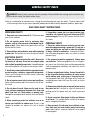
GENERAL SAFETY RULES
WORK AREA SAFETY
1. Keep work area clean and well lit. Cluttered or dark
areas invite accidents.
2. Do not operate power tools in explosive atmo-
spheres, such as in the presence of flammable liquids,
gases or dust. Power tools create sparks which may ig-
nite the dust or fumes.
3. Keep children and bystanders away while operating
a power tool. Distractions can cause you to lose control.
ELECTRICAL SAFETY
1. Power tool plugs must match the outlet. Never mod-
ify the plug in any way. Do not use any adapter plugs
with earthed (grounded) power tools. Unmodified plugs
and matching outlets will reduce risk of electric shock.
2. Avoid body contact with earthed or grounded surfac-
es such as pipes, radiators, ranges and refrigerators.
There is an increased risk of electric shock if your body
is earthed or grounded.
3. Do not expose power tools to rain or wet conditions.
Water entering a power tool will increase the risk of elec-
tric shock.
4. Do not abuse the cord. Never use the cord for car-
rying, pulling or unplugging the power tool. Keep cord
away from heat, oil, sharp edges or moving parts.
Damaged or entangled cords increase the risk of electric
shock.
5. When operating a power tool outdoors, use an ex-
tension cord suitable for outdoor use. Use of a cord
suitable for outdoor use reduces the risk of electric
shock.
6. If operating a power tool in a damp location is un-
avoidable, use a ground fault circuit interrupter (GFCI)
protected supply. Use of a GFCI reduces the risk of elec-
tric shock.
PERSONAL SAFETY
1. Stay alert, watch what you are doing and use com-
mon sense when operating a power tool. Do not use a
power tool while you are tired or under the influence
of drugs, alcohol or medication. A moment of inatten-
tion while operating power tools may result in serious
personal injury.
2. Use personal protective equipment. Always wear
eye protection. Protective equipment such as a respira-
tory mask, non-skid safety shoes and hearing protection
used for appropriate conditions will reduce the risk of
personal injury.
3. Prevent unintentional starting. Ensure the switch is
in the off-position before connecting to power source
and/or battery pack, picking up or carrying the tool.
Carrying power tools with your finger on the switch or
energizing power tools that have the switch on invites
accidents.
4. Remove any adjusting key or wrench before turning
the power tool on. A wrench or a key left attached to a
rotating part of the power tool may result in personal
injury.
5. Do not overreach. Keep proper footing and balance
at all times. This enables better control of the power
tool in unexpected situations.
6. Dress properly. Do not wear loose clothing or jew-
elry. Keep your hair and clothing away from moving
parts. Loose clothes, jewelry or long hair can be caught
in moving parts.
Safety is a combination of common sense, staying alert and knowing how your item works. The term “power tool”
in the warnings refers to your mains-operated (corded) power tool or battery-operated (cordless) power tool.
SAVE THESE SAFETY INSTRUCTIONS.
WARNING! Read all safety warnings and all instructions. Failure to follow the warnings and instructions may
result in electric shock, fire and/or serious injury.
4

GENERAL SAFETY RULES
7. If devices are provided for the connection of dust
extraction and collection facilities, ensure these are
connected and properly used. Use of dust collection
can reduce dust-related hazards.
POWER TOOL USE AND CARE
1. Do not force the power tool. Use the correct power
tool for your application. The correct power tool will
do the job better and safer at the rate for which it was
designed.
2. Do not use the power tool if the switch does not turn
it on and off. Any power tool that cannot be controlled
with the switch is dangerous and must be repaired.
3. Disconnect the plug from the power source and/or
the battery pack from the power tool before making
any adjustments, changing accessories, or storing
power tools. Such preventive safety measures reduce
the risk of starting the power tool accidentally.
4. Store idle power tools out of the reach of children
and do not allow persons unfamiliar with the power
tool or these instructions to operate the power tool.
Power tools are dangerous in the hands of untrained us-
ers.
5. Maintain power tools. Check for misalignment or
binding of moving parts, breakage of parts and any
other condition that may affect the power tool’s opera-
tion. If damaged, have the power tool repaired before
use. Many accidents are caused by poorly maintained
power tools.
6. Keep cutting tools sharp and clean. Properly main-
tained cutting tools with sharp cutting edges are less
likely to bind and are easier to control.
7. Use the power tool, accessories and tool bits, etc.
in accordance with these instructions, taking into ac-
count the working conditions and the work to be per-
formed. Use of the power tool for operations different
from those intended could result in a hazardous situa-
tion.
8. Use clamps to secure your workpiece to a stable
surface. Holding a workpiece by hand or using your
body to support it may lead to loss of control.
9. KEEP GUARDS IN PLACE and in working order.
SERVICE
1. Have your power tool serviced by a qualified repair
person using only identical replacement parts. This
will ensure that the safety of the power tool is main-
tained.
CALIFORNIA PROPOSITION 65 WARNING
Some dust created by power sanding, sawing, grinding,
drilling, and other construction activities may contain
chemicals, including lead, known to the State of Califor-
nia to cause cancer, birth defects, or other reproductive
harm. Wash hands after handling. Some examples of
these chemicals are:
• Lead from lead-based paints.
• Crystalline silica from bricks, cement, and other
masonry products.
• Arsenic and chromium from chemically treated
lumber.
Your risk from these exposures varies depending on
how often you do this type of work. To reduce your ex-
posure to these chemicals, work in a well-ventilated area
with approved safety equipment such as dust masks
specially designed to filter out microscopic particles.
Safety is a combination of common sense, staying alert and knowing how your item works. The term “power tool”
in the warnings refers to your mains-operated (corded) power tool or battery-operated (cordless) power tool.
SAVE THESE SAFETY INSTRUCTIONS.
WARNING! Read all safety warnings and all instructions. Failure to follow the warnings and instructions may
result in electric shock, fire and/or serious injury.
5

TRACK SAW SAFETY WARNINGS
TRACK SAW SAFETY
1. Always wear protective gloves when handling saw
blades.
2. Only use blades with correct size and type for both
your track saw and your workpiece.
• The rated diameter of the saw blade is
7-1/4 in.
with a
5/8-inch arbor.
• The no-load speed of this saw can be adjusted between
2000 and 6000 RPM. The maximum speed rating of your
saw blade should always be higher than 6000 RPM.
3. Never use damaged or deformed saw blades. Only use
sharp blades.
4. Install the saw blade in the correct orientation indi-
cated in the instructions.
5. Keep hands out of path of saw blade. Never use your
hands to remove sawdust, chips or workpiece near the
saw blade or the cutting path of the saw.
6. Never reach around saw blade or reach in back of the
saw blade.
7. Do not use blades made from high-speed steel, abra-
sive blades, metal-cutting blades or masonry-cutting
blades. The guards of this saw are not designed to pro-
tect against the failure of such blades.
8. The use of accessories or attachments not recom-
mended by the manufacturer may result in a risk of per-
sonal injury.
PERSONAL SAFETY
1. Operate in a well ventilated area. Keep the floor area
around the track saw level and free of slippery substanc-
es or other tripping hazards.
2. Wear ANSI-approved safety goggles to protect your
eyes from sparks and saw dust. Use hearing protection
to protect yourself from hearing loss.
3. People with pacemakers should consult their
physician(s) before use. Electromagnetic fields in close
proximity to pacemakers could cause pacemaker inter-
ference or pacemaker failure.
4. Wear work gloves when handling saw blades. DO NOT
wear gloves while operating the saw.
5. Sawdust is harmful to your health. Use NIOSH-ap-
proved dust masks or other respiratory protection dur-
ing operation and cleaning.
6. Always turn off and unplug the track saw before mak-
ing any adjustments or repair tasks. Never adjust the
track saw or the workpiece while the saw is running.
7. Never use damaged or incorrect blade flanges or bolt.
The blade flanges and bolt were specially designed for
your saw, for optimum performance and safety of opera-
tion.
8. Do not use to cut metal, logs, tree limbs, or uneven
lumber. Inspect the workpiece and remove all nails and
other embedded objects prior to starting work.
9. Wet lumber, green (unseasoned) lumber, and pres-
sure treated lumber all have an increased potential for
kickback and should only be cut with a blade specifically
designed for that lumber type. Wear a NIOSH-approved
respirator and have appropriate ventilation whenever
cutting pressure treated lumber.
PREPARING THE TRACK SAW
1. When transporting the track saw, carry it by either the
handle or the base. Never carry the device by its guards
or its accessories. Make sure that the blade is fully cov-
ered by the blade cover and not exposed.
2. Securely slide the track saw onto the track before op-
erating.
3. Examine the track saw for any damaged or missing
parts. Replace or repair damaged parts before operation.
Periodically check that all nuts, bolts and other fasteners
are properly tightened.
WARNING! Do not let comfort or familiarity with the product replace strict adherence to product safety rules.
Failure to follow the safety instructions may result in serious personal injury.
6

TRACK SAW SAFETY WARNINGS
WARNING! Do not let comfort or familiarity with the product replace strict adherence to product safety rules.
Failure to follow the safety instructions may result in serious personal injury.
7
SECURE YOUR WORKPIECE
1. To avoid blade binding or loss of control, always se-
cure the workpiece to a stable platform, ensuring that
body exposure is minimized. Use clamps to secure the
workpiece. Never perform any operation freehand.
2. Ensure that work is correctly supported. Large panels
may sag under their own weight and bind the saw blade.
Supports must be placed under the panel on both sides,
close to the line of cut and near the edge of the panel.
3. For accuracy of cut, and to avoid blade binding, al-
ways use a rip fence or straight edge guide.
4. Never hand-hold a workpiece that is too small to be
clamped, as it can be launched away and cause injury.
Use proper support and guides to secure the small
workpiece.
DURING CUTTING OPERATIONS
1. Always stand to one side when operating the saw.
Never have any part of the body in line with the path of
the saw. Never hold a workpiece in your hand or across
your legs while cutting.
2. Ensure hands are away from the cutting area and
blade. Keep one hand on the rear handle, and the other
on the front grip. If both hands are holding the tool they
cannot be cut by the blade.
3. Feed work into the blade against the direction of rota-
tion of the blade only.
4. If you are interrupted when operating the saw, com-
plete the process and switch the saw off before looking
up.
5. Power tools must always be held by the insulated
gripping surfaces when performing an operation, ensur-
ing protection if the cutting tool makes contact with its
own cord or hidden wiring. Contact with a ‘live’ wire will
make exposed metal parts of the power tool ‘live’ and
shock the operator if the insulated gripping surfaces are
not used.
6. Do not use the track saw unless all guards are in
place. Do not operate with any guard disabled, damaged,
or removed. Moving guards must move freely and close
instantly.
7. Turn on the track saw and let it reach full speed, then
slowly slide the saw into the workpiece. This will help
produce safer and cleaner cuts.
8. Always push the saw blade forwards and away from
you. Do not pull the saw towards you, or move the saw
backwards while cutting. Do not apply any sideways or
twisting force to the blade while cutting.
9. Never cut more than one piece at a time. Do not stack
workpieces together. Do not attempt to cut material
thicker than specified on page 2 of this manual. Adjust
the cutting depth to the thickness of the workpiece (less
than a full tooth of the blade should be visible below the
workpiece).
10. If a cut does not extend to the edge of the workpiece,
or if the blade binds in the cut, allow the blade to come
to a complete stop and lift the saw out of the workpiece.
11. Turn off tool and wait for saw blade to stop before
moving workpiece or changing settings. Do not slow or
stop a blade with a piece of wood. Let the blade come
to rest naturally. Do not attempt to free a jammed blade
while the machine is still running and connected to pow-
er.
12. Always raise the blade to be covered by the blade
guard after use.

8
TRACK SAW SAFETY WARNINGS
REDUCING KICKBACK
Kickback is a sudden reaction to a pinched, bound or
misaligned saw blade, causing an uncontrolled saw to
lift up and out of the workpiece toward the operator, in-
creasing the chances of serious personal injury. Do not
rely on the safety devices built into the saw. Track saw
users should take as many precautions as possible to
minimize on-site accidents. Kickback is the result of tool
misuse and/or incorrect operating procedures. These
conditions can be minimized with the following steps:
1. Maintain a firm grip with both hands on the saw and
position your arms to resist kickback forces. Position
your body to either side of the blade but not in line with
the blade. Kickback could cause the saw to jump back-
wards, however, if proper precautions are taken, kick-
back forces can be controlled by the operator. Do not let
go of the track saw.
2. If the blade is binding, or interrupting a cut for any
reason, release the trigger and hold the saw motionless
in the workpiece until the blade comes to a complete
stop. Never attempt to remove the saw from the work
or pull the saw backward while the blade is in motion.
Investigate and take corrective action to eliminate the
cause of blade binding.
3. When restarting a saw within an incomplete cut, cen-
ter the saw blade in the kerf and check that the saw teeth
are not engaged into the material (a binding saw blade
may ‘propel upwards’ or kickback from the workpiece as
the tool is restarted).
4. A large workpiece should be supported close to the
line of the cut, and at the edge of the panel, to prevent
sagging. This will minimize the risk of blade pinching
and kickback.
5. Do not use dull or damaged blades. Unsharpened or
improperly set blades produce narrow kerf causing ex-
cessive friction, blade binding, and kickback.
6. Blade depth and bevel adjusting locking levers must
be tight and secure before making a cut. If blade ad-
justment shifts while cutting, it may cause binding and
kickback.
7. Use extra caution when making a ‘plunge cut’ into ex-
isting walls or other blind areas. The protruding blade
may cut objects causing kickback.
8. Do not use abrasive wheels, doing so will void the
warranty.
WARNING! Do not let comfort or familiarity with the product replace strict adherence to product safety rules.
Failure to follow the safety instructions may result in serious personal injury.

ELECTRICAL INFORMATION
AMPERAGE REQUIRED GAUGE FOR EXTENSION CORDS
25 ft. 50 ft. 100 ft. 150 ft.
12A 14 gauge 12 gauge Not Recommended Not Recommended
IMPORTANT: Servicing a double-insulated product requires extreme care and knowledge of the system, and
should be done only by qualified service personnel using identical replacement parts. Always use original factory
replacement parts when servicing.
1. Polarized Plugs. To reduce the risk of electric shock, this equipment has a polarized plug (one blade is wider than
the other). This plug will fit in a polarized outlet only one way. If the plug does not fit fully in the outlet, reverse the
plug. If it still does not fit, contact a qualified electrician to install a proper outlet. Do not modify the machine plug
or the extension cord in any way.
2. Ground fault circuit interrupter protection (GFCI) should be provided on the circuit or outlet used for this power
tool to reduce the risk of electric shock.
3. Service and repair. To avoid danger, electrical appliances must only be repaired by a qualified service technician
using original replacement parts.
GUIDELINES AND RECOMMENDATIONS FOR EXTENSION CORDS
When using an extension cord, be sure to use one heavy enough to carry the current your product will draw. An
undersized cord will cause a drop in line voltage, resulting in loss of power and overheating. The table below shows
the correct size to be used according to cord length and ampere rating. When in doubt, use a heavier cord. The
smaller the gauge number, the heavier the cord.
DOUBLE-INSULATED TOOLS
The tool’s electrical system is double-insulated where two systems of insulation are provided. This
eliminates the need for the usual three-wire grounded power cord. Double-insulated tools do not need
to be grounded, nor should a means for grounding be added to the product. All exposed metal parts are
isolated from the internal metal motor components with protecting insulation.
1. Examine extension cord before use. Make sure your extension cord is properly wired and in good condition.
Always replace a damaged extension cord or have it repaired by a qualified person before using it.
2. Do not abuse extension cord. Do not pull on cord to disconnect from receptacle; always disconnect by pulling on
plug. Disconnect the extension cord from the receptacle before disconnecting the product from the extension cord.
Protect your extension cords from sharp objects, excessive heat and damp/wet areas.
3. Use a separate electrical circuit for your tool. This circuit must not be less than a 12-gauge wire and should be
protected with a 15A time-delayed fuse. Before connecting the motor to the power line, make sure the switch is in
the OFF position and the electric current is rated the same as the current stamped on the motor nameplate. Running
at a lower voltage will damage the motor.
9

10
UNPACKING
Thanks for taking the plunge and buying this saw. With the help of a friend or trustworthy foe, carefully remove the
track saw from the packaging. Make sure to take out all contents and accessories. Do not discard the packaging
until everything is removed. Check the packing list below to make sure you have all of the parts and accessories. If
any part is missing or broken, please contact our customer service at 1-847-429-9263, M - F, 8 - 5 CST, or
UNPACKING & PACKING LIST
PACKING LIST
The items listed below are not included, but are commonly bought with the this saw and made specifically for this
track saw (Model Number: CT1274). These items can be purchased at wenproducts.com; to easily find the items on
our website, search their model numbers:
• 100-Inch Track with Adapters (Model CT9502)
• 110-Inch Track with Adapters (Model CT9110)
• 4-Piece Track Adapter Set (Model CT9011)
• Pair of Track Clamps (Model CT992F)
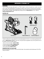
TRANSPORTING THE TRACK SAW
Before transporting your track saw, make sure that the blade is fully retracted inside the blade guard. Only lift the
saw by the handles.
Track Saw (1)
Carbon Brushes (2)
5mm Hex Wrench (1) Dust Port Adapter (1)

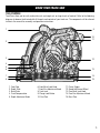
TOOL PURPOSE
Track Saws allow you to easily make miter cuts and rough cuts on large sheets of material. Refer to the following
diagrams to become familiarized with all the parts and controls of your track saw. The components will be referred
to later in the manual for assembly and operation instructions.
KNOW YOUR TRACK SAW
11
1
2
3
6
4
5
7
8
9
11
12
13
14
1. Front Grip
2. Depth Scale
3. Bevel Scale
4. Track Compensation
5. Depth Adjustment Knob
6. Front Bevel Lock Knob
7. Front Fine Adjustment Knob
8. Track Lock
9. Plunge Lock Button
10. Dust Port
11. Power Trigger
12. Speed Adjustment Wheel
13. Rear Bevel Lock Knob
14. Rear Fine Adjustment Knob
15. Base Plate
15
10

12
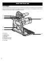
TOOL PURPOSE
Track Saws allow you to easily make miter cuts and rough cuts on large sheets of material. Refer to the following
diagrams to become familiarized with all the parts and controls of your track saw. The components will be referred
to later in the manual for assembly and operation instructions.
KNOW YOUR TRACK SAW
16. Dust Port
17. Spindle Lock
18. Mode Selector
19. Saw Blade
20. Slot for Parallel Guide
21. Carbon Brush Cover
22. Track Slot
16
17
18
20
21
22
19

ASSEMBLY & ADJUSTMENTS
WARNING! Do not plug in or turn on the tool until it is fully assembled according to the instructions. Read
through and become familiarized with the following procedures of handling and adjusting your track saw. Failure
to follow the safety instructions may result in serious personal injury.
13
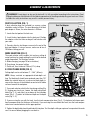
DUST COLLECTION (FIG. 1)
A dust collection bag (not included) or vacuum system
should be used at all times. The inner diameter of the dust
port adapter is 35mm; the outer diameter is 39.5mm.
1. Locate the dust port on the track saw.
2. Insert the dust port adapter into the dust port. Position
the adapter so the dust hose or bag will not interfere with
your work.
3. Securely attach a dust bag or vacuum to the end of the
dust port adapter. If using a vacuum, make sure to turn it
ON before starting your cut.
MODE SELECTION (FIG. 2)
The mode selector switch enables fast and easy setting of
major functions by simply rotating the switch to the desired
mode of operation. The functions include:
A. Blade changing (see page 18 for instructions)
B. Free plunge, for general cutting
C. Scribe cut, for a scribe cut 2.5mm (0.1 in) deep
B. FREE PLUNGE MODE (FIG. 3)
Cutting depth can be set between 0” -
2.64” (67mm)
.
NOTE: Always maintain an appropriate blade-depth set-
ting. The blade teeth should never protrude more than 1/8”
below the material being cut, as excessive blade depth in-
creases the chances of saw kickback or contact with hidden
surfaces beneath the workpiece.
1. Turn mode selector switch to the free-plunge setting (Fig.
2). Unplug your track saw. Loosen the depth adjustment
knob (Fig. 3 - 4) and slide it up or down so the indication
arrow (Fig. 3 - 2) points to the desired depth on the depth
scale (Fig. 3 - 3).
2. If you are using the saw with the track, turn the track compensation lever (Fig. 3 - 2) clockwise to the lower posi-
tion to compensate for the thickness of the track. If you are using the saw without the track, turn the track compen-
sation lever counterclockwise to the upper position.
3. Tighten the depth adjustment knob to lock it into place. Test the depth setting on a piece of scrap material to make
sure it is correct before plugging the saw back in.
Fig. 1
Fig. 3
Blade
Change
Free
Plunge
Scribe
Cut
Fig. 2
ModeMode
SelectorSelector
Mode
Selector
Dust Port
Dust Port Adaptor
1
2
3
4

14
ASSEMBLY & ADJUSTMENTS
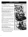
C. SCRIBE CUTS
1. Turn the mode selector switch to the scribe cut func-
tion; see “Mode Selection” on page 13.
2. Press the plunge lock button (Fig. 4) and plunge the
saw downwards. It will stop at a 2.5mm (0.1 in) depth
of cut.
NOTE: An initial scribe cut (before additional cuts) helps
prevent friction on the blade, particularly when deep
plunge cuts are required. It is also helpful for initial cuts
on veneered or melamine laminates.
ADJUSTING THE BEVEL ANGLE (FIGS. 5 & 6)
The saw can be beveled between 0° - 45°.
1. Unplug your track saw. Loosen both bevel lock knobs
(Fig. 5). Bevel the saw so that the indication arrow is
pointing to the desired angle on the bevel scale.
2. Tighten both bevel lock knobs to lock the bevel angle
into place.
3. Make a test cut in a piece of scrap material. Measure
the angle of the cut to confirm that the bevel angle is
properly set. If necessary, re-adjust the bevel angle be-
fore cutting the actual workpiece.
NOTE: The bevel indication arrow should be properly
adjusted at the factory. If you find that it is inaccurate,
adjust it using the steps below.
1. Make a test cut. Measure the bevel angle.
2. Loosen the Phillips-head screw on the bevel indica-
tion arrow. Adjust the arrow so that it points to the angle
of the cut. Tighten the screw.
LINE-OF-CUT INDICATORS (FIG. 7)
Two line-of-cut indicators can be found on the base of
the track saw. These notches help you to align your cuts.
1. Mark your cut on your workpiece. Locate the line-of-
cut indicators on the front and back of the base plate.
Instructions continue on the next page.
Fig. 4
Fig. 5
Fig. 6
Plunge LockPlunge Lock
ButtonButton
Plunge Lock
Button
BevelBevel
ScaleScale
Bevel
Scale
Front BevelFront Bevel
Lock KnobLock Knob
Front Bevel
Lock Knob
Indication Indication
ArrowArrow
Indication
Arrow

15
ASSEMBLY & ADJUSTMENTS
2. Follow step “2.1” if you are using the track, follow
step “2.2” if you are not using the track.
2.1) When using the saw with the track, always align
position A (the “0” mark on the base plate) with your
marked cutting line.
2.2) When using the saw without the track, align posi-
tion A (the “0” mark on the base plate) with your marked
cutting line for straight cuts. Align position B (the “45”
mark on the base plate) with your marked cutting line for
45° bevel cuts.
NOTE: Since blade thicknesses vary, it is necessary to
make test cuts along a guide line on a piece of scrap ma-
terial to determine the proper alignment of the guideline
within the notch. This will help to obtain an accurate cut
with blades of various thicknesses.
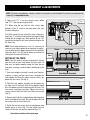
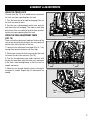
SETTING UP THE TRACK
NOTE: You will need to remove the protective sleeves
from the ends of each track before using the track. To
help your saw glide smoothly along the track, do not
allow dust, shavings, or other debris to build up on the
track.
1. Each track adapter assembly is made up of 6 pieces:
a spacer, a sleeve, and four hex screws. Assemble the
track adapter by fitting the spacer into the sleeve, op-
posite the hex screws. See Fig. 8.
2. Slide the track adapter assembly into the groove on
the front face of the track. Half of the adapter should
be in the groove and half should hang off the track. The
hex screws should be accessible. Tighten the two hex
screws that are within the track with a 3mm hex wrench
(Fig. 9).
3. Repeat step 2 with the second adapter and the groove
on the underside of the track. Be sure to tighten the two
hex screws that are within the track.
4. Guide the two free halves of the track adapters onto
another piece of track (Fig. 10) and tighten the hex
screws on the face side and the underside (Fig. 11).
Instructions continue on the next page.
NOTE: The track, track adapters, clamps, and 3mm hex wrench are not included. These items can be purchased
separately at wenproducts.com.
Fig. 7
Fig. 8
Fig. 9
AAA
BBB
Track
Hex ScrewsSleeve
Spacer
Track Adapter Assembly

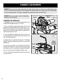
ASSEMBLY & ADJUSTMENTS
5. Align the track along the workpiece, the right-hand
(flat) side of the track is where the actual cut will occur.
Clamp down the track to the work surface so the track
is secure.
6. Place the saw onto the track. Make sure the blade will
contact the workpiece as intended.
7. Use the fine-adjustment cams to line up the track’s
edge and the saw’s cutting path with one another. Refer
to page 17.
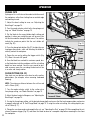
CUTTING THE RUBBER STRIP
The rubber strip running along the edge of the track
comes in its uncut original state. This rubber strip has
two main applications. Firstly, it acts as a straightedge,
allowing users to visualize the exact location of the cut.
Secondly, it helps prevent dust from flying up during
sawing operations. Because of the precision required for
these two applications, users must cut this rubber strip
themselves before using the track saw on any work-
pieces. This ensures every track perfectly complements
a particular track saw.
1. Turn the mode selector switch to the free-plunge set-
ting, see “Mode Selection” on page 13. Set the depth
stop to 1/2”, limiting the blade’s maximum cutting depth.
2. Clamp the track into place so that you can cut the full
length of the track in one go.
3. Position the saw onto the end of the track with the
back two-thirds of the saw hanging off. The goal should
be to maximize the amount of the saw’s base that is on
the track while still being able to plunge the full 1/2”
downwards without yet contacting the rubber strip with
the blade (Fig. 12).
4. Start the saw and then plunge downwards, making
sure to not yet contact the rubber strip. Once the saw
has reached full speed and is plunged the full 1/2”, prog-
ress forward along the track so that the blade makes
contact with the rubber strip.
5. Cut the rubber strip along the full length of the track.
Once you have made it all the way down the track, the
strip should be precision-cut to meet the specifications
of your particular track saw.
16
1/3 of
Track
Base
Blade
Track
with Strip
1/2"
Fig. 10
Fig. 11
Fig. 12

17
ASSEMBLY & ADJUSTMENTS
USING THE TRACK LOCK
The track lock (Fig. 13) is an added measure to prevent
the track saw from separating from the track.
1. Push the track lock to the right to disengage, then set
the track saw onto the track.
2. Once the saw is sitting properly on the track, push the
track lock to the left to engage. This hooks a small plate
on the base of the saw under the lip of the track, prevent-
ing the saw from separating from the track.
USING THE FINE-ADJUSTMENT CAMS
(FIG. 14)
There are two fine-adjustment knobs on the base of the
saw to help eliminate play between the track guide rail
and the track slot on the base of the saw.
1. Loosen the fine-adjustment cam knobs (Fig. 14 - 1) by
turning them counter-clockwise until they stop.
2. Set the track saw on the track, ensuring that the track
rail enters the slot in the saw base (Fig. 15).
3. Turn the fine-adjustment cam knobs clockwise until
the play has been taken out of the track saw’s movement
in the track. Avoid overtightening so that the saw has
smooth movement.
4. Move the saw forward along the track, ensuring its
movement is smooth. Repeat step 3 if adjustments are
needed.
Fig. 13
Fig. 14
Fig. 15
TrackTrack
LockLock
Track
Lock
11
TrackTrack
SlotSlot
Track
Slot

ASSEMBLY & ADJUSTMENTS
CHANGING THE SAW BLADE
1. Unplug your track saw. Turn the mode selector switch
to the blade changing setting (p. 13, Fig. 2).
2. Press and hold the plunge lock button (Fig. 16) and
plunge the saw downwards until the arbor screw is vis-
ible in the blade guard window. Release the plunge lock
button; the saw should now be locked in place and un-
able to be plunged or raised.
3. Press and hold the spindle lock (Fig. 16), then use
the included 5mm hex wrench to loosen the arbor screw
(turn it counterclockwise).
4. Remove the screw and outer flange (Fig. 17). Slide the
blade off the arbor and downwards until it is clear of the
blade guard.
5. Install the new blade on the arbor. Ensure that the
blade rotation direction is correct. Install the outer flange
and arbor screw. Press and hold the spindle lock button,
then use the hex wrench to tighten the arbor screw.
6. Press and hold the plunge lock button to release the
saw, then raise it.
DANGER! Never try to use a blade larger than the stated capacity of the saw. Do not use a blade thicker than
1.9mm. It will prevent the blade screw from properly securing the blade on the arbor. Install the suitable blade
for your cutting operation. See page 2 and page 6 for specifications and saw blade safety.
DANGER! Always wear gloves while handling blades
to prevent cuts and injuries.
18
Plunge LockPlunge Lock
ButtonButton
Plunge Lock
Button
SpindleSpindle
LockLock
Spindle
Lock
Screw
Outer
Flange
Blade
Rotation
Direction
Fig. 16
Fig. 17

OPERATION
WARNING! Do not plug in or turn on the tool until it is fully assembled according to the instructions. Read
through and become familiarized with the following procedures of handling and adjusting your track saw. Failure
to follow the safety instructions may result in serious personal injury.
WARNING! Always let the blade reach full speed before guiding the saw into the workpiece. The blade com-
ing into contact with the workpiece before reaching full speed, could cause your saw to KICKBACK towards you
resulting in serious personal injury.
WARNING! If, while operating the saw, the cord hangs up on the workpiece or some other object during a
cut, release the switch trigger immediately. Unplug the saw and reposition the cord to prevent it from hanging
up again.
STARTING/STOPPING THE SAW (FIG. 18)
1. Plug in the tool.
2. To start the saw, press and hold the plunge lock but-
ton, then pull the power trigger. Once the saw reaches
maximum speed, plunge the saw downwards.
3. To stop the saw, release the power trigger. Allow the
blade to come to a complete stop.
NOTE: Do not remove your saw from the workpiece
while the blade is still moving.
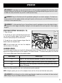
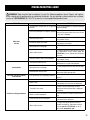
CHANGING SPEEDS
The variable speed dial allows you to adjust the blade speed between 2000 and 6000 RPM. The optimal blade speed
depends on the type and thickness of the workpiece. Turn the dial towards “1” to reduce blade speed; turn it towards
“6” to increase blade speed. Follow the guidelines below.
Speed Range Material Type
1-3 Gypsum- and cement-bonded fiberboard, soft plastics, non-ferrous metals
4-5 Hard plastics, fiberglass, paper and fabrics, particle- and hardboards, acrylic
5-6 Solid wood (hard or soft), plywood, veneered or coated boards, plastic-coated
boards, MDF boards
Reduce the cutting speed for clean cuts in soft and heat-sensitive materials.
NOTE: At higher speeds, you can cut the workpiece faster, but this will wear out the blade more quickly.
WARNING! Do not attempt to use the variable-speed function in order to use saw blades with lower no-load
speed ratings. Only use saw blades rated for at least 6000 RPM.
19
Plunge
Lock
Button
Power
Trigger
Fig. 18

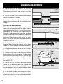
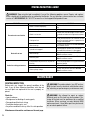
OPERATING THE SAW (FIG. 19)
1. Hold the tool firmly with both hands, using both the
front grip and the rear handle. Avoid placing your hand
on the workpiece while making a cut.
2. Place the workpiece with the “good” side down.
3. Set-up and support workpiece so cut is always on your
right side. The larger (left) side of saw’s base should be
on the part that does not fall off when a cut is made.
4. Securely clamp the workpiece so it will not move dur-
ing the cut. If you are cutting with the track, use two
clamps to clamp the track to the workpiece. If you are
cutting without the track, place a clamp as close to the
base of the saw as possible to support the workpiece.
Make sure the clamp is as close to the cut as possible
without getting in the way of the saw’s line of motion.
5. Draw a guideline along the desired path of the cut
before starting your saw or the cut. Set up the track to
meet the needs of your particular guide line (see “Setting
Up the Track” on page 15).
6. Keep the cord away from the cutting area. Position the
cord to prevent it from hanging up on the workpiece and
stop you from standing or tripping on the cord during
operation. Start the saw and make your cut.
CAUTION: To make sawing easier and safer, be sure to
move the tool forward gently in a straight line. Never
force or twist the saw during operation. Forcing or twist-
ing the tool will result in overheating the motor and will
increase the chances of dangerous kickback, possibly
causing severe personal injury. Do not pull the saw to-
wards you, or move the saw backwards, while cutting.
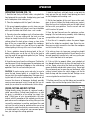
CROSS-CUTTING AND RIP CUTTING
Cutting directly across the grain of a piece of wood is
called crosscutting. Cutting wood lengthwise, or with
the grain, is referred to as rip cutting (or simply “rip-
ping”). Both types of cuts are performed in the same
manner with the exception of the methods used to sup-
port and secure the workpiece for cutting. After you have
secured the workpiece in position, positioned the cord
so it won’t be cut or hung up, performed the saw set-up
adjustments, made the necessary measurements, drawn
a straight guide line, and put on your personal protec-
tion, you can begin the cutting operation.
OPERATION
1. Hold the tool firmly with both hands, using both the
front grip and the rear handle. Avoid placing your hand
on the workpiece while making a cut.
2. Set the front portion of the saw’s base on the work-
piece to be cut without the blade making any contact.
Align the line-of-cut indicator notch on the right side of
the base with your guideline. Turn the saw on and wait
until it reaches full speed.
3. Ease the tool forward over the workpiece surface,
keeping it flat and advancing smoothly while following
your guideline until sawing is completed.
4. Once the cut is complete, release the power trigger.
Wait for the blade to completely stop. Raise the saw.
Now you can safely remove the saw from the workpiece
and set it out of the way.
5. To achieve clean cuts, keep your sawing line straight
while smoothly advancing forward. Do not force the saw
forward too quickly in order to try and hurry up the pro-
cess. Let the tool work at its own pace.
6. If the cut fails to properly follow your intended cut
line, do not attempt to turn or force the tool back to the
cut line. Doing so may bind the blade and lead to dan-
gerous kickback and possible serious injury. Do not pull
the saw towards you, or move the saw backwards, while
cutting. Instead, release the switch trigger, wait for the
blade to stop, and then remove the tool. Realign saw on
a new cut guide line and start the cut again.
7. Position yourself in a way that allows you to avoid the
wooden chips and dust being ejected from the saw.
20
Without Track
Fig. 19
Clamp
Close to
Base
With
Track
Page is loading ...
Page is loading ...
Page is loading ...
Page is loading ...
Page is loading ...
Page is loading ...
Page is loading ...
Page is loading ...
-
 1
1
-
 2
2
-
 3
3
-
 4
4
-
 5
5
-
 6
6
-
 7
7
-
 8
8
-
 9
9
-
 10
10
-
 11
11
-
 12
12
-
 13
13
-
 14
14
-
 15
15
-
 16
16
-
 17
17
-
 18
18
-
 19
19
-
 20
20
-
 21
21
-
 22
22
-
 23
23
-
 24
24
-
 25
25
-
 26
26
-
 27
27
-
 28
28


Ask a question and I''ll find the answer in the document
Finding information in a document is now easier with AI
Related papers
Other documents
-
MasterForce 241-0706 User manual
-
Grizzly W1835 Owner's manual
-
-
Craftsman CMXETAX69434502 Owner's manual
-
 Grizzly PRO T33300 Owner's manual
-
REALCRAFT Soft Stop Installation guide
-
DeWalt DWS520 User manual
-
Master-force 241-0748 User manual
-
DeWalt DWS520K 12A TrackSaw Owner's manual
-
Delta 36-6022 User manual
