
R152-P30
Ampere® Altra® ARM Server - 1U 10-Bay
User Manual
Rev. 1.0

Copyright
© 2021 GIGA-BYTE TECHNOLOGY CO., LTD. All rights reserved.
The trademarks mentioned in this manual are legally registered to their respective owners.
Disclaimer
Information in this manual is protected by copyright laws and is the property of GIGABYTE.
Changes to the specications and features in this manual may be made by GIGABYTE without
prior notice. No part of this manual may be reproduced, copied, translated, transmitted, or
published in any form or by any means without GIGABYTE's prior written permission.
Documentation Classications
In order to assist in the use of this product, GIGABYTE provides the following types of documentation:
User Manual: detailed information & steps about the installation, conguration and use of this
product (e.g. motherboard, server barebones), covering hardware and BIOS.
User Guide: detailed information about the installation & use of an add-on hardware or
software component (e.g. BMC rmware, rail-kit) compatible with this product.
Quick Installation Guide: a short guide with visual diagrams that you can reference easily for
installation purposes of this product (e.g. motherboard, server barebones).
Please see the support section of the online product page to check the current availability of these
documents.
For More Information
For related product specications, the latest rmware and software, and other information please visit our website at
http://www.gigabyte.com
For GIGABYTE distributors and resellers, additional sales & marketing materials are available from our reseller
portal: http://reseller.b2b.gigabyte.com
For further technical assistance, please contact your GIGABYTE representative or visit
https://esupport.gigabyte.com/ to create a new support ticket
For any general sales or marketing enquiries, you may also message GIGABYTE server directly by email:
server[email protected]

Conventions
The following conventions are used in this user's guide:
NOTE!
Gives bits and pieces of additional
information related to the current topic.
CAUTION!
Gives precautionary measures to
avoid possible hardware or software problems.
WARNING!
Alerts you to any damage that might
result from doing or not doing specic actions.

Server Warnings and Cautions
Before installing a server, be sure that you understand the following warnings and cautions.
WARNING!
To reduce the risk of electric shock or damage to the equipment:
• Do not disable the power cord grounding plug. The grounding plug is an important safety
feature.
• Plug the power cord into a grounded (earthed) electrical outlet that is easily accessible at all
times.
• Unplug all the power cords from the power supplies to disconnect power to the equipment.
•
• Unplug the power cord from the power supply to disconnect power to the equipment.
• Do not route the power cord where it can be walked on or pinched by items placed against it.
Pay particular attention to the plug, electrical outlet, and the point where the cord extends from
the server.
WARNING!
To reduce the risk of personal injury from hot surfaces, allow the drives
and the internal system components to cool before touching them.
WARNING!
This server is equipped with high speed fans. Keep away from hazardous
moving fan blades during servicing.
WARNING!
This equipment is intended to be used in Restrict Access Location. The
access can only be gained by Skilled person.
Only authorized by well trained professional person can access the
restrict access location.
CAUTION!
• Do not operate the server for long periods with the access panel open or removed. Operat-
ing the server in this manner results in improper airow and improper cooling that can lead to
thermal damage.
• Danger of explosion if battery is incorrectly replaced.
• Replace only with the same or equivalent type recommended by the manufacturer.
• Dispose of used batteries according to the manufacturer’s instructions.

Electrostatic Discharge (ESD)
CAUTION!
ESD CAN DAMAGE DRIVES, BOARDS, AND OTHER PARTS. WE RECOMMEND THAT YOU
PERFORM ALL PROCEDURES AT AN ESD WORKSTATION. IF ONE IS NOT AVAILABLE,
PROVIDE SOME ESD PROTECTION BY WEARING AN ANTI-STATIC WRIST STRAP AT-
TACHED TO CHASSIS GROUND -- ANY UNPAINTED METAL SURFACE -- ON YOUR SERVER
WHEN HANDLING PARTS.
Always handle boards carefully. They can be extremely sensitive to ESD. Hold boards only by
their edges without any component and pin touching. After removing a board from its protective
wrapper or from the system, place the board component side up on a grounded, static free sur-
face. Use a conductive foam pad if available but not the board wrapper. Do not slide board over
any surface.
System power on/o: To remove power from system, you must remove the system from
rack. Make sure the system is removed from the rack before opening the chassis, adding, or
removing any non hot-plug components.
Hazardous conditions, devices and cables: Hazardous electrical conditions may be
present on power, telephone, and communication cables. Turn off the system and disconnect the
cables attached to the system before servicing it. Otherwise, personal injury or equipment dam-
age can result.
Electrostatic discharge (ESD) and ESD protection: ESD can damage drives,
boards, and other parts. We recommend that you perform all procedures in this chapter only at
an ESD workstation. If one is not available, provide some ESD protection by wearing an antistatic
wrist strap attached to chassis ground (any unpainted metal surface on the server) when handling
parts.
ESD and handling boards: Always handle boards carefully. They can be extremely
sensitive to electrostatic discharge (ESD). Hold boards only by their edges. After removing a
board from its protective wrapper or from the system, place the board component side up on a
grounded, static free surface. Use a conductive foam pad if available but not the board wrapper.
Do not slide board over any surface.
Installing or removing jumpers: A jumper is a small plastic encased conductor that slips
over two jumper pins. Some jumpers have a small tab on top that can be gripped with ngertips
or with a pair of ne needle nosed pliers. If the jumpers do not have such a tab, take care when
using needle nosed pliers to remove or install a jumper; grip the narrow sides of the jumper with
the pliers, never the wide sides. Gripping the wide sides can dam-age the contacts inside the
jumper, causing intermittent problems with the function con-trolled by that jumper. Take care to
grip with, but not squeeze, the pliers or other tool used to remove a jumper, or the pins on the
board may bend or break.

CAUTION!
Risk of explosion if battery is replaced incorrectly or with an incorrect type. Replace the battery
only with the same or equivalent type recommended by the manufacturer. Dispose of used bat-
teries according to the manufacturer’s instructions.

- 7 -
Table of Contents
Chapter 1 Hardware Installation .....................................................................................9
1-1 Installation Precautions .................................................................................... 9
1-2 Product Specications .................................................................................... 10
1-3 System Block Diagram ................................................................................... 13
Chapter 2 System Appearance ..................................................................................... 15
2-1 Front View ...................................................................................................... 15
2-2 Rear View ....................................................................................................... 15
2-3 Front Panel LED and Buttons ........................................................................ 16
2-4 Rear System LAN LEDs ................................................................................. 17
2-5 Power Supply Unit (PSU) LED ....................................................................... 18
2-6 Hard Disk Drive LEDs .................................................................................... 19
Chapter 3 System Hardware Installation ......................................................................21
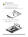
3-1 Removing Chassis Cover ............................................................................... 22
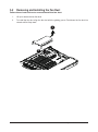
3-2 Removing and Installing the Fan Duct ........................................................... 23
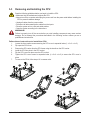
3-3 Removing and Installing the CPU .................................................................. 24
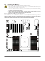
3-4 Installing the Memory ..................................................................................... 25
3-4-1 Eight Channel Memory Conguration .....................................................................25
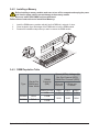
3-4-2 Installing a Memory ...............................................................................................26
3-4-3 DIMM Population Table ..........................................................................................26
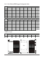
3-4-4 Altra Platform DDR4 Suggest Conguration Table .................................................27
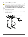
3-5 Installing the PCI Expansion Card ................................................................. 28
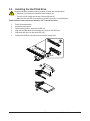
3-6 Installing the Hard Disk Drive ......................................................................... 29
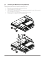
3-7 Installing the Mezzanine Card (Optional) ....................................................... 30
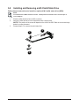
3-8 Installing and Removing an M.2 Solid State Drive ......................................... 31
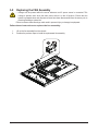
3-9 Replacing the FAN Assembly ......................................................................... 32
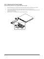
3-10 Replacing the Power Supply .......................................................................... 33
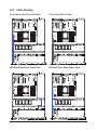
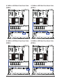
3-11 Cable Routing ................................................................................................ 34
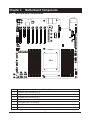
Chapter 4 Motherboard Components ...........................................................................37
4-1 Motherboard Components ............................................................................. 37
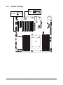
4-2 Jumper Settings ............................................................................................. 39
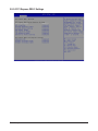
Chapter 5 BIOS Setup ..................................................................................................41
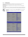
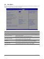
5-1 The Main Menu .............................................................................................. 43
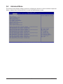
5-2 Advanced Menu ............................................................................................. 45
5-2-1 Trusted Computing .................................................................................................46
5-2-2 ACPI Settings .........................................................................................................47

- 8 -
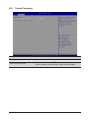
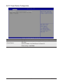
5-2-3 General Watchdog ..................................................................................................48
5-2-4 APEI Conguration .................................................................................................49
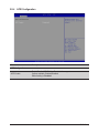
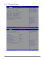
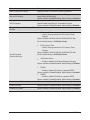
5-2-5 PCI Subsystem Settings .........................................................................................50
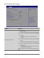
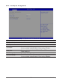
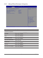
5-2-6 Info Report Conguration .......................................................................................57
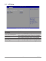
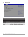
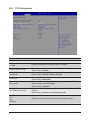
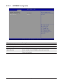
5-2-7 USB Conguration ..................................................................................................58
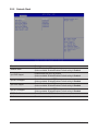
5-2-8 Network Stack ........................................................................................................59
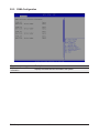
5-2-9 NVMe Conguration ...............................................................................................60
5-2-10 Power Restore Conguration .................................................................................61
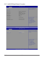
5-2-11 Intel(R) I350 Gigabit Network Connection ..............................................................62
5-2-12 MAC IPv4 Network Conguration ...........................................................................64
5-2-13 MAC IPv6 Network Conguration ...........................................................................65
5-3 Chipset Setup Menu ....................................................................................... 66
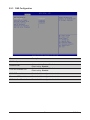
5-3-1 CPU Conguration ..................................................................................................67
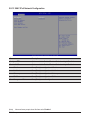
5-3-2 Memory Slot Information ........................................................................................68
5-3-3 RAS Conguration ..................................................................................................71
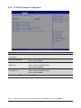
5-3-4 PCIE Root Complex Conguration .........................................................................72
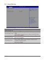
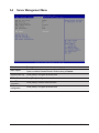
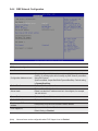
5-4 Server Management Menu ............................................................................. 73
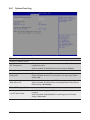
5-4-1 System Event Log ..................................................................................................74
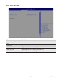
5-4-2 BMC self test ..........................................................................................................75
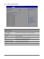
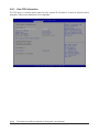
5-4-3 View FRU Information ............................................................................................76
5-4-4 BMC Network Conguration ...................................................................................77
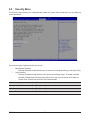
5-5 Security Menu ................................................................................................ 78
5-5-1 Secure Boot ............................................................................................................79
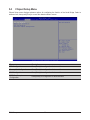
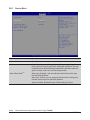
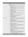
5-6 Boot Menu ...................................................................................................... 81
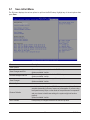
5-7 Save & Exit Menu ........................................................................................... 83
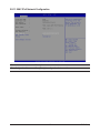
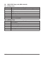
5-8 BIOS POST Beep code (AMI standard) ......................................................... 84
5-8-1 PEI Beep Codes .....................................................................................................84
5-8-2 DXE Beep Codes ...................................................................................................84

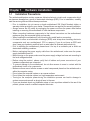
- 9 - Hardware Installation
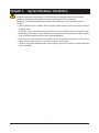
1-1 Installation Precautions
The motherboard/system contain numerous delicate electronic circuits and components which
can become damaged as a result of electrostatic discharge (ESD). Prior to installation, carefully
read the service guide and follow these procedures:
• Prior to installation, do not remove or break motherboard S/N (Serial Number) sticker or
warranty sticker provided by your dealer. These stickers are required for warranty validation.
• Always remove the AC power by unplugging the power cord from the power outlet before
installing or removing the motherboard or other hardware components.
• When connecting hardware components to the internal connectors on the motherboard,
make sure they are connected tightly and securely.
• When handling the motherboard, avoid touching any metal leads or connectors.
• It is best to wear an electrostatic discharge (ESD) wrist strap when handling electronic
components such as a motherboard, CPU or memory. If you do not have an ESD wrist
strap, keep your hands dry and rst touch a metal object to eliminate static electricity.
•
Prior to installing the motherboard, please have it on top of an antistatic pad or within an
electrostatic shielding container.
• Before unplugging the power supply cable from the motherboard, make sure the power
supply has been turned off.
• Before turning on the power, make sure the power supply voltage has been set according to
the local voltage standard.
• Before using the product, please verify that all cables and power connectors of your
hardware components are connected.
• To prevent damage to the motherboard, do not allow screws to come in contact with the
motherboard circuit or its components.
• Make sure there are no leftover screws or metal components placed on the motherboard or
within the computer casing.
• Do not place the computer system on an uneven surface
.
• Do not place the computer system in a high-temperature environment.
• Turning on the computer power during the installation process can lead to damage to
system components as well as physical harm to the user.
• If you are uncertain about any installation steps or have a problem related to the use of the
product, please consult a certied computer technician.
Chapter 1 Hardware Installation

Hardware Installation - 10 -
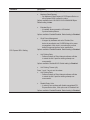
1-2 Product Specications
Socket
Socket
Security
Security ServerOperating Properties
Power S upply
CPU Ampere® Altra® Max or Altra® Processor
Single processor, 7nm technology
Up to 128-core per processor
Socket
Socket
Security
Security ServerOperating Properties
Power S upply
Socket Single socket
LGA4926
Socket
Socket
Security
Security ServerOperating Properties
Power S upply
Chipset System on Chip
Socket
Socket
Security
Security ServerOperating Properties
Power S upply
Memory 16 x DIMM slots
DDR4 memory supported only
8-Channel memory architecture
RDIMM modules up to 256GB supported
LRDIMM modules up to 256GB supported
Up to 4TB of memory capacity supported per processor
Memory speed: Up to 3200 MHz
NTOE! Only supports congurations with 1,2, 4, 6, 8,12, or 16 DIMMs
Socket
Socket
Security
Security ServerOperating Properties
Power S upply
LAN 2 x 1GbE LAN ports (1 x Intel® I350-AM2)
1 x 10/100/1000 Mbps management LAN
Socket
Socket
Security
Security ServerOperating Properties
Power S upply
Video Integrated in Aspeed® AST2500
2D Video Graphic Adapter with PCIe bus interface
1920x1200@60Hz 32bpp
Socket
Socket
Security
Security ServerOperating Properties
Power S upply
Storage 6 x 2.5" SATA/SAS hot-swappable HDD/SSD bays from CRAO338 SAS RAID Card
4 x 2.5" NVMe hot-swappable HDD/SSD bays from onboard NVMe ports
Socket
Socket
Security
Security ServerOperating Properties
Power S upply
RAID RAID 0/ 1/ 1E/ 10
Socket
Socket
Security
Security ServerOperating Properties
Power S upply
Expansion Slot Riser Card CRS101D:
1 x PCIe x16 slot (Gen4 x16), Full height half-length
1 x OCP 2.0 mezzanine slot, occupied by CRAO338 SAS RAID Card
2 x M.2 slots:
M-key
PCIe Gen4 x4
Supports NGFF-2242/2260/2280/22110 cards
NOTE:
We reserve the right to make any changes to the product specications and product-related
information without prior notice.

- 11 - Hardware Installation
Socket
Socket
Security
Security ServerOperating Properties
Power S upply
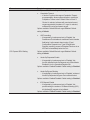
Internal I/O 2 x M.2 slots
1 x USB 3.0 header
1 x USB 2.0 header
1 x TPM header
1 x Front panel header
1 x HDD back plane board header
1 x PMBus connector
1 x IPMB connector
1 x Clear CMOS jumper
1 x Buzzer
Socket
Socket
Security
Security ServerOperating Properties
Power S upply
Front I/O 1 x USB 3.0
1 x Power button with LED
1 x ID button with LED
1 x Reset button
2 x LAN activity LEDs
1 x HDD activity LED
1 x System status LED
Socket
Socket
Security
Security ServerOperating Properties
Power S upply
Rear I/O 3 x USB 3.0
1 x VGA
1 x Debug port
2 x RJ45
1 x MLAN
1 x ID button with LED
Socket
Socket
Security
Security ServerOperating Properties
Power S upply
Backplane I/O Backplane P/N: 9CBP10A3NR-00
Speed and bandwidth:
PCIe Gen3 x4, SAS 12Gb/s, SATA 6Gb/s
Socket
Socket
Security
Security ServerOperating Properties
Power S upply
TPM 1 x TPM header with SPI interface
Optional TPM2.0 kit: CTM010

Hardware Installation - 12 -
Socket
Socket
Security
Security ServerOperating Properties
Power S upply
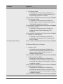
Power Supply 2 x 650W redundant power supply
80 PLUS Platinum
AC Input:
100-240Vac/ 10-5A, 50-60Hz
DC Input:
190-310V, 5-3A
DC Output:
650W
+12V/52.9A
+5Vsb/4.0A
Socket
Socket
Security
Security ServerOperating Properties
Power S upply
System
Management
Aspeed® AST2500 management controller
GIGABYTE Management Console (AMI MegaRAC SP-X) web interface
Dashboard
HTML5 KVM
Sensor Monitor (Voltage, RPM, Temperature, CPU Status …etc.)
Sensor Reading History Data
FRU Information
SEL Log in Linear Storage / Circular Storage Policy
Hardware Inventory
Fan Prole
System Firewall
Power Consumption
Power Control
LDAP / AD / RADIUS Support
Backup & Restore Conguration
Remote BIOS/BMC/CPLD Update
Event Log Filter
User Management
Media Redirection Settings
PAM Order Settings
SSL Settings
SMTP Settings
Socket
Socket
Security
Security ServerOperating Properties
Power S upply
Environment
Ambient
Temperature
Relative
Humidity
Operating temperature: 10°C to 35°C
Non-operating temperature: -40°C to 60°C
Operating humidity: 8-80% (non-condensing)
Non-operating humidity: 20%-95% (non-condensing)
Ambient temperature limited to 30°C if using 280W CPU
Socket
Socket
Security
Security ServerOperating Properties
Power S upply
System
Dimension
1U
438mm (W) x 43.5mm (H) x 660mm (D)

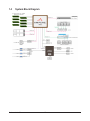
Hardware Installation - 13 -
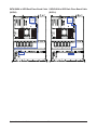
1-3 System Block Diagram

Hardware Installation - 14 -
This page intentionally left blank

- 15 - System Appearance
Chapter 2 System Appearance
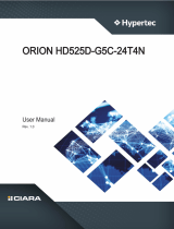
2-1 Front View
No. Description
1. Front USB 3.0 Port
2. Front Panel LEDs and Buttons
NOTE! The Orange HDD Latch Supports NVMe
• Please Go to Chapter 2-3 Front Panel LED and Buttons for detail description of function
LEDs.
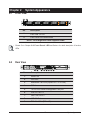
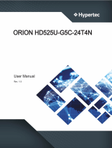
2-2 Rear View
No. Description
1. Serial Port
2. VGA Port
3. Mezzanine Card Slot (Option/OCP V2.0 Card)
4. ID Button
5. 10/100/1000 Server management LAN port
6. USB 3.0 Port x 2
7. GbE LAN Port x 2
8. USB 3.0 Port
9. PCIe Card Slot (PCIe x16)
12
HDD#0
HDD#1
HDD#2
HDD#3
HDD#4
HDD#5
HDD#6
HDD#7
HDD#8
HDD#9
21 3 5
46 7 8
9
PSU1PSU2

System Appearance - 16 -
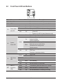
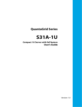
2-3 Front Panel LED and Buttons
L1 L2
2
4
6
1
3
5
7
No. Name Color Status Description
1. Reset Button Press the button to reset the system.
2. ID Button Press the button to activate system identication
3. Power button
with LED
Green On System is powered on
Green Blink System is in ACPI S1 state (sleep mode)
N/A Off
• System is not powered on or in ACPI S5 state
(power off)
• System is in ACPI S4 state (hibernate mode)
4. System
Status LED
Green On System is operating normally.
Amber
On
Critical condition, may indicate:
System fan failure
System temperature
Blink
Non-critical condition, may indicate:
Redundant power module failure
Temperature and voltage issue
Chassis intrusion
N/A Off
System is not ready, may indicate:
POST error
Processor or terminator missing
5. HDD Status
LED
Green On HDD locate
Blink HDD access
Amber On HDD fault
Green/
Amber Blink HDD rebuilding
N/A Off No HDD access or no HDD fault.
6./7.
LAN 1/2
Active/Link
LEDs
Green On Link between system and network or no access.
Green Blink Data trasmission or receiving is occuring
N/A Off No data transmission or receiving is occuring

System Appearance - 17 -
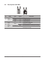
2-4 Rear System LAN LEDs
No. Name Color Status Description
1. 1GbE
Speed LED
Yellow On 1 Gbps data rate
Green On 100 Mbps data rate
N/A Off 10 Mbps data rate
2.
1GbE
Link/
Activity
LED
Green
On Link between system and
network or no access
Blink Data transmission or receiving is occurring
N/A Off No data transmission or
receiving is occurring
1 2
1 2
1 2

- 18 - System Appearance
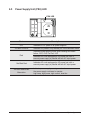
2-5 Power Supply Unit (PSU) LED
State Description
OFF Indicates no AC power to all power supplies
1Hz Blink GREEN Indicates AC present/ only standby on/ Cold redundant mode
Red
Indicates power supply critical event causing shut down:
failure, OCP, OVP, Fan Fail, UVP
Indicates AC cord unplugged or AC power lost; with a
second power supply in parallel still with AC input power
1Hz Blink Red Indicates AC cord unplugged or AC power lost; with a
second power supply in parallel still with AC input power.
1Hz Blink Red/Green
Alternative
Indicates power supply warning events where
the power supply continues to operate:
high temp, high power, high current, slow fan.
PSU LED

- 19 - System Appearance
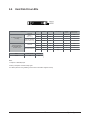
2-6 Hard Disk Drive LEDs
NOTE:
*1: Depends on HBA/Utility Spec.
*2: Blink cycle depends on HDD's activity signal.
*3: If HDD is pulled out during rebuilding, the disk status of this HDD is regarded as faulty.
/('
/('
Disk LED
(LED on
Back Panel)
Removed HDD Slot
(LED on Back Panel)
Disk LED
Removed HDD Slot
RAID SKU
No RAID configuration
(via HBA)
RAID configuration
(via HW RAID Card or
SW RAID Card)
HDD
Access
HDD Present
(No Access)
BLINK (*2)
BLINK (*2)
OFF
OFF
OFF
OFF
OFF
--
--
--
--
--
--
--
--
OFF
(Low Speed: 2 Hz)
(*3)
(*3)
Rebuilding
HDD Fault
OFF
OFF
ON
OFF
ON
OFF
OFF
OFF
Locate
Amber
Green ON(*1)
ON
OFF
ON(*1)
OFF
Green
Amber
Green
ON(*1)Green
OFFAmber
Amber OFF
LED1
LED 2 HDD Present No HDD
Green ON OFF

System Appearance - 20 -
This page intentionally left blank
Page is loading ...
Page is loading ...
Page is loading ...
Page is loading ...
Page is loading ...
Page is loading ...
Page is loading ...
Page is loading ...
Page is loading ...
Page is loading ...
Page is loading ...
Page is loading ...
Page is loading ...
Page is loading ...
Page is loading ...
Page is loading ...
Page is loading ...
Page is loading ...
Page is loading ...
Page is loading ...
Page is loading ...
Page is loading ...
Page is loading ...
Page is loading ...
Page is loading ...
Page is loading ...
Page is loading ...
Page is loading ...
Page is loading ...
Page is loading ...
Page is loading ...
Page is loading ...
Page is loading ...
Page is loading ...
Page is loading ...
Page is loading ...
Page is loading ...
Page is loading ...
Page is loading ...
Page is loading ...
Page is loading ...
Page is loading ...
Page is loading ...
Page is loading ...
Page is loading ...
Page is loading ...
Page is loading ...
Page is loading ...
Page is loading ...
Page is loading ...
Page is loading ...
Page is loading ...
Page is loading ...
Page is loading ...
Page is loading ...
Page is loading ...
Page is loading ...
Page is loading ...
Page is loading ...
Page is loading ...
Page is loading ...
Page is loading ...
Page is loading ...
Page is loading ...
-
 1
1
-
 2
2
-
 3
3
-
 4
4
-
 5
5
-
 6
6
-
 7
7
-
 8
8
-
 9
9
-
 10
10
-
 11
11
-
 12
12
-
 13
13
-
 14
14
-
 15
15
-
 16
16
-
 17
17
-
 18
18
-
 19
19
-
 20
20
-
 21
21
-
 22
22
-
 23
23
-
 24
24
-
 25
25
-
 26
26
-
 27
27
-
 28
28
-
 29
29
-
 30
30
-
 31
31
-
 32
32
-
 33
33
-
 34
34
-
 35
35
-
 36
36
-
 37
37
-
 38
38
-
 39
39
-
 40
40
-
 41
41
-
 42
42
-
 43
43
-
 44
44
-
 45
45
-
 46
46
-
 47
47
-
 48
48
-
 49
49
-
 50
50
-
 51
51
-
 52
52
-
 53
53
-
 54
54
-
 55
55
-
 56
56
-
 57
57
-
 58
58
-
 59
59
-
 60
60
-
 61
61
-
 62
62
-
 63
63
-
 64
64
-
 65
65
-
 66
66
-
 67
67
-
 68
68
-
 69
69
-
 70
70
-
 71
71
-
 72
72
-
 73
73
-
 74
74
-
 75
75
-
 76
76
-
 77
77
-
 78
78
-
 79
79
-
 80
80
-
 81
81
-
 82
82
-
 83
83
-
 84
84


Ask a question and I''ll find the answer in the document
Finding information in a document is now easier with AI
Related papers
Other documents
-
 Hypertec ORION RS525U-G5C-24N2G Owner's manual
-
 Hypertec ORION HD525D-G5C-24T4N Owner's manual
-
 Hypertec ORION HD525U-G5C-24T4N Owner's manual
-
 QUANTA STRATOS S210 Series S210-X12RS Technical Manual
-
GIGA-BYTE TECHNOLOGY MX32-BS0 User manual
-
 QUANTA QuantaGrid S31A-1U User manual
-
Tyan GT62F-B5630 Service Engineer's Manual
-
Oracle X5-2L User manual
-
DFI PR611-C621 Preliminary User manual
-
Supermicro SYS-5017GR-TF-FM109 User manual


