Page is loading ...

1
lci1.com 574-537-8900 Rev: 03.09.18
Solera
®
Destination Awning
Installation and Owner’s Manual
(For Aftermarket Application)
CCD-0001255
Table of Contents
Introduction ..............................................2
Quick Facts ..............................................2
Preparation ...............................................2
Resources Required .....................................2
Installation ................................................3
Installing the Awning Rail (If Necessary) ................3
Assembling the Awning ..................................4
Mounting the Bottom Mounting Brackets ................4
Mounting the Awning ....................................5
Securing the Fabric ......................................6
Installing the Stop Bolt ...................................7
Operation .................................................7
Extending the Awning ...................................7
Retracting the Awning ...................................7
Fabric Replacement ......................................8
Fabric Removal ..........................................8
Installing Replacement Fabric ...........................9
Classic Awnings Fabric Replacement Turn Chart .......9
Maintenance - Solera
®
Awnings ....................... 10
Fabric Care ............................................ 10
Solera
®
Destination Awning Troubleshooting ........ 11
Awnbrella
™
Parts List .................................. 12
Resources Required ................................... 13
Installation .............................................. 13
Spacing Awnbrella Arms ���������������������������� 13
Drilling the Roller Tube ................................ 14
Mounting Hanger Blocks .............................. 15
Inserting Awnbrella Arms .............................. 15
Velcro
®
Stabilizers ..................................... 16
Proper Awning Extention for Awnbrella Arms ......... 17
Special Notes: ......................................... 17
Ground Support Introduction ......................... 18
Resources Required ����������������������������������� 18
Installation .............................................. 18
Removal of Ground Support .......................... 20
Solera
®
Destination
Awning
Installation and
Owner’s Manual
(For Aftermarket Applications)

2
lci1.com 574-537-8900 Rev: 03.09.18
Solera
®
Destination Awning
Installation and Owner’s Manual
(For Aftermarket Application)
CCD-0001255
Introduction
Destination campers (or seasonal campers) who set up
camp for extended stays will love the Solera
®
Destination
Awning because it provides an additional 20 percent more
shaded outdoor area. Not only does the Solera Destination
Awning provide a 9'8" projection canopy, it also comes
with a Solera
®
Awning Ground Support and the Solera
®
Awnbrella
®
to keep the fabric arched and taut to minimize
wind ap and enable rain runoff.
Quick Facts
• Operates like any manual spring roll up awning - basically
it’s a jlarger version of the Solera Classic Awning
• Wide selection of vinyl fabric and acrylic fabrics
• Comes standard with the Solera Awnbrella awning bows
which hold fabric tight and arched so water doesn’t pool
and debris can easily runoff
• Comes with a Solera Ground Support for added
stabilization
• Custom hardware color options available
Additional information about this product can be obtained
from www.lci1.com/support or by downloading the free
MyLCI app. The app is available on iTunes
®
for iPhone
®
and iPad
®
and also on Google Play
™
for Android
™
users.
iTunes
®
, iPhone
®
and iPad
®
are registered trademarks of
Apple Inc. Google Play
™
and Android
™
are trademarks of
Google Inc.
Preparation
FAILURE TO FOLLOW THE INSTRUCTIONS PROVIDED
IN THIS MANUAL MAY RESULT IN DEATH, SERIOUS
INJURY, COACH DAMAGE, OR VOIDING OF THE
COMPONENT WARRANTY�
MOVING PARTS CAN PINCH, CRUSH OR CUT� KEEP
CLEAR AND USE CAUTION�
Do NOT remove the following items until instructed:
1� Tape securing the fabric.
2� Cotter pins in the spring assemblies.
REMOVING THESE ITEMS PREMATURELY MAY CAUSE
SERIOUS INJURY OR PROPERTY DAMAGE�
Resources Required
• 1 to 3 People
• Cordless or Electric Drill or Screw Gun
• Appropriate Drive Bits, including ⁄" and ½"
• Screwdriver
• Ratchet
• ⁄" Socket
• ½" Socket
• ½" Wrench
• ⁄" Drill Bit
• Non-Permanent Method of Marking
• Silicone Sealant or Butyl Tape
• Silicone Lubricant
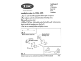
NOTE: Solera Destination Awning drive and idler heads
are preloaded with tension and secured with cotter pins
from the factory. If the cotter pins have been removed
or otherwise lost, and tension needs to be added to the
heads, use the turn chart (Fig.1) to add the correct number
of turns to the awning heads.
Fig.1
Size Turns
6' to 10'
4
11' to 14'
5
15' to 18'
6
19' and up
8
Classic Awnings Pre-Install Turn Chart

3
lci1.com 574-537-8900 Rev: 03.09.18
Solera
®
Destination Awning
Installation and Owner’s Manual
(For Aftermarket Application)
CCD-0001255
Installation
NOTE: All fasteners supporting the awning assembly MUST have a backer within the structure of the wall of the unit.
Refer to unit manufacturer for proper location.
Installing the Awning Rail (If Necessary)
NOTE: Awning rail not included.
1� Position the awning rail along the line where roof and wall meet.
NOTE: The awning rail MUST be level and parallel with the oor line of the unit (Fig.2).
2� After determining the awning rail’s proper location, mark its position with a non-permanent method of marking.
3� Seal the back of the awning rail.
4� Align the awning rail on the wall and secure with #10 x ¾" screws, using all fastener holes.
Assembling the Awning
NOTE: The head assemblies (Fig.3A) and support arm assemblies (Fig.3B) are numbered to ensure proper assembly.
Match the proper support arm assembly to the correct head assembly.
Floor Line
Awning Width = Head Bolt to Head Bolt
Side View
Front Facing View
A
B
E
D
B
90°
Fig.2
Letter Description
A Awning Rail
B Support Arm Assembly
C Roll Tube Assembly
D Lower Mounting Bracket
E Upper Mounting Bracket
C
Dotted line
= vertical
centerline
Dotted line
= Vertical
centerline
D

4
lci1.com 574-537-8900 Rev: 03.09.18
Solera
®
Destination Awning
Installation and Owner’s Manual
(For Aftermarket Application)
CCD-0001255
1� On a at surface, carefully lay out the support arm
assemblies and roll tube assembly. The cam lock MUST
be on the right side of the roll tube when facing the unit.
NOTE: Take care not to set the awning on any surface that
may damage the assembly or fabric.
2� Slide the left support arm assembly into the idler head
assembly of the roll tube. Align the holes and secure using
one (1) ¼-20 x ½" Phillips drive screw (Fig.4).
3� Repeat step 2 for the right support arm assembly.
4� Measure and conrm the width of the awning. The
distance is measured from head bolt to head bolt (Fig.2).
Mounting the Bottom Mounting Brackets
1� On the awning rail, mark the position of the support arm
assemblies using the head bolt to head bolt measurement.
Ensure that the support arm assemblies will not interfere with
any lights, vents or the operation of any windows or doors.
2� Using a non-permanent method of marking, mark a
perpendicular line from the mark on the awning rail down
to the oor line. This is the centerline of the support arm
assembly (Fig.2). Do this for both support arm assemblies.
3� Position the bottom bracket with the fastening points at the
oor line (Fig.5A) and center the bracket on the centerline mark
of the support arm assembly (Fig.5B). Mark the hole locations.
Using a ⁄" drill bit, pre-drill both holes. Apply a liberal amount
of sealant over the holes and attach the bracket using the ¼" x
2 ½" lag screws provided (Fig.5).
NOTE: All screws supporting the awning assembly MUST
have a backer within the structure of the wall of the unit. Refer
to unit manufacturer for proper location.
4� Repeat step 3 for the other side of the awning.
A
B
Fig.3 Fig.4 Fig.5
A
B

5
lci1.com 574-537-8900 Rev: 03.09.18
Solera
®
Destination Awning
Installation and Owner’s Manual
(For Aftermarket Application)
CCD-0001255
Mounting the Awning
1� Measure the distance from the awning rail channel to the
lower mounting bracket fastening point.
2� Compare the distance from the center of the roll tube
and the support arm assembly foot to the measurement in
Step 1 and adjust the support arm assembly to make both
distances equal.
A� Open the support arm assembly handle (Fig.6) and
slide the outer arm lower channel (channel#2) (Fig.7) up
or down to desired height. Close the handle and slide
the outer arm lower channel (channel#2) (Fig.7) until the
locking pin clicks into the nearest positioning hole.
3� Use a screwdriver to spread open either end of the
awning rail on the installation side (Fig.8A).
4� To protect the fabric from damage during installation, le
any sharp edges or burrs from the awning rail channel.
5� Use silicone lubricant and spray the inside of the awning
rail channel (Fig.8B).
6� Remove the packaging from the fabric. Unroll a small
portion of fabric, but not more than one rotation of fabric.
NOTE: The next step will require three people: One to feed
the polycord into the awning rail channel; two to walk the
support arm assemblies along the awning rail while the
fabric slides into position.
7� Slide the polycord into the awning rail channel and walk
the support arm assemblies and fabric down the awning
rail channel until the support arm assemblies are in line
with the centerline marks made previously.
8� Lift the support arm assembly up and secure the feet
into the previously installed bottom mounting brackets by
pressing the lever and opening the latch (Fig.9).
9� Center the upper mounting brackets on the support
arm assembly centerline marked previously and arrange
the upper mounting brackets to straddle the awning rail.
Tighten the black locking knob on the mount arm upper
channel (channel#3) (Fig.7).
NOTE: If adjustments need made so the upper mounting
brackets straddle the awning rail, loosen the black locking
push to open
Fig.6
Fig.7
Fig.8
channel#1
channel#2
channel#3
channel#4
locking knob
Fig.9
A
B

6
lci1.com 574-537-8900 Rev: 03.09.18
Solera
®
Destination Awning
Installation and Owner’s Manual
(For Aftermarket Application)
CCD-0001255
knob on the mount arm upper channel (channel#3) (Fig.7).
Slide the mount arm upper channel (channel#3) (Fig.7)
up or down as needed over the mount arm lower channel
(channel#4) (Fig.7).
10� Once the upper bracket is placed, mark and pre-drill
two ⁄" holes through the awning rail or unit. Apply a
liberal amount of sealant over the holes and attach the
upper mounting bracket using the ¼” x 3" lag screws
provided (Fig.10).
NOTE: All screws supporting the awning assembly MUST
have a backer within the structure of the wall of the unit.
Refer to the unit manufacturer for proper location. It is
acceptable that the lag screws go through the at portion
of the awning rail.
11� Repeat steps 9-11 for the other support arm assembly.
12� Firmly grasp the roll tube and head and remove the
safety cotter pin from each end of the roll tube. Keeping a
rm grasp on the roll tube and head, place the cam lock in
the roll up position.
13� Allow the fabric to slowly roll up.
Securing the Fabric
1� Roll the awning in and out several times to ensure that
the fabric is square on the roll tube.
2� Secure the fabric in the awning rail no more than 1"
inside the edge of the fabric on both ends using a #6 x
½"
hex head screw. Install the screw down through the awning
rail into the fabric and the polycord (Fig.11).
upper mounting
bracket
awning rail
Fig.10
FAILURE TO MAINTAIN CONTROL OF THE ROLL
TUBE, FABRIC AND SUPPORT ARM ASSEMBLIES
MAY RESULT IN SERIOUS PERSONAL INJURY OR
PROPERTY DAMAGE�
USE CARE WHEN REMOVING THE COTTER PINS THE
COTTER PINS ARE HOLDING THE PRE-WOUND TENSION
OF THE SPRING� FAILURE TO SECURELY HOLD THE
ROLL TUBE MAY ALLOW THE ROLL TUBE TO RAPIDLY
ROLL UP AND CAUSE PERSONAL INJURY OR DAMAGE�
Fig.11
awning rail
1"
fabric
stitching

7
lci1.com 574-537-8900 Rev: 03.09.18
Solera
®
Destination Awning
Installation and Owner’s Manual
(For Aftermarket Application)
CCD-0001255
Operation
Extending the Awning
1� Make sure the black locking knobs on the mount/rafter
arm upper channel (channel#3) (Fig.7) are loosened and
pinch the travel locks together to release the outer arm
from the mount/rafter arm.
2� Flip cam lock down to the extend position.
3� Using the pull rod, start pulling the awning outward until
full extension is complete.
4� Slide the mount/rafter arms all the way to the top of the
outer arm and make sure they lock into place.
5� Pull on the mount/rafter arm to insure the fabric is taut
and tighten the black locking knob to lock it into place.
6� Raise the outer arms to the desired height by releasing
the support arm assembly handle and allow the outer arm
upper channel (channel#1) (Fig.7) to slide on the outer
arm lower channel (channel#2) (Fig.7) Once to the desired
height let go of the support arm assembly handle to lock
the arm at this position.
7� Slide the pull strap to one end or the other and wrap it
around the arm to get it out of the way.
Optional Car Port Position
1� Once all the above steps are complete, remove the outer
arm from the side of the unit by releasing the lever on the
lower mounting bracket.
2� Walk the awning out until the outer arm is straight up
and down and let it set on the ground.
3� Make sure to secure the foot of the outer arm to the
ground with the provided stakes.
Retracting the Awning
NOTE: Do NOT retract the awning while in carport mode.
1� If in car portmode, remove the stakes from the foot of
the outer arm. Then walk the outer arm back to the unit
and secure it to the lower mounting bracket on the sidewall
of the unit. Do this for both ends.
2� Take the awning pull strap and return it to the center of
the awning roll tube.
Installing the Stop Bolt
1� Make sure the awning is retracted completely.
2� Make sure the centerline of the roll tube is level with or
slightly higher than the centerline of the awning rail (Fig.2).
The bottom of the roll tube MUST not be higher than the
awning rail.
3� Adjust support arm assemblies if necessary.
A� Open the outer arm handle (Fig.12) and slide the outer
arm upper channel (channel#1) (Fig.7) up or down to the
desired height. Close the handle and slide the outer arm
upper channel (channel#1) (Fig.7) on the outer arm lower
channel (channel#2) (Fig.7) until the locking pin clicks into
the nearest positioning hole.
4� With a non-permanent method of marking, mark the
position of the stop hole that is directly below the outer arm
upper channel (channel#1) (Fig.7).
5� From the inside of the outer arm lower channel
(channel#2) (Fig.7), insert a ⁄" bolt through the hole.
Secure with a star washer and a ⁄" acorn nut using ½"
socket and wrench (Fig.13).
NOTE: It may be necessary to lift the outer arm upper
channel (channel#1) (Fig.7) to tighten the acorn nut.
NOTE: Repeat step 3 to 5 for the other support arm.
Fig.12
Fig.13

8
lci1.com 574-537-8900 Rev: 03.09.18
Solera
®
Destination Awning
Installation and Owner’s Manual
(For Aftermarket Application)
CCD-0001255
Fabric Replacement
Fabric Removal
1� Remove the drip cap (if equipped) from the end the
fabric will be removed from.
2� Remove the #6 x ½" hex head screws located on the
awning rail (2 total). Set screws aside (Fig.11).
3� Extend the awning out completely by sliding the mount/
rafter arms all the way to the top of the outer arm and make
sure they lock into place and insert cotter pins (Fig.14).
3� Lower the roll tube by holding the outer arm and
releasing the support arm assembly handle on the side.
Let the outer arm upper channel (channel#1) (Fig.7) slide
down the outer arm lower channel (channel#2) (Fig.7) until
it rests on the acorn nut. Repeat this for the other end.
4� Loosen the black locking knob and unlock the mount/
rafter arm by releasing the spring clip from the top of the
head assembly. Allow the mount/rafter arm to slide all the
way down toward the bottom of the outer arm. Repeat this
for both ends.
5� Take a rm hold on the awning strap and release the
tension on the springs by ipping the cam lock up to the
roll in position.
6� Walk the awning in toward the unit. Hook the pull rod
into the pull strap before the strap gets too high. Using the
pull rod, walk the awning to the fully-closed position.
7� Lock the arms for travel mode by compressing the
outer arm and mount/rafter arm together until the red tab
disappears. Then tighten the black locking knob.
7� Working together, remove the roll tube assembly (which
includes the drive/idler head assemblies) from the awning
rail and support arms by sliding the assembly along the
awning rail until clear.
Fig.15
fastener
Fig.14
cotter pin
idler side shown
4� Pull on the mount/rafter arm to insure the fabric is taut
and tighten the black locking knob to lock it into place. As a
precaution, tape the cam lock in the roll out position.
5� On the end of the awning rail the fabric will be removed
from, remove the upper mounting bracket from the unit
wall. Allow the mount/rafter arm to pivot out of the way.
6� Remove the drive head assembly and idler head
assembly retaining fasteners from the outer arms to
separate the components (Fig.15).
FAILURE TO SUPPORT THE ROLL TUBE, FABRIC AND
DRIVE/IDLER HEAD ASSEMBLIES DURING REMOVAL MAY
RESULT IN SERIOUS INJURY OR PROPERTY DAMAGE�
8� Place the removed assembly onto a level area.
9� Have someone securely hold the idler head and roll tube.
10� Hold the drive head assembly securely (there will
be tension to be released) and remove the drive head
assembly cotter pin.
FAILURE TO MAINTAIN CONTROL OF THE ROLL TUBE,
FABRIC AND DRIVE/IDLER HEAD MAY RESULT IN
SERIOUS INJURY OR PROPERTY DAMAGE�
NOTE: If the awning is 6' in length it will only need one
cotter pin for the drive side end cap.

9
lci1.com 574-537-8900 Rev: 03.09.18
Solera
®
Destination Awning
Installation and Owner’s Manual
(For Aftermarket Application)
CCD-0001255
11� Flip the cam lock to the roll in position. Slowly rotate the
drive head assembly clockwise to release tension.
12� Mark the cam lock position on the roll tube.
13� Remove the three screws holding the drive head
assembly end cap on the roll tube and set the drive head
assembly aside.
14� Mark the roll tube grooves containing the polycords
prior to removing the fabric from the roll tube.
15� Remove the two screws holding the fabric in place on
the roll tube.
16� To remove the fabric, gently pull the roll tube from one
end, while another person holds the fabric in place.
Installing Replacement Fabric
1� Unroll the replacement fabric so that the polycords are
parallel with the roll tube.
2� Gently slide the roll tube on to the two polycords of the
fabric, making sure that the non-printed side is touching
the roll tube (Fig.16).
6� Using the three screws previously removed from the end
caps, attach the drive head and idler head assemblies to
the roll tube, making sure the orientation is the same.
NOTE: Be sure the drive head assembly with the cam lock
is on the right-hand side of the awning.
7� Secure the idler head and roll tube to the work bench.
8� Rotate the drive head assembly counterclockwise the
number of turns stated on the turn chart (Fig.18). Insert a
cotter pin into the end cap into the shaft on the drive head
assembly.
Fig.16
fabric
polycord in
roll tube channel
slide
FAILURE TO MAINTAIN CONTROL OF THE ROLL TUBE,
FABRIC AND DRIVE/IDLER HEADS MAY RESULT IN
INJURY OR PROPERTY DAMAGE�
Size Turns
6' to 10'
12
11' to 14'
13
15' to 18'
14
19' and up
16
Fig.18
roll
fabric
roll Tube
Fig.17
3� Center the fabric on the roll tube.
4� Apply the screws that were holding the polycords in
place on the roll tube.
5� Roll the fabric onto the roll tube (Fig.17). Make sure the
fabric stays snug and at to the roll tube with the printed
side facing away.

10
lci1.com 574-537-8900 Rev: 03.09.18
Solera
®
Destination Awning
Installation and Owner’s Manual
(For Aftermarket Application)
CCD-0001255
10� Unroll the fabric from the roll tube to allow the drive/
idler head assemblies to be installed into the outer arms.
11� Install the previously removed drive head assembly and
idler head assembly retaining bolts into the outer arms to
secure the components.
12� Reinstall the previously-removed support arm upper
mounting bracket to the unit wall.
13� Make sure the cam lock is in the roll out position and
remove cotter pins from the awning heads.
14� Retract and extend the awning several times (see
Operation section of the manual) to ensure that the fabric
is square on the roll tube.
15� Secure the fabric in the awning rail no more than 1"
inside the edge of the fabric on both ends using a #6 x ½"
hex head screw. Install the screw down through the awning
rail into the fabric and the polycord (Fig.19).
16� Reinstall the drip cap if previously equipped.
awning rail
1"
fabric
stitching
Fig.19
Maintenance
Fabric Care
NOTE: If the awning is retracted while wet, extend the
awning and let it dry as soon as conditions allow before
retracting. This will help prevent the formation of mildew
and add greatly to the life of the awning. Mildew does not
form on the fabric itself, but on the accumulated dust, dirt
and grime.
NOTE: Note: Periodically clean vinyl or woven acrylic
fabric using a mixture of ¼ cup of dish soap and 5 gallons
of warm water. Liberally apply the mixture on the top of the
fabric and retract the awning for 5 minutes. This will apply
the mixture to the bottom of the fabric as well. Extend the
awning and hose off with fresh water. Repeat if necessary.
Allow to dry before retracting.
FAILURE TO SUPPORT THE ROLL TUBE, FABRIC
AND DRIVE/IDLER HEAD ASSEMBLIES DURING
INSTALLATION MAY RESULT IN SERIOUS INJURY
OR PROPERTY DAMAGE�
Classic Awnings Fabric Replacement Turn Chart
9� Working together, install the roll tube assembly (which
includes the drive/idler head assemblies) to the awning rail
by sliding the assembly along the awning rail. Make sure
the awning will unroll with the printed side of the fabric up.

11
lci1.com 574-537-8900 Rev: 03.09.18
Solera
®
Destination Awning
Installation and Owner’s Manual
(For Aftermarket Application)
CCD-0001255
What is Happening? What Should Be Done?
Awning will not extend.
Check position of the cam lock (extend) roll out.
Ensure that the travel locks have been released from the outer arm.
Make sure the locking knob for the rafters has been loosened.
Check to see if the outer arm is resting on the mount/rafter arm.
If so, the outer arm height adjustment is not set properly.
Awning will not
retract or only
retracts part way.
Make sure the mount/rafter arms have been put in the stored position and the locking
knob has not been tightened.
Check position of cam lock (retract) roll in.
Ensure the outer arms have been placed in the closed/stored position.
Ensure the awning has the proper tension on it.
Ensure that the mount/rafter arm is not secured to the head
of the outer arm.
Fabric is loose or
sags on the edges
and middle.
Make sure the mount/rafter arms have been put in the stored position and the locking
knob has not been tightened.
Check position of cam lock (retract) roll in.
Ensure the outer arms have been placed in the closed/stored position.
Ensure the awning has the proper tension on it.
Ensure that the mount/rafter arm is not secured to the head of the outer arm.
Locking knob
will not tighten.
The nut for this is a thread part that tightens the arms together.
Open the awning and check when turning the knob that the nut is not stripped out. If it is
not stripped, it would require replacing both parts.
Mount/rafter arm
will not extend.
Make sure the locking knob has been loosened.
Make sure there is no debris in the track the arm slides in.
Make sure arm is not bent.
Awning will not
roll up straight.
Check to make sure fabric is centered on roll tube and also centered between the arms
attached to the unit.
If the fabric is not centered, move the screws on both ends of the awning and shift the
fabric accordingly.
Make sure there are screws at both ends of the fabric securing it to the roll tube and at
the awning rail. If there is only one screw at one end and not the other, the awning may
not roll up correctly.
Make sure the legs are square and straight.
Awning will not stay in
the rolled out position.
Check the cam lock. Signs of a faulty cam lock include:
The absence of a clicking noise when the awning is rolled out.
The awning rolling back up after it is placed in the stop position.
Troubleshooting chart

12
lci1.com 574-537-8900 Rev: 03.09.18
Solera
®
Destination Awning
Installation and Owner’s Manual
(For Aftermarket Application)
CCD-0001255
Awnbrella 3-arm package -
Part number 362237
Awnbrella Parts List
Letter Description Qty
A Awnbrella Arms Adjustable from 59" to 106" 2
B White Velcro
®
Pads with Adhesive Backing 2
C Black Velcro
®
Pads with Adhesive Backing 2
D Hanger Blocks 2
E Plastic Tightening Knobs 4
F
1-
¼" Self-Tapping Mounting Screws
4
Letter Description Qty
A Awnbrella Arms Adjustable from 59" to 106" 3
B White Velcro
®
Pads with Adhesive Backing 3
C Black Velcro
®
Pads with Adhesive Backing 3
D Hanger Blocks 3
E Plastic Tightening Knobs 6
F
1-
¼" Self-Tapping Mounting Screws
6
Awnbrella 2-arm package -
Part number 362238
A
B
C
D
E
F
A
B
C
D
E
F

13
lci1.com 574-537-8900 Rev: 03.09.18
Solera
®
Destination Awning
Installation and Owner’s Manual
(For Aftermarket Application)
CCD-0001255
Installation
Spacing Awnbrella Arms
Awnbrella Arms should be evenly spaced with no more
than 54" between each. To nd the proper spacing,
measure the width of the awning fabric and divide the
measurement by the recommended number of arms + 1.
Keep in mind that two arms make three sections, three
arms make four sections, etc. Divide the canvas into
sections not exceeding 54". See example to the right and
installations instructions on the next page.
Awnbrella installation is fairly simple. Customers with basic
mechanical skills should have no problem installing the
Awnbrella themselves.
Resources Required
• Cordless or Electric Drill or Screw Gun
• ⁄" Metal Drill Bit
• Phillips Screwdriver
• ¼" Fine Round File
• Punch
• Ladder
• Measuring Tape
Example: Awning canopy width measures 14' (168")
Recommended number of arms is 3 + 1 = 4
168" ÷ 4 = 42"
Space between each arm should be 42" wide
NOTE: Calculations will not always work out to be a
complete whole number. The outer most holes drilled into
the roller tube for the Awnbrella arms should not be placed
any closer than 42" from the end of the tube to protect the
roller tube spring.
awning width number of Awnbrella arms
10' - 14' 2 arms
14' - 18' 3 arms
18' - 22' 4 arms
22' - 27' 5 arms
168"
42"
42"
42"
42"
Example

14
lci1.com 574-537-8900 Rev: 03.09.18
Solera
®
Destination Awning
Installation and Owner’s Manual
(For Aftermarket Application)
CCD-0001255
Drilling the Roller Tube
1� With the awning fully extended,
measure the distance calculated
using the chart on the previous page
from the edge of the awning fabric.
(Fig�20). Mark the roller tube at that
predetermined distance and 1/2"
down from the fabric seam. (Fig.21).
This is where the rst Awnbrella
arm will later be installed. Continue
Fig.20 Fig.21
Fig.22
Fig.23
Fig.24
to make all measurements and
markings along the roller tube for
placement of the remaining arms.
Verify the correct spacing before
proceeding to the next step.
2� Using a metal punch, indent the
marks just made to create a dimple
to center the drill bit and keep it from
wandering (Fig.22).
3� Drill through the roller tube using a
7/16" bit (Fig.23).
4� Use a 1/4" round le to remove any
sharp burrs around the edges of the
holes (Fig.24).
NOTE: It is important that all the
holes drilled on the roller tube are
aligned at 1/2" down from the fabric
retaining seam.

15
lci1.com 574-537-8900 Rev: 03.09.18
Solera
®
Destination Awning
Installation and Owner’s Manual
(For Aftermarket Application)
CCD-0001255
Mounting Hanger Blocks
1� The hanger blocks MUST be
mounted on the exterior wall of the RV
directly beneath the awning hanger
rail and opposite the corresponding
holes previously drilled in the roller tube
(Fig.25). Measure and mark the position
on the RV wall for all Awnbrella arms.
2� Position the hanger blocks using the
marks as a center guide with the wide
side down and a
⁄" gap between the
hanger block and awning hanger rail.
Use a Phillips screwdriver or drill bit
to secure the hanger blocks with 1-
¼"
self-tapping screws. (Fig.26).
NOTE: Be sure there is backing behind
the skin of the RV where the hangers are
mounted to prevent pressure damage to
the wall. Do not overtighten the screws.
Inserting Awnbrella Arms
1� Thread the plastic tightening knobs
into the holes on the Awnbrella arms.
Extend one Awnbrella arm and measure
from the pointed tip end so that the knob
is approximately 8 inches from the end of
the C-channel. Tighten the knob (Fig.27).
2� Line up the remaining Awnbrella
arms and adjust them as done in step 1.
(Fig.28). Adjusting the arms now will make
it easier to properly insert them later.
3� Slide the pointed tip of the arm into the
hole in the roller tube (Fig.29).
NOTE: If the tip doesn’t slide fully into the
roller tube, use a round ¼" le to enlarge
the opening until it does.
4� Loosen the knob on the rubber tip
end of the arm and push the Awnbrella
arm up against the fabric. Slip the rubber
tip end of the arm into the hanger block
mounted on the RV (Fig.30). The harder
the Awnbrella arm is pushed against the
fabric, the more tension will be applied to
the awning.
5� Tighten the knob so the arm will
remain rigidly in place. Be sure Awnbrella
arms are secure so they don’t fall down.
Fig.25 Fig.26 Fig.27
Fig.28
Fig.29
Fig.30

16
lci1.com 574-537-8900 Rev: 03.09.18
Solera
®
Destination Awning
Installation and Owner’s Manual
(For Aftermarket Application)
CCD-0001255
Velcro
®
Stabilizers
Velcro stabilizers are included as
a safety precaution to secure the
Awnbrella and prevent the arms from
shifting or falling. Adhere a black
patch of Velcro to the back of the
Awnbrella arm and a white patch to
the canopy.
1� Take the Awnbrella arms down
from the coach. On the top side of
one Awnbrella arm (side without
adjustment knobs), wipe rubbing
alcohol to remove any grease or oils
from handling on the center of the
arm where the Velcro patch will be
installed. Measure 28-1/2" from either
end of the channel and mark with a
pencil (Fig.31). This is where to install
a black patch of Velcro.
2� Center the black Velcro patch
over the mark, peel off the protective
backing and press rmly into place
(Fig.32).
3� Line up all the arms and apply all
the patches following steps 1 and 2.
4� Reposition the Awnbrella arm back
into the hanger blocks and roller
tube, then use alcohol to clean the
awning fabric directly opposite the
black Velcro patch on the back of the
Awnbrella arm. Attach a white Velcro
patch to the black Velcro patch on
the Awnbrella arm (Fig.33).
Fig.31
Fig.32
Fig.33
Fig.34
5� Remove the clear protective lm
from the back of the Velcro (Fig.34).
Carefully place the Awnbrella arm
back into position, pressing it rmly
against the awning fabric.
6� Repeat steps 2 and 4 for each
Awnbrella arm.
NOTE: Leave the Awnbrella arms in
place for 48 hours to allow the adhesive
to set. Ideally, Velcro patches should
be installed when the temperature
is above 70º for the best bond. The
adhesive may not bond tightly to some
woven acrylic fabrics. Use vinyl contact
adhesive available at most hardware
stores for a better bond.

17
lci1.com 574-537-8900 Rev: 03.09.18
Solera
®
Destination Awning
Installation and Owner’s Manual
(For Aftermarket Application)
CCD-0001255
Special Notes:
• For proper water drainage, the roller tube MUST be at
least 6" lower than the hanger rail on the RV. Check
drainage with a water hose to be sure.
• Follow all care instructions recommended by the awning
manufacturer.
• The awning may stretch slightly where it meets Awnbrella
arms. This should present no problem in performance.
Canvas should be in good condition when using the
Awnbrella or it could rip.
• Lippert Components is not responsible for damage or
injury due to improper use or installation.
Proper Awning Extention for Awnbrella Arms
To use the awning in the carport position, put it in this
position before installing the arms and check to make sure
the holes in the roller bar are in an upward position (Fig.35).
Fig.35
Never:
• Leave the awning out in strong winds. Lippert
Components makes no claims regarding the
performance of this product in windy conditions.
• Drill into the roller tube closer than 42" from
each end to avoid striking the awning roller spring.
• Extend or retract the awning while the
Awnbrella arms are installed.
• Adjust the pitch of the awning side arms while
the Awnbrella arms are installed.

18
lci1.com 574-537-8900 Rev: 03.09.18
Solera
®
Destination Awning
Installation and Owner’s Manual
(For Aftermarket Application)
CCD-0001255
Ground Support Introduction
The Solera Ground Support gives added support to the
Solera Awnings as well as Carefree Awnings and Dometic
Awnings. Additional information about this product can be
obtained from www.lci1.com/support or by downloading
the free MyLCI app. The app is available on iTunes
®
for iPhone
®
and iPad
®
and also on Google Play
™
for
Android
™
users. iTunes
®
, iPhone
®
and iPad
®
are registered
trademarks of Apple Inc. Google Play
™
and Android
™
are
trademarks of Google Inc.
Installation
Fig.36
Fig.37
1� Measure the length of the roll tube (Fig.36).
center of roll tube
MOVING PARTS CAN PINCH, CRUSH OR CUT� KEEP
CLEAR AND USE CAUTION�
Resources Required
• Tape measure
• ⁄” wrench
• Cordless or electric drill or screw gun
• Appropriate drive bits
• Non-permanent method of marking
• ⁄” drill bit
• Hammer
2� Find the center of the roll tube and mark its location
(Fig.37).
3� Position the Ground Support assembly bracket at the
center of the roll tube (Fig.38).
NOTE: Keep the pull strap slot clear so accessories can be
used with the Ground Support assembly installed.
IF STAKING GROUND SUPPORT SHADE TO THE
GROUND, BE SURE TO DISABLEANY ANDALL SELF
RE-TRACKING WIND SENSING OPTIONS ON YOUR
AWNING� FAILURE TO DO SO COULD RESULT IN
DAMAGE TO THE AWNING AND UNIT�

19
lci1.com 574-537-8900 Rev: 03.09.18
Solera
®
Destination Awning
Installation and Owner’s Manual
(For Aftermarket Application)
CCD-0001255
Fig.39
7� Tighten the bolt to set the threaded insert fastener with
the ⁄” wrench while holding the threaded insert tool
stationary (Fig.41).
Fig.40
Fig.41
bolt
threaded
insert tool
threaded
insert tool
7/16” wrench
6� Place the bolt through the threaded insert tool and
into the threaded insert fastener. Then place the entire
assembly into the previously drilled hole (Fig.40).
8� Remove the bolt and threaded insert tool (Fig.42). The
roll tube will now have a threaded hole.
Fig.42
9� Place the Ground Support assembly bracket over the
threaded hole. Insert the tightening knob into the threaded
hole (Fig.43). Tighten to mount the Ground Support
assembly to the roll tube.
Fig.43
tightening
knob
ground
support
assembly
bracket
Fig.38
ground support assembly bracket
location for
threaded insert
4� Mark the location for the bolt at the center of the roll
tube using the Ground Support assembly bracket (Fig.38)
as a guide.
5� Drill a ⁄” hole at the mark made on the roll tube (Fig.39).

20
lci1.com 574-537-8900 Rev: 03.09.18
Solera
®
Destination Awning
Installation and Owner’s Manual
(For Aftermarket Application)
CCD-0001255
Fig.45
11� At the bottom of the Ground Support assembly,
hammer the two stakes through the holes into the ground
(Fig.46) for added stability.
Fig.46
Removal of Ground Support
1� Pull up the stakes from the end of the Ground Support
assembly (Fig.47).
Fig.47
2� Loosen adjustment knob (Fig.48). Slide the bottom leg
into the top leg. Re-tighten the adjustment knob.
Fig.48
3� Remove the tightening knob from the Ground Support
assembly (Fig.49). Remove the entire assembly from the
roll tube.
Fig.49
extend lower leg
and tighten
adjustment knob
top leg
bottom leg
tightening knob
lower leg
10� Loosen the adjustment knob of the Ground Support
assembly (Fig.44) and extend the lower leg of the assembly
to the ground (Fig.45) to support the roll tube. Re-tighten
the adjustment knob.
Fig.44
adjustment knob
/