Airmar M135M, M285HW, M422 1-1.5 kW Adjustable Angle Owner's manual

Type
Owner's manual

The Airmar M135M, M285HW, M422 1-1.5 kW Adjustable Angle transducer is designed for high-speed powerboats and racing sailboats. It features an adjustable angle from 0° to 22° to accommodate various hull deadrise angles. With a frequency range of 135-215 kHz (M135M) or 280-400 kHz (M285HW), it provides excellent target separation and bottom detail. Additionally, the M422 wideband model offers CHIRP technology for even greater resolution and target discrimination.

The Airmar M135M, M285HW, M422 1-1.5 kW Adjustable Angle transducer is designed for high-speed powerboats and racing sailboats. It features an adjustable angle from 0° to 22° to accommodate various hull deadrise angles. With a frequency range of 135-215 kHz (M135M) or 280-400 kHz (M285HW), it provides excellent target separation and bottom detail. Additionally, the M422 wideband model offers CHIRP technology for even greater resolution and target discrimination.

17-620-01 rev. 03 07/24/18
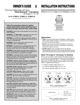
In-Hull: 1-1.5kW, Adjustable-angle
Depth Transducer
Wideband Model: M422
Chirp Models: M135M, M285HW
Patent http://www.airmar.com/patent.html
Applications
For fiberglass hulls only
Recommended for high-speed powerboats and racing sailboats
Accommodates a deadrise angle from 0° to 22°
Tools & Materials
Safety glasses
Dust mask
Ear protection
Adhesive tape
Pole
Detergent (some installations)
Weak solvent (such as alcohol)
Disk sander (some installations)
Thin sealable plastic bag (some installations)
Cable ties (some installations)
Water-based lubricant (such as K-Y® jelly) (some installations)
Angle finder
Carpenter’s square
Pencil
Bonding material (see www.airmar.com for additional brands):
Fiberglass resin: Bondo 401
West Marine #1937762)
or Marine-Tex epoxy putty (14 oz. pack)
or 3M™ Marine Adhesive/Sealant 5200
Propylene glycol (non-toxic antifreeze/coolant) 0.4 liter (14 fl. oz.)
Petroleum jelly
Torque-limiting screwdriver
Level
Grommet(s) (some installations)
Installation in a cored fiberglass hull (page 4):
Cutting tool 20cm or 8" hole
Miniature disk sander
Casting epoxy (Polypoxy #7035/7040) or resin
Paper cup
Stirrer
Mounting Location
About Fiberglass Hulls
The fiberglass hull below the transducer must be solid. Since the
hull absorbs acoustic energy, transmitting through the hull
reduces the transducer’s performance. Fiberglass hulls are often
reinforced in places for added strength or to reduce weight. These
cored areas contain balsa wood or structural foam which are poor
sound conductors. Do not locate the transducer over coring.
Choose a Location
Where the fiberglass is SOLID (no air bubbles are trapped in
the fiberglass resin) and where no coring, flotation material, or
dead air space is sandwiched between the inside skin and outer
skin of the hull.
Where the hull below the transducer will be in contact with the
water at all times.
Where the water flowing under the hull is smoothest with a min-
imum of bubbles and turbulence (especially at high speeds). Do
not mount the transducer in line with or near water intake or dis-
charge openings; or behind strakes, fittings, or hull irregularities
that will disturb the water flow.
Where the transducer beam will not be blocked by the keel or
propeller shaft(s).
Away from interference caused by power and radiation sources
such as: the propeller(s) and shaft(s), other machinery, other
echosounders, and other cables. The lower the noise level, the
higher the echosounder gain setting that can be used.
Where the deadrise angle of the hull does not exceed 22°.
Where there is space inside the vessel for the size of the base
and installing the transducer.
Chirp transducer—Mount in a cool well-ventilated area away
from the engine to avoid overheating the liquid inside the base.
Record the information found on the cable tag for future reference.
Part No._________________Date___________Frequency________kHz
Follow the precautions below for optimal
product performance and to reduce the risk of
property damage, personal injury, and/or death.
WARNING: Always wear safety glasses, a dust mask,
and ear protection when installing.
CAUTION: Chirp transducer—Always operate the
transducer in liquid. Operating in air will allow the
transducer to overheat resulting in failure.
CAUTION: The fiberglass hull below the transducer
must be SOLID. The transducer will not transmit
through coring material such as foam or balsa wood.
CAUTION: Chirp transducer—Do not install in the
engine compartment or other hot place. The
transducer may fail if the temperature of the liquid in
the base exceeds 60° C (140° F).
CAUTION: Never pull, carry, or hold the transducer by
the cable. This may sever internal connections.
CAUTION: Do not use an epoxy adhesive because it
is too brittle.
CAUTION: Never use solvents. Cleaner, fuel, sealant,
paint, and other products may contain solvents that can
damage plastic parts, especially the transducer’s face.
IMPORTANT: Please read the instructions completely
before proceeding with the installation. These
instructions supersede any other instructions in the
instrument manual if they differ.
OWNER S GUIDE & INSTALLATION INSTRUCTIONS
Testing the Selected Mounting Location
Establishing a Performance Baseline
The results of this test are used as a basis of comparison to
determine the best in-hull location for the transducer. The test
must be done in water to avoid overheating the transducer.
1. Take the boat to the maximum depth in which you will be
operating the echosounder. If deep water is not available, find a
location with at least 30m (100').
2. Remove the transducer from the base. Save the two screws and
rubbery washers and be careful of the O-ring in the groove on the
top of the base. Connect the transducer to the echosounder.
3. Tape the transducer to a pole with the cable side up. Hold it
over the side of the boat with the active face fully submerged
and parallel to the water surface (Figure 2).
4. Observe the echosounder’s performance and the depth reading.
Testing the Location
While the boat is at the same site (depth of water), test the
transducer inside the hull at the mounting location. Use one of the
methods below:
A.For a location near the stern and a minimal deadrise angle
Clean away any build-up of dirt and/or grease using detergent
or a weak solvent such as alcohol. Place the transducer against
the hull and allow bilge water to cover the surface where they
touch (Figure 3-A).
B.For a moderate deadrise angle—If the hull surface is not
smooth, grind it with a disc sander. Place the transducer inside a
thin plastic bag. Partially fill the bag with water and close it tightly
with a cable tie. Wet the surface of the hull and press the active
face of the transducer against it through the bag (Figure 3-B).
C.For any location—If the hull surface is not smooth, grind it with a
disc sander. Coat the active face of the transducer with a water-
based lubricant (such as K-Y
®
jelly). With a twisting motion, press
the face firmly against the hull (Figure 3-C). After testing, wipe all
traces of the lubricant from the transducer’s face.
Observe the echosounder’s performance, and compare it to the
baseline. Look for a stable depth reading that is similar to the
baseline. Compare the thickness and intensity of the bottom trace.
If the performance is close to the baseline, this is a good mounting
location. Remember, some energy is lost transmitting through the
hull. If the test reading differs markedly from the baseline, you will
need to find another location to install the transducer.
NOTE: If there is no reading or it is erratic, the transducer may be
positioned over coring which is absorbing the acoustic energy.
Choose another location. If no other location is available, check
with the boat manufacturer to be certain coring is present before
proceeding with the instructions for “Installation in a Cored
Fiberglass Hull” (page 4).
2
inboard
Figure 1. Best location for the transducer
pressure waves
1/3
full keel sailboat
displacement hull
(6-12")
fin keel sailboat
150-300mm
LWL
(Load Waterline Length)
stepped hull
planing hulls
Boat Types (Figure 1)
Displacement hull powerboat—Locate 1/3 of the way back
along the LWL and 150300mm (612") off the centerline. The
side of the hull where the propeller blades are moving
downward is preferred.
Planing hull powerboat—Mount well aft, on or near the
centerline, and well inboard of the first set of lifting strakes to
ensure that the transducer is in contact with the water at high
speeds. The side of the hull where the propeller blades are
moving downward is preferred.
Outboard and I/O—Mount just forward of the engine(s).
Inboard—Mount well ahead of the propeller(s) and shaft(s).
Stepped hull—Mount just ahead of the first step.
Fin keel sailboat—Mount to the side of the centerline and
forward of the fin keel 300600mm (12').
Full keel sailboat—Locate amidships and away from the keel
at the point of minimum deadrise angle.
Figure 2. Establishing a performance baseline
Figure 3. Testing the transducer at the selected location
AB C
active face
Copyright © 2005 - 2016 Airmar Technology Corp.
outboard and /IO
Copyright © 2016 Airmar Technology Corp.Copyright © 2016 Airmar Technology Corp.
Installation
Cored fiberglass hull—Follow separate instructions on page 4.
CAUTION: The base must be liquid-tight. To ensure a tight bond,
the hull surface under and around the base must be smooth, free
of paint or any other finish, clean, and dry.
CAUTION: The top of the transducer must be level when the
installation is complete.
1. Measure the deadrise angle of the hull at the selected location
(Figure 4). Measure carefully, because the installed transducer
must be within 5° of vertical.
2. The hull surface to be bonded must be smooth and free of paint
or any other finish. If the surface is rough, use a disk sander to
smooth an area 18cm (7") in diameter.
3. To ensure a tight bond, clean and dry both the selected area of
the hull and the underside of the base. Remove any dust,
grease, or oil with a weak solvent, such as alcohol.
4. Using a carpenter’s square, draw a line on
the hull perpendicular to the keel through
the center of the mounting location. This will
be used as a guideline to orient the base.
5. The numbers on the flange of the base
represent deadrise angles (Figure 5). On
the side of the flange between the KEEL
arrows, identify the number that most
closely corresponds to the deadrise angle
of the hull. Find the matching number on the
opposite side of the base. Keeping the two
keel arrows aimed toward the keel, align
both ribs with the guideline you drew on the
hull.
6. When you are satisfied that the location of the
transducer is optimal and the orientation of
the base corresponds to the deadrise angle of
the boat, you are ready to bond the base to
the hull. Use an approved bonding material
(see “Tools & Materials” on page 1). Follow
the manufacturer’s instructions for use. Press
the flange firmly in place to form a liquid-tight
seal. Allow the bonding material to cure.
7. After the bonding material has cured, pour
0.4 liter (14 fl. oz.) of propylene glycol into
the base. Do not over fill. Be sure to follow
the manufacturer’s directions for use.
8. Remove the O-ring from the base. Lubricate the O-ring with
petroleum jelly. This will help to seal the transducer to the base,
preventing the propylene glycol from leaking. Carefully return
the O-ring to the groove in the top of the base. Be sure it will not
be gouged or cut when the transducer is screwed in place. The
O-ring must be intact and well lubricated to make a liquid-tight
seal.
9. Carefully place the transducer into the base to avoid causing the
propylene glycol to overflow (Figure 6). Turn the transducer until
the number on the rim that corresponds to the deadrise angle is
directly over the alignment boss closest to the KEEL side of the
base. The transducer will drop into place when the two notches in
the rim fit around the two alignment bosses on the base.
10.Each of the two holes in the transducer’s rim will be directly over
an alignment boss. Secure the transducer to the base by inserting
a washer and screw into each hole. Tighten the screws using a
force not exceeding 1.8 N-m (1.3ft-lb). Do not over tighten.
3
deadrise
parallel to
hull
waterline
perpendicular
to keel
base
flange
Figure 5. Align the flange of the base (12° deadrise angle shown)
keel arrow
keel arrow
guideline
points toward keel
guideline
angle
NOTE: Lubricate
O-ring with
Figure 6. Installing the transducer in the base (12° deadrise angle shown)
O-ring
Copyright © 2016 - 2017 Airmar Technology Corp.
alignment
on rim of
petroleum jelly.
perpendicular to keel
Figure 4. Deadrise angle and guideline
Copyright © 2016 - 2017 Airmar Technology Corp.
alignment
top view
transducer
notches
alignment boss (2)
boss (2)
transducer
screw &
washer (2)
12° on
base
rim of transducer
guideline
perpendicular to keel
points toward keel
base
rib
alignment
rib
top view
KEEL
KEEL
K
E
E
L
flange
of base
rim of
transducer
flange
of base
4
11.When the transducer assembly is installed correctly, the top
will be level (Figure 7). If the deadrise angle is shallow, the
transducer may appear to be level even if it is not. Use a
carpenter's level to check the installation.
Cable Routing & Connection
CAUTION: If the transducer came with a connector, do not
remove it to ease cable routing. If the cable must be cut and
spliced, use Airmar’s splash-proof Junction Box No. 33-035 and
follow the instructions supplied. Removing the water-proof
connector or cutting the cable, except when using a water-tight
junction box, will void the transducer warranty.
1. Route the cable to the echosounder being careful not to tear the
cable jacket when passing it through the bulkhead and other
parts of the boat. Use grommets to prevent chafing. To reduce
electrical interference, separate the transducer cable from other
electrical wiring and sources of electrical noise. Coil any excess
cable and secure it in place with cable ties to prevent damage.
2. Refer to the instrument owner’s manual to connect the
transducer to the instrument.
Installation in a Cored Fiberglass Hull
Installation in a cored hull is difficult. The objective is to bond the
base to the inside surface of the hull’s outer skin while
preventing any moisture from penetrating the core.
CAUTION: There is no way to determine if the outer skin is solid
(no trapped air bubbles in the fiberglass) at the selected location
before cutting the inner skin.
1. Cut a 20cm or 8" hole through the inner skin and the core at the
selected location (Figure 8). The core material can be very soft.
Apply only light pressure to the hole saw after cutting through the
inner skin to avoid accidentally cutting the outer hull.
2. Remove the plug of core material, so the inner core of the hull is
fully exposed. Sand the inside surface of the outer skin using a
miniature disk sander. Slightly undercut the surrounding coring
if possible.
3. Clean and dry both the inside surface of the outer skin and the
transducer with a weak solvent, such as alcohol, to remove any
dust, grease, or oil.
4. Place the base in the cavity. Fill the gap between the base and
the hull with casting epoxy or resin following the manufacturer’s
directions for its use.
5. After the casting epoxy or resin has cured, proceed with
“Installation” (page 3).
Replacement Transducer & Parts
The information needed to order a replacement transducer is printed
on the cable tag. Do not remove this tag. When ordering, specify the
part number, date, and frequency in kHz. For convenient reference,
record this information on the top of page one.
Lost, broken, or worn parts should be replaced immediately.
Obtain parts from your instrument manufacturer or marine dealer.
Gemeco
USA
Tel: 803-693-0777
Airmar EMEA
Europe, Middle East, Africa
Tel: +33.(0)2.23.52.06.48
Figure 8. Installation in a cored fiberglass hull
transducer
inner skin
core
outer skin
fill with
casting epoxy
or resin
hull thickness
20cm (8")
Copyright © 2016 Airmar Technology Corp.
Copyright © 2016 - 2018 Airmar Technology Corp. All rights reserved.
35 Meadowbrook Drive, Milford, New Hampshire 03055-4613, USA
www.airmar.com
Figure 7. Completed installation is level
keel
NOTE: Top of
transducer
is level.
Copyright © 2016 Airmar Technology Corp.
carpenter’s
level
transducer
assembly
  • Page 1 1
  • Page 2 2
  • Page 3 3
  • Page 4 4

Airmar M135M, M285HW, M422 1-1.5 kW Adjustable Angle Owner's manual

Type
Owner's manual

The Airmar M135M, M285HW, M422 1-1.5 kW Adjustable Angle transducer is designed for high-speed powerboats and racing sailboats. It features an adjustable angle from 0° to 22° to accommodate various hull deadrise angles. With a frequency range of 135-215 kHz (M135M) or 280-400 kHz (M285HW), it provides excellent target separation and bottom detail. Additionally, the M422 wideband model offers CHIRP technology for even greater resolution and target discrimination.

Ask a question and I''ll find the answer in the document

Finding information in a document is now easier with AI