Page is loading ...

Check Box for These Contents
In the event of missing or defective parts please call our customer service dept. at
1 800 282 9346
(Mon. to Fri. 8:00 AM to 5:00 PM EST).
1. Keystone Top Lid with Inserts (2) - 10710-1
2. Arch Keystones (2) - 10684-1
3. Keystone Bottom Plate (2) - 10712-1
4. Arches (4) - 10687-1
5. Arch Rafters (8)
1 1/2” x 1 1/2” x 27.9" - 10727-1
6. Post Caps (4) - 10728-1
7. Side Panel Horizontal Rails
(4)
1 1/2” x 1 1/2” x 21.75” - 10729-1
8.
Sur-Fit Bracket for Side Panel Horizontals
(8) - 10730-1
9. Side Panel Vertical Spindles (4)
7/8” x 1 1/2” x 49" - 11198
10. Side Panel Horizontal Spindles (14)
1/4” x 1 1/2” x 15.25" - 10732-1
11. Posts (4)
4’ x 4’x 65.5" - 10733-1
12.
#8 x
1 1/2 in. (3.8 cm.)
Stainless Steel Screws
(for Sur-Fit Brackets)
(24) - 20005
13.
#8 x
2 1/2 in. (6.4 cm.)
Stainless Steel Screws
(for Keystone and Arch
to Post Connection) (24) - 20007
14. Side Panel Vertical Center Spindle (2) 7/8 x 1 1/2" x 49" - 10731-1
Tools You Will Need
• Hammer
• Tape Measure
• Level
• Stool or Short Ladder
• Shovel or Auger
• Cordless Drill
General Information
• Read Instructions through carefully before beginning assembly.
• When assembling components, place on a non-abrasive surface
(i.e. shipping box) to avoid scratching.
• We recommend an area approx 10’x 8’ for unobstructed assembling.
• You should not need to use excessive force when assembling components.
Please read through before starting assembly.
ASSEMBLY INSTRUC TIONS
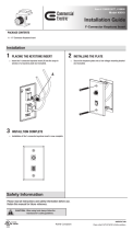
VA84240 The Nantucket Deluxe Arbor
12
5
9
8
7
1
6
4
2
1
(Not to scale)
3
94.1 in
94.1 in
65.6 in
22 in
30 in
52 in
60 in
IMPORTANT: CHECK THE INSIDE OF YOUR POSTS FOR ALLMATERIALS.
13
10
11
V3.9/031021
14
www.wearevita.com

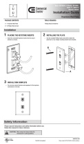
STEP ONE
2
Insert arches into arch keystone ensuring they terminate
ush to the internal connector.
Fasten the top of the arches to the keystone insert by
installing 2 1/2 in. (6.4 cm.) screws into the two anges on
either
side of the top of the insert.
Invert the arch system and install four screws 2 1/2 in. (6.4 cm.)
from the bottom of the keystone into the two
anges on
either side of the bottom of the insert. This will
connect the
bottom
of the arches to the insert.
Seal the bottom hole on keystone by inserting the bottom
plate as provided.
Install the top cap on the arch keystone.
Ensure keystone
cap is pushed down rmly so the cap locks into position.
Repeat for other arch.
Insert arch rafters (8) into the holes on the arches until they
bottom out inside the arches. There are “locking tabs” located
at each end of these rafters that once inserted into the holes
will lock into place.
Fit opposite arch system over rafters.
The Nantucket Deluxe Arbor
Assemble the Arch System
1
2
3
1
4
5
NOTE: There are locking tabs located at the ends of each
rafter. Once inserted and pushed into the routed holes, they
will lock into place and cannot be removed.
7
8
6
2
7
8
3
4
5

STEP T WO
3
The Nantucket Deluxe Arbor
STEP T WO
Insert the horizontal spindles into the middle verticle spindle
(holes on both sides).
Slide the two outer vertical spindles into position as illustrated
.
Layout the bottom horizontal rail and insert the vertical
spindles.
Slide top horizontal rail into position.
Repeat for other panel.
Assemble the Side Panels
1
2
3
4
5
1
2
3
4
STEP THREE
Attach Sur-Fit Brackets
Attach Sur-Fit Brackets (using small screws) onto posts using the
pre-drilled holes as guides. Single hole on the side of brackets
to face down.
Set out one post and slide the assembled side panel into.
Fasten horizontal rails into Sur-Fit Brackets using small screws.
L
ayout the opposite post and insert the nished side panel
with post connected.
Fasten horizontal rails into Sur-Fit Brackets using small screws.
Repeat for other side panel.
1
2
3
4
5
6
1
2
3
5
4
NOTE: Prior to installing Sur-Fit Brackets, insert a wood 4x4 post
approximately 5 ft. (152.4 cm.) up the inside of vinyl cavity
[purchase 4x4x8 to accomodate 3 ft. (91.45 cm.) in the ground]
if you intend to hang a gate, attach a fence or are located in a
high wind area.

3
STE P FO U R
Move the side panels
to their final location (you will need a
helper ).
When you have identified the location of each post, as
indicated
by the measurements on the first page of these
instructions,
mark the positions of the posts, then move the
panels aside.
Excavate four holes approx 33 in. (83.8 cm.) deep. The location
and e
xcavation of these four holes is the most critic al step and
should
be completed with care. The depth of these holes will
allow the
post extension (if chosen as option) joint to be hidden 3
in. (7.6 cm.)
under the ground.
Carefully move the
side panels back into position and level
both horizontal and vertically.
Check your measurements to confirm posts are placed
correctly to receive arch system. THIS IS A CRITICIAL STE P.
Inst all the Side Panels
1
2
3
4
5
Arbors must be well secured to prevent tipping over from
wind load, etc.
Into Ear th with Con
crete Footi ng
(Option One)
(Assuming posts h ave been extended)
* Do not backfill the holes with cement at this stage.
4
The Na ntucket Deluxe Ar bor
You have Three Options to Complete this Step.
( A ll purchased se parately)
OP TION ON E - If Your Arbor:
• is going to be installed with fencing or a gate
• is located in a high wind or hurricane area
• is located in ground conditions that are not level
Conside r Using:
A - 4x4
Professi onal Post Extension Kit
(30 in./76.2 cm. long), (Kit of 4)
• Purchase from Vita, www.wearevita.com
• Recommended to be installed in concrete footings
• Follow instructions included with the kit
- or -
B - 4 x 4 x 8 Long Wood Post (4)
• Purchase separate from your local lumberyard
• Recommended to be installed in concrete footing
OP TI O N T W O - If Your Arbor:
• is intended to be used as a stand alone garden accent or pathway
• is located on level ground
• Purchase from Vita, www.wearevita.com
• Instructions are included with the kit
1
(Posts have been extended with 4x4 Professio nal Post Extensio n Kit)
4
3
2
Level
(Measurements sh own are inside to inside of posts)
33 in.
83.8 cm.
10 in.
25.4 cm.
51.8 in.
131.6 cm.
22 in.
55.9 cm.
Conside r Using:
4” EZ Mount Post (Package of 4)

STEP FIVE
Temporarily position post caps on bottoms of arches.
With a helper, insert the bottom of the arches into the
posts until the arch rest on the stopper bolts.
Slide post caps down into position.
Install long screws into the two pre-drilled holes per posts.
Connect the Arch System
to the Side Panels
1
2
STEP SIX
Ensure that posts and side panels are level.
Fill around the posts with wet cement within 3 in. (7.6 cm.)
of your
natural elevation.
Complete a nal level check both horizontally and vertically.
and backll the remaining space between concrete and
natural
elevation with topsoil.
Fill Excavated Holes
1
2
3
5
North American Toll Free Phone: 1 800 282 9346
www.wearevita.com
1
Level
1
4
2
3 in.
7.6 cm.
3
Level
Stopper Bolt
3
4
2
3
/