54
ASSEMBLY
Rotors
Some freestyle BMX bicycles come equipped with a detangler
system that will allow the handlebar to spin 360-degrees without
binding the cables. It is very important that this system is adjusted
correctly. Installation should only be done by a qualified bicycle
mechanic with the correct tools.
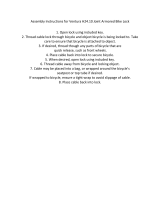
Upper Cable
1. First connect the barrel end of the upper cable to the rear brake
lever. Make sure the long cable casing is on top of the short
cable casing; otherwise, the upper cable will have a twist in it.
2. Route the upper cable through the handlebars (below the
crossbar) with the short cable casing on the same side as the
rear brake lever.
3. Connect the upper cable to the upper plate by passing the
football ends of the upper cable through the threaded holes in the
upper plate and connecting them to the bearing.
4. Screw the adjusting barrels into the upper plate. Don’t tighten
the locknut at this time.
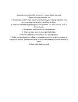
Lower Cable
1. Slide the cable casing through the cable guide on the frame.
2. Connect the lower cable to the lower plate by passing the football
ends of the lower cable through the threaded holes in the lower
plate and connecting them to the bearing.
3. Screw the adjusting barrels into the lower plate. Don’t tighten the
locknut at this time.
4. Connect the lower cable to the rear brake. Don’t adjust the rear
brake at this time. Check to make sure all 11 cable casing ends
on the upper and lower cables are seated correctly, and that the
spring tension of the rear brake is pulling the bearing down.
Adjustment
1. Screw the cable adjusters on the rear brake lever and the upper
cable splitter all the way in.
2. Screw the adjusting barrels in the upper plate in (or out) to set
the bearing for maximum travel. The bearing should be as
far down as it can go without resting on the lower plate or the
adjusting barrels screwed into the lower plate.
3. Use the adjusting barrels that are screwed into the upper plate
to make the bearing parallel to the upper plate. Use a 10mm
wrench to tighten the locknut on the left adjusting barrel of the
upper cable. Leave the right adjusting barrel loose.
4. Screw the lower cable-adjusting barrel into (or out of) the lower
plate until they are as close to the bearing as they can get
without touching it.
5. Screw the cable adjuster on the upper cable splitter out until all
slack is removed from the upper cable. Then screw the cable
adjuster out one more turn to raise the bearing an additional
1mm away from the lower cable adjusting barrels.
CAUTION: Don’t screw the cable adjuster on the upper cable
splitter out more than 8mm. Use the cable adjuster on the rear
brake lever if more adjustment is needed.
6. Check for bearing flop by placing the handlebars in the normal
riding position; then quickly rotate the handlebars back and forth.
Perform the following steps to eliminate bearing flop. NOTE: The
bearing should never be allowed to rest on the lower plate or
lower cable adjusting barrels.
a. Screw the lower cable adjusting barrels out of (or into) the
lower plate until all of the bearing flop is eliminated.
b. Tighten the locknut of the right adjusting barrel on the lower
cable.
c. Rotate the handlebars 180 degrees and recheck for bearing
flop. If there is any bearing flop, use the “loose” adjusting barrels
on the upper and lower cable to remove it.
d. Repeat steps (6a) and (6c) until the handlebars can be rotated
360 degrees without any bearing flop.
7. Finish adjusting the rear brakes.