Page is loading ...

CORRECT FITTING - MAKE
SURE YOUR HELMET COVERS
YOUR FOREHEAD.
INCORRECT FITTING. FOREHEAD
IS EXPOSED AND VULNERABLE
TO SERIOUS INJURY.
ALWAYS WEAR A PROPERLY
FITTED HELMET WHEN
YOU RIDE YOUR SCOOTER.
DO NOT RIDE AT NIGHT.
AVOID RIDING IN WET
CONDITIONS.
HELMETS
SAVE
LIVES !!!

Please Retain your Sales Receipt
as Proof of Purchase.
Notes: _______________________________________________________________
_______________________________________________________________________
_______________________________________________________________________
_______________________________________________________________________
_______________________________________________________________________
_______________________________________________________________________
_______________________________________________________________________
_______________________________________________________________________

The following manual is only a guide to assist you and is not a complete or comprehensive manual of all aspects of
maintaining and repairing your scooter. The scooter you have purchased is a complex object. We recommend that you
consult a professional bicycle dealer if you have doubts or concerns as to your experience or ability to properly assemble,
repair, or maintain your scooter. You will save time and the inconvenience of having to go back to the store if you choose
to write or call us concerning missing parts, service questions, operating advice, and/or assembly questions.
SERVICE
CALL TOLL FREE 1.800.626.2811
Monday - Friday 8:00 a.m. to 5:00 p.m. Central Time
PACIFIC CYCLE, INC.
4902 Hammersley Road
Madison, WI 53711
Customer Service 1.800.626.2811
www.pacific-cycle.com
Serial number is located
on the bottom of the frame
behind the kickstand.

D I R E C T O RY
PART 1
PART 2
PART 3
PART 4
PART 5
PART 7
Parts Identification ...................................................... 01-03
Before You Ride ............................................................04-11
Assembly ..................................................................... 12-29
Servicing ...................................................................... 30-32
Detailed Maintenance .................................................. 33-45
Purchase Record and Warranty ................................. 51-52
Warning / Important
Take notice of this symbol throughout this manual and pay particular
attention to the instructions blocked off and preceded by this symbol.
PART 6
How Things Work ........................................................ 46-50
PACIFIC CYCLE
P.O. Box 344 • 4730 E. Radio Tower Ln. • Olney, IL 62450
Customer Service 1.800.626.2811 • www.pacific-cycle.com
?

02
Your new scooter was assembled and tuned in the factory and then partially disassembled for shipping.
You may have purchased the scooter already fully assembled and ready to ride OR in the shipping carton in
the partially disassembled form. The following instructions will enable you to prepare your scooter for years
of enjoyable scooter riding. For more details on inspection, lubrication, maintenance and adjustment of any
area please refer to the relevant sections in this manual. If you have questions about your ability to properly
assemble this unit, please consult a qualified specialist before riding. If you need replacement parts or have
questions pertaining to assembly of your scooter, call the service line direct at:
SERVICE AND TECHNICAL SUPPORT:
1.800.626.2811
Monday - Friday 8:00 a.m. - 5:00 p.m. Central Time.
Tools Required:
• Phillips head screw driver
• 4mm, 5mm 6mm & 8mm Allen keys
• Adjustable wrench or a 9mm, 10mm,
14mm & 15mm open and box end wrenches
• A pair of pliers with cable cutting ability
To avoid injury, this product must be properly assembled before use. If your scooter was
obtained assembled, we strongly recommend that you review the complete assembly
instructions and perform checks specified in this manual before riding.
01
SCHWINN STINGRAY SCOOTER BASIC PARTS BREAKDOWN
Brake Lever
Upper Fork Crown
Lower Fork Crown
Fork Leg
Front Fender
Front Wheel
Grips
Handlebar
Stem
Rear Fender
Frame
Deck
Kickstand
Rear Wheel

04
PART 2 - BEFORE YOU RIDE
03
ABOUT THIS MANUAL
It is important for you to understand your new scooter. By reading this manual before you go out on your first ride, you’ll know how
to get better performance, comfort, and enjoyment from your new scooter.
It is also important that your first ride on your new scooter is taken in a controlled environment, away from cars, obstacles,
and other cyclists.
GENERAL WARNING
Scooter riding can be a hazardous activity even under the best of circumstances. Proper maintenance of your scooter is your responsi-
bility as it helps reduce the risk of injury. This manual contains many “Warnings” and “Cautions” concerning the consequences of failure
to maintain or inspect your scooter. Many of the warnings and cautions say “you may lose control and fall.” Because any fall can result
in serious injury or even death, we do not repeat the warning of possible injury or death whenever the risk of falling is mentioned.
A SPECIAL NOTE FOR PARENTS
It is a tragic fact that most scooter accidents involve children. As a parent or guardian, you bear the responsibility for the activities and
safety of your minor child. Among these responsibilities are to make sure that the scooter which your child is riding is properly fitted
to the child; that it is in good repair and safe operating condition; that you and your child have learned, understand and obey not only
the applicable local motor vehicle, scooter, and traffic laws, but also the common sense rules of safe and responsible scooter riding.
As a parent, you should read this manual before letting your child ride the scooter. Please make sure that your child always wears an
approved bicycle helmet when riding.
Age/Weight Range
Age
6 years to adult
Weight
Up to 200 lbs.
Handlebar Height
Maximum comfort is usually obtained when the handlebar height is
equal to the height of the seat. You may wish to try different heights
to find the most comfortable position.
Stem Wedge Bolt
Maximum Height/
Minimum Insertion
Mark
Handlebar Binder Bolt
Exceeds 2 1/2”
(64mm)
Threadless headsets and clamp-on stems are not adjustable. Please refer to page 14
for instructions on installation.
The stem’s “Minimum Insertion” mark must not be visible above the top of the headset.
If the stem is extended beyond this mark, the stem may break or damage the fork’s
steerer tube, which could cause you to lose control and fall.
Failure to properly tighten the stem binder bolt, the handlebar binder bolt, or the bar
end extension clamping bolts may compromise steering action, which could cause you
to lose control and fall. Place the front wheel of the scooter between your legs and
attempt to twist the handlebar/stem assembly using a reasonable amount of force. If
you can twist the stem in relation to the front wheel, turn the handlebars in relation to
the stem, or turn the bar end extensions in relation to the handlebar, you must tighten
the appropriate bolts accordingly.

06
05
SAFETY CHECKLIST
Before every ride, it is important to carry out the following safety checks:
1. Brakes
- Ensure front and rear brakes work properly.
- Ensure brake shoe pads are not over worn and are correctly positioned in relation to the rims.
- Ensure brake control cables are lubricated, correctly adjusted and display no obvious wear.
- Ensure brake control levers are lubricated and tightly secured to the handlebar.
2. Wheels and Tires
- Ensure tires are inflated to within the recommended limit as displayed on the tire sidewall.
- Ensure tires have tread and have no bulges or excessive wear.
- Ensure rims run true and have no obvious wobbles or kinks.
- Ensure all wheel spokes are tight and not broken.
- Check that axle nuts are tight. If your scooter is fitted with quick release axles,
make sure locking levers are correctly tensioned and in the closed position.
3. Steering
- Ensure handlebar and stem are correctly adjusted and tightened, and allow proper steering.
- Ensure that the handlebars are set correctly in relation to the forks and the direction of travel.
- Check that the headset locking mechanism is properly adjusted and tightened.
- If the scooter is fitted with handlebar end extensions, ensure they are properly positioned and tightened.
4. Bearings
- Ensure all bearings are lubricated, run freely and display no excess movement, grinding or rattling.
- Check headset, wheel bearings, pedal bearings and bottom bracket bearings.
Helmets
It is strongly advised that a properly fitting, ANSI or SNELL approved,
bicycle safety helmet be worn at all times when riding your scooter.
The correct helmet should:
- be comfortable
- be lightweight
- have good ventilation
- fit correctly
- cover forehead
Always wear a properly fitted helmet which covers the forehead when riding a scooter. Many states
require specific safety devices. It is your responsibility to familiarize yourself with the laws of the state
where you ride and to comply with all applicable laws, including properly equipping yourself and your
scooter as the law requires. Reflectors are important safety devices which are designed as an integral
part of your scooter.
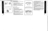
FRONT REFLECTOR ASSEMBLY
Locate front reflector brackets and screws in the parts box.
Assemble clear front reflector to lower fork crown using
(2) screws provided. Face reflector forward and tighten
(2) screws securely. Reflector bracket should be +/- 3
degrees from vertical (90 degrees).
1.
2.

RIDING SAFELY
Scooters are intended for sidewalk riding, and should not be ridden in streets, parking lots
or anywhere that motor vehicles are present. Please consult your local traffic laws for more
information. These safety guidelines are included for your re
ference.
General Rules
When riding obey the same road laws as all other road vehicles, including giving way to
pedestrians, and stopping at red lights and stop signs.
For further information, contact the Road Traffic Authority in your State.
Ride predictably and in a straight line. Never ride against traffic.
Ride defensively. To other road users, you may be hard to see.
Concentrate on the path ahead. Avoid pot holes, gravel, wet road markings, oil, curbs, speed
bumps, drain grates and other obstacles.
Cross train tracks at a 90 degree angle or walk your scooter across.
Expect the unexpected such as opening car doors or cars backing out of concealed driveways.
Be extra careful at intersections and when preparing to pass other vehicles.
Familiarize yourself with all the scooter's features. Practice braking.
Don't carry packages or passengers that will interfere with your visibility or control of the scooter.
Don't use items that may restrict your hearing.
Do not lock up the brakes.
Maintain a comfortable stopping distance from all other riders, vehicles and objects.
Safe braking distances and forces are subject to the prevailing weather conditions.
Wet Weather
IT IS RECOMMENDED TO NOT RIDE IN WET WEATHER
- In wet weather you need to take extra care.
- Brake earlier, you will take a longer distance to stop.
- Decrease your riding speed, avoid sudden braking and take corners with
additional caution.
- Be more visible on the road.
- Wear reflective clothing and use safety lights.
- Pot holes and slippery surfaces such as line markings and train tracks all become
more hazardous when wet.
Night Riding
- Ensure scooter is equipped with a full set of correctly positioned and clean reflectors.
- Refer to page 6 of this manual.
- Use a properly functioning lighting set comprising of a white front lamp and a red rear lamp.
- If using battery powered lights, make sure batteries are well charged.
- Some rear lights available have a flashing mechanism which enhances visibility.
- Wear reflective and light colored clothing.
- Ride at night only if necessary. Slow down and use familiar roads with street lighting, if possible.
IT IS RECOMMENDED TO NOT RIDE AT NIGHT
07
08

10
Avoid streets and surfaces with water, sand, gravel, dirt, leaves, and other debris.
Wet weather impairs traction,braking, and visibility.
Do not ride at night.
Brake will get hot from continuous use. Do not touch after braking.
Avoid excessive speed associated with downhill rides.
Adults must assist children in the initial adjustment procedures to unfold scooter,
adjust handlebar and steering to height, and finally to fold scooter.
Obey all local traffic and scooter riding laws and regulations.
Watch out for pedestrians.
Check and secure all fasteners before every ride.
Replace worn or broken parts immediately.
SCOOTER CARE
Security
It is advisable that the following steps be taken to prepare for and help prevent possible theft.
1. Maintain a record of the scooter’s serial number, located on the bottom
of the frame behind the kickstand.
2. Register the scooter with the local police.
3. Invest in a high quality scooter lock that will resist hack saws and bolt cutters.
Always lock your scooter to an immovable object if it is left unattended.
Cornering Technique
Brake slightly before cornering and prepare to lean your body into the corner.
Please refer to pages 47-48 for braking techniques
.
Rules for Children
To avoid accidents, teach children good riding skills with an emphasis on safety from an early age.
Children should be supervised by an adult.
1. Always wear a properly fitted helmet.
2. Do not play in driveways or the road.
3. Do not ride on busy streets.
4. Do not ride at night.
5. Obey all the traffic laws, especially stop signs and red lights.
6. Be aware of other road vehicles behind and nearby.
7. Before entering a street: Stop, look right, left, and right again for traffic. If there's no traffic, proceed into the roadway.
8. If riding downhill, be extra careful. Slow down using the brakes and maintain control of the steering.
9. Never take your hands off the handlebars
.
09
The Consumer Protection Safety Commission advises that the riding of small wheel diameter
scooters at excessive speeds can lead to instability and is not recommended.
Children should be made aware of all possible riding hazards and correct riding behavior before they take to the streets.
- Do not leave it up to trial and error.
Always wear safety equipment such as helmet, knee pads and elbow pads. Always wear a helmet when riding your scooter
and keep the chinstrap securely buckled. Always wear shoes.
Ride on smooth, paved surfaces away from motor vehicles.
Avoid sharp bumps, drainage grates, and sudden surface changes. Scooter may suddenly stop.

12
Stingray Scooter Fork Assembly
Step #1
Insert one fork leg through the lower crown, and slide it up until it contacts the bolt in the upper crown. Push the leg
up to remove the red stop sign decal from the fork leg. Using a 5mm hex (Allen) wrench align the upper crown bolt
with the fork leg, and tighten upper crown bolt completely into the fork leg. Repeat for other fork leg.
PART 3 - ASSEMBLY
Basic Maintenance
The following procedures will help you maintain your scooter for years of enjoyable riding.
For painted frames, dust the surface and remove any loose dirt with a dry cloth. To clean, wipe with a damp cloth
soaked in a mild detergent mixture. Dry with a cloth and polish with car or furniture wax. Use soap and water to clean
plastic parts and rubber tires. Chrome plated bikes should be wiped over with a rust preventative fluid.
Store your scooter under shelter. Avoid leaving it in the rain or exposed to corrosive materials. Riding on the beach or
in coastal areas exposes your scooter to salt which is very corrosive. Wash your scooter frequently and wipe or spray
all unpainted parts with an anti-rust treatment. Make sure wheel rims are dry so braking performance is not affected.
After rain, dry your scooter and apply anti-rust treatment.
If the hub and bottom bracket bearings of your scooter have been submerged in water, they should be taken out and
re-greased. This will prevent accelerated bearing deterioration.
If paint has become scratched or chipped to the metal, use touch up paint to prevent rust. Clear nail polish can also
be used as a preventative measure.
Regularly clean and lubricate all moving parts, tighten components and make adjustments as required. (Refer to
Parts 4 and 5 of this manual for further details). The use of alloy components and BED, SATIN and TITANIUM surface
treatments minimizes the number of places where rust can surface.
Storage
Keep your scooter in a dry location away from the weather and the sun. Ultraviolet rays may cause paint to fade or
rubber and plastic parts to crack. Before storing your scooter for a long period of time, clean and lubricate all compo-
nents and wax the frame. Deflate the tires to half pressure and hang the scooter off the ground. Don't store near
electric motors as ozone emissions may effect the rubber and paint. Don't cover with plastic as "sweating” will result
which may cause rusting. Please notice that your scooter warranty does not cover paint damage, rust, corrosion, dry
rot or theft.
Step #
2
Align the two fork legs so that the axle dropouts
face forward. Install front wheel, making sure that
the step washers seat into the fork dropouts as
you tighten the axle nuts. Tighten front axle nuts
completely using 15mm wrench.
Upper Fork Crown
Lower Fork Crown
Fork Leg
Remove Decal
12
11

14
13
Tightening/Preloading Aheadset
Stem Installation
(Should be assembled on the bike already)
1. Insert the compression bolt through the top
cap and the stem. Begin threading into the
star nut.
2.Tighten compression bolt so it removes all
play from the fork, but allows the fork to rotate
smoothly.
3. Align the stem with the front wheel. Tighten
the stem clamp bolts to secure the stem to the
steerer tube.
Handlebar Installation
1. Remove the stem cap bolts and stem cap.
2. Insert handlebar into the stem cap.
3. Tighten the stem cap bolts equally. Note
the distance between the stem and stem cap:
It should be equal on the top and bottom of the
stem cap.
A must be equal distance.
Installed
by
factory
Compression Bolt
Top Cap
Stem Clamp Bolts
Spacer
Headset Wedge
Bearing Race
Bearing Dust Cover
Bearing Retainer
Star Nut
(Inside Steerer Tube)
Upper Headset Cup
Headtube
Lower Headset Cup
Bearing Retainer
Bearing Dust Cover
Headset Crown Race
fork
Steerer Tube
Handlebar
Stem Cap
Bolts
Stem Cap
Stingray Scooter Front
Fender Assembly
After the first fork leg is installed:
1. Assemble front fender to fork l
eg and hand
tighten bolt. When installing second fork leg,
remove fender mounting bolt first, assemble
fork leg, and re-install fender mounting bolt.
Hand tighten.
At the end of fork assembly:
2. After fork and front wheel
are completely
assembled, center fender and tighten both
mounting bolts securely.
Step #3
Using 5mm hex (Allen) wrench, tighten the two
lower fork crown pinch bolts completely. Please
note that these bolts should be tightened until the
fork is secure only,
DO NOT OVER TIGHTEN,
or damage to the lower fork crown may occur.
1.
2.

16
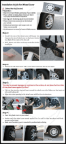
Band Brake Series Installation
Step 1
Assemble the inner drum clockwise onto
the rear hub. Make sure the re-entrant side
is fixed toward you.
Step 2
Assemble the outer shell onto the hub axle
covering inner drum and fasten the nut.
Step 3
Thread inner wire through the adjuster-
screw then connect and fix its end on the
brake pad control lever.
Step 4
Finely adjust the adjuster-screw to reach
the perfect braking performance.
Note:
1. Lubricating the drum can cause faulty braking.
2. Brake pad will wear over time. Turn adjusting barrel to compensate
for pad wear. Replace brake pad before it is completely worn.
Hub
Inner Drum
Clockwise
Outer Shell
Pad Control Lever
Fixing Nut
Inner Wire
Adjuster Screws
15
If the stem is not inserted into the top nut to at least the “Mini-
mum Insertion” mark, it is possible to over-tighten the stem
bolt and damage the fork steerer tube. If these instructions are
not followed, it could cause an unsafe condition and risk injury
to the rider. Check steering tightness prior to riding by strad
-
dling the front wheel. Try turning the handlebar. If you can
turn it without turning the front wheel, the stem is too loose.
Re-align the handlebar with the front wheel and re-tighten the
stem bolt.
Sunken Stem Bolt System
1. Remove the protective shipping cap from the stem wedge.
2. Remove the Stem Plug from the stem. Loosen the Stem Bolt
with a 6mm allen wrench.
3. Insert the stem into the headtube of the scooter. Ensure that
the Minimum Insertion Line is below the top nut of the headset.
4. Align the stem and handlebar so it is in line with the front wheel.
5. Tighten the Stem Bolt with the 6mm allen wrench. Reinsert the
Stem Plug into the stem.
WARNING: MINIMUM INSERTION LINE MUST BE HIDDEN WITHIN
THE HEADTUBE OF THE SCOOTER.

18
While holding the shoe against the
rim, tighten the shoe fixing nut.
3.
Adjust the balance with the spring
tension adjustment screws.
5.
Depress the brake lever about 10 times as
far as the grip to check that everything is
operating correctly and that the shoe
clearance is correct before using the brakes.
6.
Pass the inner cable through the inner
cable lead. Set the cable with a clear
ance
of 1mm between each brake pad and the
rim, tighten the cable fixing bolt.
4.
5 mm Allen key
5 mm Allen key
1mm 1mm
1mm
Spring tension
adjustment screw
Spring tension
adjustment screw
Depress about
10 times
1 mm 1 mm
shoe fixing nut
17
V - Brake
If fitted with V-Brakes, insert the brake
body into the center spring hole in the frame
mounting boss, and then secure the brake
body to the frame with the link fixing bolt.
1.
While holding the shoe against the rim, adjust the
amount of shoe protrusion by interchanging the
position of the B washers (i.e. 6 mm and 3 mm) so
that dimension A is kept at 39 mm or more.
2.
5 mm Allen key
Washer
Link
fixing
bolt
Stopper pin
Spring
hole
39 mm or more
A
3 mm washer B 6 mm washer B
Washer A
Shoe fixing link
Washer A
Washer
Shoe fixing nut

20
Check your Brakes
Press each brake lever to make sure that there is no binding and that the brake pads press hard enough on the rims
to stop the bike. The brake pads should be adjusted so they are 1 mm to 2 mm away from the rim when the brakes
are not applied. Brake pads should be centered on the rim and “toed-in” so the rear portion of each brake pad is about
0.5 - 1.0 mm farther from the rim than the front portion of the brake pad.
Do not ride the scooter until the brakes are functioning
properly. To test, apply the brakes while trying to push
the bike forward to make sure they will stop the scooter.
Never ride a scooter that is not functioning properly.
Do not lock up brakes. Sudden or excessive application
of the front brake may pitch the rider over the handlebars,
causing serious injury or death. When braking, always
apply the rear brake first, then the front.
Brake pad aligned with the rim surface Pad and rim should be parallel.
Direction of rim
rotation
0.5 - 1.0 mm
1- 2 mm
19
V-Style Brakes
If not already assembled, take the brake noodle from the parts box
and slide the cable through the larger opening. The cable housing
will then seat into the end of the noodle. Slide the cable through the
cable lead on the end of the left brake arm, this will cause the noodle
to fit into the lead. Slip the brake cable boot over the cable and posi
-
tion it between both brake arms. Next, loosen the 5mm anchor bolt
at the end of the right brake arm and slide the cable under the retain
-
ing washer. Pull the slack out of the cable making sure a distance of
39mm or more remains between the end of the lead and the start of
the anchor bolt. Once the cable is secured to the brake arms, engage
the brake lever several times, checking the position of the brake
shoes at the rim. The brake shoes should be 1mm away from the
rim when in a relaxed position. When the brake lever is engaged, the
brake shoe should hit the rim flush (never the tire) with the front brake
pad touching the rim slightly before the rear. This is called “toeing-in”
your brake shoe. If this position is not achieved, adjustments to the
brake shoe are required. Loosen the brake shoe hardware and reposi
-
tion the brake shoe. It may take several shoe and cable adjustments
before the required position is accomplished.
Brake
Noodle
Outer
Cable
Lead
Brake
Cable
Boot
Anchor
Bolt
Brake
Arm
Tension
Screw
Brake
Shoe
Pivot
Bolt

22
Fork Leg
Brake Cable
Housing
Rotating
Rod
Cable Boot
with Spring
inside
Cable Anchor
Bolt
Caliper
Body
Actuating
Arm
Caliper Mounting
Bolts with spacers
Quick Release
lever
Fork Drop Out
Disc
Disc Mounting
Bolts
Hub
Centering Bolt
Centering Bolt (inside)
These brakes require breaking in! Ride and use the brakes gently for 13
miles before using the brakes in downhill conditions, for sudden stops,
or any other serious braking. Please be aware that your brake system will
change in performance throughout the wear-in process. The disc brake
should be cleaned before the first ride using rubbing alcohol. NEVER use oil
or similar products to clean your disc brake system.
21
Disc Brakes
If fitted with a front disc brake, the components should already
be attached. However, please check all connections before
attempting to ride the scooter. Secure tightly the 6 bolts that
hold the disc to the front wheel hub and the 2 bolts that hold
the brake mechanism to the fork. Insert the front wheel into the
fork dropouts ensuring that the disc fits into the brake mecha
-
nism between the enclosed brake pads. Secure the front wheel
to the scooter by tightening the quick release mechanism and
clamping the lever to the closed position. Please refer to
section 6 for further instruction on quick release mechanisms.
Next, attach the cable to the brake lever by inserting the cable
end into the cable end holder after the barrel adjuster and lock
nut slots have been aligned with the cable end holder. After
the cable is secured to the lever, rotate the barrel adjuster and
lock nut so the slots no longer line up. Ensure the cable hous
-
ing seats appropriately into the end of the barrel adjuster and
check for any kinks or damage.
Slide the exposed brake cable through the rotating rod located
on the caliper body and seat the housing into the same stop.
Insert the cable into the spring and spring boot.
Next, slide the cable through the cable anchor and pull all the
slack out. Secure the cable in place by tightening the bolts that
comprise the anchor assembly. Some disc brakes will have a
centering devise while others are a free-floating mechanism.
If your caliper body is equipped with centering bolts, apply the
brake lever after the cable has been connected. While engag
ing
the lever, tighten the centering bolts securely. This will center
the caliper body on the disc.
Brake Pads
“C” Clip
Actuating Arm
Rotating Rod
Cable Anchor
Bolt
Caliper
Mounting
Bolt with
spacers
Caliper
Mounting
Bolt with
spacers
Barrel Adjuster
Brake Cable
Housing
Cable
Insertion
Slot
Brake Cable
Cable End
Holder
Brake Type
Selector
Brake Lever
DISC GETS HOT! Severe injury could result from
contact with the hot disc! Mind your legs, as well
as your hands.
Lock Nut

24
SCOOTER
Handlebars
Remove the protective cap from the stem wedge and loosen the stem
bolt using the 6mm Allen key. Some models may use a 13mm
hexagonal bolt instead of an Allen key bolt. Place the handlebar stem
into the head tube, observing the minimum insertion mark on the
handlebar stem and ensuring that all cables are free of tangles. Check
that the fork and the handlebar are facing forward, and that they are
properly aligned with the front wheel. Tighten the stem bolt. Rotate the
handlebar to the desired position. Tighten stem cap bolt 1 (see picture)
two turns, tighten stem cap bolt 2 two turns and so on. Repeat until
handle bar is secure to the stem. See picture for a 4 or 6-bolt system.
Also check that the stem binder bolts are tightened equally and securely.
The handlebar must be inserted so that the minimum insertion
mark cannot be seen.
WARNING: Over tightening the stem
bolt or headset assembly may cause damage to the scooter and/
or injury to the rider.
Stem
Bolt
Minimum
Insertion Mark
Head
Tube
Foreword: Assembling a scooter is an important responsibility. Proper assembly not only gives the rider more enjoyment
of the scooter; it also offers an important measure of safety.
Stem Cap Binder Bolts
Stem Wedge
four bolt
face plate
six bolt face plate
Four Bolt
Face
Plate
Six Bolt
Face
Plate
Getting Started
Open the carton from the top and remove the scooter. Remove the straps and protective wrapping from the scooter.
Inspect the scooter and all accessories and parts for possible shortages. It is recom
mended that the threads and all moving
parts in the parts package be lubricated prior to installation. Do not discard packing materials until assembly is complete
to insure that no required parts are accidentally discarded. Assemble your scooter following the steps that pertain to
your model.
Note: Your scooter may be equipped with different style components than the ones illustrated.
23
Final Check
- If you encounter any problems, refer to the appropriate section
and make any necessary adjustments.
- Check the tire pressure and inflate each tube to the recom
mended
psi as stated on the sidewall of the tire.
- Check that the kickstand operates smoothly and the
kickstand bolt is secured tightly.
- Finally, examine the scooter. Make sure all accessories are
attached and all quick releases, nuts and bolts have been
tightened securely.
- Correct maintenance of your scooter will ensure many years
of happy riding. Service your scooter regularly by referring
to the relevant sections of this manual, OR take it to a
professional bicycle shop.
Remember: Always wear a helmet and obey all
traffic laws.
Never inflate a tire beyond the maximum
pressure marked on the tire’s sidewall.
Exceeding the recommended pressure
may blow the tire off the rim, which
could cause damage to the scooter and
injury to the rider and bystanders.
Tighten both rear wheel axle nuts or the
quick release mechanism securely. Failure
to do this may cause the rear wheel to
dislodge from the frame dropouts resulting
in serious damage or injury.

26
Rotors
Some freestyle BMX bicycles come equipped with a detan
gler
system that will allow the handlebar to spin 360-degrees without
binding the cables. It is very important that this system is adjusted
correctly. Installation should only be done by a qualified scooter
mechanic with the correct tools.
Upper Cable
1. First connect the barrel end of the upper cable to the
rear brake lever. Make sure the long cable casing is on
top of the short cable casing; otherwise, the upper cable
will have a twist in it.
2. Route the upper cable through the handlebars (below
the crossbar) with the short cable casing on the same
side as the rear brake lever.
3. Connect the upper cable to the upper plate by passing
the football ends of the upper cable through the threaded
holes in the upper plate and connecting them to the bearing.
4. Screw the adjusting barrels into the upper plate. Don’t
tighten the locknuts at this time.
Lower Cable
1. Slide the cable casing through the cable guide on the frame.
2. Connect the lower cable to the lower plate by passing
the football ends of the lower cable through the threaded
holes in the lower plate and connecting them to the bearing.
3. Screw the adjusting barrels into the lower plate. Don’t
tighten the locknuts at this time.
4. Connect the lower cable to the rear brake. Don’t adjust
the rear brake at this time.
NOTE: Check to make sure all 11 cable casing ends on
the upper and lower cables are seated correctly, and that
the spring tension of the rear brake is pulling the bearing down.
Adjustment
1. Screw the cable adjusters on the rear brake lever and the
upper cable splitter all the way in.
2. Screw the adjusting barrels in the upper plate in (or out)
to set the bearing for maximum travel. The bearing should
be as far down as it can go without resting on the lower
plate or the adjusting barrels screwed into the lower plate.
3. Use the adjusting barrels that are screwed into the
upper plate to make the bearing parallel to the upper
plate. Use a 10mm wrench to tighten the locknut on the
left adjusting barrel of the upper cable. Leave the right
adjusting barrel loose.
4. Screw the lower cable adjusting barrel into (or out of)
the lower plate until they are as close to the bearing as
they can get without touching it.
5. Screw the cable adjuster on the upper cable splitter out
until all slack is removed from the upper cable. Then
screw the cable adjuster out one more turn to raise the
bearing an additional 1mm away from the lower cable
adjusting barrels.
CAUTION: Don’t screw the cable adjuster on the upper
cable splitter out more than 8mm. Use the cable adjuster
on the rear brake lever if more adjustment is needed.
6. Check for bearing flop by placing the handlebars in the
normal riding position, then quickly rotate the handlebars
back and forth. Perform the following steps to eliminate
bearing flop.
NOTE: The bearing should never be allowed to rest on
the lower plate or lower cable adjusting barrels.
a) Screw the lower cable adjusting barrels out of (or
into) the lower plate until all bearing flop is eliminated.
b) Tighten the locknut of the right adjusting barrel on the
lower cable.
c) Rotate the handlebars 180 degrees and recheck
for bearing flop. If there is any bearing flop, use the
“loose” adjusting barrels on the upper and lower cable to
remove it.
d) Repeat steps (6a) and (6c) until the handlebars can be
rotated 360 degrees without any bearing flop.
7. Finish adjusting the rear brakes.
25
Front Wheel
1. Make sure the brakes are loose enough to allow the wheel to
pass through the brake pads easily.
2. Place wheel into fork drop outs.
3. Install retaining washers with raised lip pointed towards the fork,
and insert into the small hole of the fork blade.
NOTE: Some scooters may have step retaining washers in place
of the retaining washer (shown in dotted box). If so, install the
step retaining washer, raised portion sliding in to the fork dropouts.
4. Install axle nut and tighten.
Make sure the wheel is centered between the fork blades.
5. Spin the wheel to make sure that it is centered and clears the
brake shoes. Tighten the brakes if necessary.
6. Turn the scooter upright using the kickstand to support it.
It is very important to check the front wheel
connection to the scooter. Failure to properly tight
en
may cause the front wheel to dislodge.
Axle Nut
Axle
Hub
Cone Nuts
Fork Drop Out
Retaining
Washer
Step
Retaining
Washer

28
Axle Peg Assembly Instructions
Non-Threaded
First remove the axle nut from the wheel. There will be either
a retaining washer or a step retaining washer included. Place
this washer between the peg and the frame of the scooter. Slide
the peg onto the axle, followed by a flat washer and lastly the
axle nut. Tighten the axle nut clockwise until the peg fits snugly
against the frame or fork. Repeat for all the remaining pegs.
Non-Threaded
Threaded
Threaded
This style of peg is threaded to fit the axle. Make sure the axle
nut is tight with a 15mm wrench. Place a screw driver through
the mounting holes of the peg and attach the peg to the axle by
turning clockwise. Tighten against the frame or fork for a snug
fit. Repeat for all the remaining pegs.
PLEASE NOTE: Not all axles are able to accept axle pegs.
Please consult the Pacific Cycle Service Department if
you have any questions. Some scooters come with two
or four pegs.
27
Failure to adjust correctly may result in
loss of braking power and personal injury.
Barrel End
Single Cable Casing
Cable Adjuster
Cable Splitter
Upper Cable
(short casing)
Upper Cable
(long casing)
Upper Plate
Bearing
Football Ends
Lower Plate
Lower Cable
Adjusting Barrel
Locknut
Keyed Washer
Locknut
Adjusting Barrel
37mm + or - 1mm
Set for Max. Travel
Minimum 1mm (1/32”)

30
PART 4 - SERVICING
Correct routine maintenance of your new bike will ensure:
Smooth running - Longer lasting components - Safer riding - Lower running costs
Every time you ride your scooter, its condition changes. The more you ride, the more frequently maintenance will be
required. We recommend you spend a little time on regular maintenance tasks. The following schedules are a useful guide
and by referring to Part 5 of this manual, you should be able to accomplish most tasks. If you require assistance, we
recommend you see a scooter specialist.
Weekly
Every Six Months
Yearly
brake calipers
brake levers
brake cables
wheel bearings
headset
oil
oil
lithium based grease
lithium based grease
lithium based grease
3 drops from oil can
2 drops from oil can
disassemble
disassemble
disassemble
Schedule 1 - Lubrication
Note: The frequency of maintenance should increase with use in wet or dusty conditions. Do not over
lubricate - remove excess lubricant to prevent dirt build up. Never use a degreaser to lubricate your chain (WD-40™)
ComponentFrequency Lubricant
How to Lubricate
29
Final Check
Install any additional parts that are supplied with your bike.
NOTE: Your scooter may be equipped with different style components than the ones illustrated.
Reflectors: Attach the white reflector to the front bracket and the red reflector to the rear bracket using an 8mm
wrench or a Phillips head screwdriver. Attach the brackets to the scooter using the hardware provided. For some models,
the front reflector bracket will be mounted on the front brake assembly bolt that fits through the fork. It is important to
make sure all connections are tightened securely and that the reflectors are properly angled.
Tire Pressure: Check tire pressure, inflate to the range recommended on the tire sidewalls.
Pegs: There are many different types of pegs-too many to deal with individually in this manual.
Please see your dealer for specific information regarding peg installation.
Before riding, ensure all nuts, bolts and fittings
on the scooter have been correctly tightened.

32
Tools Required
1. Open ended wrench or ring
wrenches: 8mm, 9mm, 10mm,
12mm, 13mm, 14mm, 15mm
2. Open end or pedal wrench 15mm
3. Allen key wrenches: 4mm, 5mm,
6mm, 8mm
4. Adjustable wrench
5. Standard flat head screwdriver
6. Standard Phillips head screwdriver
7. Standard slip joint pliers
8. Tire pump
9 Tube repair kit
10. Tire levers
Travel Tools
1. Spare Tube
2. Patch kit
3. Pump
4. Tire levers
5. Multi-tool
6. Change (phone call)
31
Task
Check tire pressure
Check brake operation
Check wheels for loose spokes
Make sure nothing is loose
Quick wipe down with damp cloth
Lubrication as per schedule 1
Lubrication as per schedule 1
Check brake adjustment
Check brake and gear cable adjustment
Check tire wear and pressure
Check wheels are true and spokes tight
Check hub, head set
Check handlebars are tight
Check frame and fork for trueness
Check all nuts and bolts are tight
Lubrication as per schedule 1
Check all points as per monthly service
Check and replace brake pads, if required
Lubrication as per schedule 1
Frequency
Before every ride
After every ride
Weekly
Monthly
Every Six Months
Yearly
Page Reference
34
40-43
33
33
13
30
30
40-43
38
34
33
35, 39
37-38
44
30
31
40-43
30
Schedule 2 - Service Checklist
/