Page is loading ...

Model # MB500
500-POUND CAPACITY
UNIVERSAL MOBILE BASE
bit.ly/wenvideo
Your new tool has been engineered and manufactured to WEN’s highest standards for dependability,
ease of operation, and operator safety. When properly cared for, this product will supply you years
of rugged, trouble-free performance. Pay close attention to the rules for safe operation, warnings,
and cautions. If you use your tool properly and for intended purpose, you will enjoy years of safe,
reliable service.
IMPORTANT:
NEED HELP? CONTACT US!
Have product questions? Need technical support?
Please feel free to contact us at:
800-232-1195
WENPRODUCTS.COM
(M-F 8AM-5PM CST)
WENPRODUCTS.COM
For replacement parts visit

TABLE OF CONTENTS
Technical Data
2
3
4
5
6
9
10
General Safety Rules
Specific Rules For The Mobile Base
TECHNICAL DATA
Model Number:
Maximum Weight Capacity:
Minimum Square Size:
Maximum Square Size
Maximum Rectangle Size:
Assembled Product Weight:
MB500
500 lbs (225 kg)
11.8˝ x 11.8˝ (300 mm x 300 mm)
35.4˝ x 35.4˝ (900 mm x 900 mm)
19.7˝ x 51.2˝ (500 mm x 1300 mm)
15.5 lbs (7 kg)
2
Assembly
Operation
Exploded View and Parts List
Warranty

1. READ and become familiar with this entire instruction manual. LEARN the tool’s applications, limitations, and
possible hazards.
2. AVOID DANGEROUS CONDITIONS. DO NOT use power tools in wet or damp areas or expose them to
rain.
3. DO NOT use power tools in the presence of flammable liquids or gases.
4. ALWAYS keep your work area clean, uncluttered, well lit and well ventilated. DO NOT work on floor surfaces
that are slippery with sawdust or wax.
5. KEEP BYSTANDERS AT A SAFE DISTANCE from the work area, especially when the tool is running.
NEVER allow children or pets near the tool.
6. DRESS FOR SAFETY. DO NOT wear loose clothing, gloves, neckties, or jewelry (rings, watches, etc.) When
operating the tool, inappropriate clothing and items can get caught in moving parts and draw you in. ALWAYS wear
non-slip footwear and tie back long hair.
7. APPROVED SAFETY GLASSES should be worn by the operator and any assistants when using a power tool.
Use ear protection such as plugs or muffs during extended periods of operation.
8. WEAR A FACE MASK OR DUST MASK to fight the dust produced by sanding operations.
Safety is a combination of common sense, staying alert and knowing how your item works.
SAVE THESE SAFETY INSTRUCTIONS.
GENERAL SAFETY RULES
WARNING: To avoid mistakes and serious injury, do not plug
in your tool until the following steps have been read and understood.
WARNING: Dust generated from certain materials can be hazardous to
your health. Always operate the tool in a well-ventilated area and provide
for proper dust removal. Use dust collection systems whenever possible.
9. STAY ALERT. A moments of inattention when operating power tools may result in serious personal injury.
DO NOT use if tired or under the influence of drugs, alcohol or medication.
10. CHECK FOR DAMAGED PARTS. Check for alignment of moving parts, jamming, breakage, improper
mounting, or any other conditions that may affect the tool’s operation. Any part that is damaged should be properly
repaired or replaced before use.
11. DO NOT MODIFY or use the tool to do a job for which it was not designed.
12. NEVER STAND ON A TOOL. Serious injury could result if the tool tips or is accidentally hit. DO NOT store
anything above or near the tool.
13. AVOID ACCIDENTAL START-UPS. Make sure the power switch is in the OFF position before plugging in
the power cord.
3

14. REMOVE ADJUSTMENT TOOLS. Always make sure all adjustment tools are removed from the saw before
turning it on.
15. KEEP GUARDS IN PLACE AND IN WORKING ORDER.
16. DO NOT OVERREACH. Keep proper footing and balance at all times.
17. NEVER LEAVE A RUNNING TOOL UNATTENDED. Turn the power switch to OFF. Do not leave the
tool until it has come to a complete stop.
18. ALWAYS remove the power cord plug from the electrical outlet when making adjustments, changing parts,
cleaning, or working on the tool.
19. MAINTAIN TOOLS PROPERLY. ALWAYS keep tools clean and in good working order. Follow instruc-
tions for lubricating and changing accessories.
20. STORE IDLE EQUIPMENT, preferably in a locked dry cupboard.
GENERAL SAFETY RULES
SPECIFIC RULES FOR THE MOBILE BASE
4
1. Make sure the mobile base is fully assembled according to the instructions before operation.
2. For maximum stability, use the mobile base only on a flat, level surface.
3. Any machine must be bolted securely to the mobile base before use.
4. Do not exceed the maximum weight capacity of 500 lbs.
5. Never use your machine while the mobile base is in the raised (mobile) position. Always lower the machine into
the static position and check for stability before operating.
6. Unplug any electrical tools before moving or repositioning the machine.
7. When moving the machine, always push on the base but not the machine itself to minimize the risk of tipping
the machine over.
8. Always test your setup for stability and safety after repositioning.

EXPLODED VIEW AND PARTS LIST
No. Part No. Description Qty. Step
1 MB500-001 Corner (Back-Left) 1
Step 12 MB500-002 Corner (Back-Right) 1
3 MB500-003 Wheel, 3” 2
4 MB500-004 Corner (Front-Left) 1
Step 2
5 MB500-005 Corner (Front-Right) 1
6 MB500-006 Support Foot 2
7 MB500-007 Swivel Plate 2 Step 3
8 MB500-008 Swivel Caster 2 Step 4
9 MB500-009 Foot Lever 2 Step 5
10 MB500-010 Short Side Rail 4
Step 6
11 MB500-011 Long Side Rail 4
No. Part No. Description Qty. Step
S1 MB500-101 M6x50 Hex Screw 2
Step 1
S2 MB500-102 Wheel Spacer 2
S3 MB500-103 M6 Lock Nut 4 Step 1 & 3
S4 MB500-104 M10 Nut 4 Step 2 & 4
S5 MB500-105 M6x70 Hex Screw 2 Step 3
S6 MB500-106 Caster Lock Washer 2 Step 4
S7 MB500-107 M8x70 Hex Screw 2
Step 5
S8 MB500-108 Lever Spacer 4
S9 MB500-109 Lever Lock Washer 2
S10 MB500-110 M8 Nut 2
S11 MB500-111 M6x12 Hex Screw 24
Step 6
S12 MB500-112 M6 Flanged Nuts 24
3
95678
2
14 1011
S1S11 S12 S2 S3
S3
S9
S4 S8 S10S4 S5
S7
S6
Carefully unpack and identify all the components and hardware according to the exploded view and parts list below.
Prepare for assembly by grouping the parts according their corresponding steps. If any part is missing or damaged,
please call our customer service center at 1-800-232-1195 M-F 8-5 CST.
COMPONENTS: HARDWARE:
5

ASSEMBLY
TOOLS NEEDED (not included):
• Tape measure • 13mm (1/2 in.) wrench
• 10mm (3/8 in.) wrench • 17mm (5/8 in.) wrench
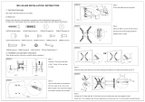
STEP 1: ASSEMBLE THE FIXED WHEELS
Parts Needed: • Two back corner brackets (1 & 2)
• Two wheels (3)
• Two M6x50 hex screws (S1)
• Two wheel spacers (S2)
• Two M6 lock nuts (S3)
• 10mm wrench
From the outside of the corner bracket (1 or 2), insert a M6x50 hex screw
(S1) through the wheel bracket, the wheel (3) and the wheel spacer (S2).
Attach the M6 lock nut (S3) from the inside of the bracket and tighten with
a 10mm wrench.
NOTE: Do not overtighten the nut, as this could pull the screw head
against the mounting bracket and cause the bracket to deform, impeding
the wheel’s function.
Repeat for the other back corner bracket.
STEP 2: ASSEMBLE THE SUPPORT FEET
Parts Needed: • Two front corner brackets (4 & 5)
• Two support feet (6)
• Two M10 nuts (S4)
• 17mm wrench
1. Take a front corner bracket (4 or 5) and screw in the support foot (6)
from the bottom of the foot flange. NOTE: Adjust the height of the rubber
foot so that the foot’s bottom surface is at the same height as the bottom of
the fixed wheels. This will make the base level when resting on the rubber
feet and wheels.
2. Attach the M10 nut (S4) onto the rubber support foot (6). Check that
the foot is set at a suitable height and tighten the M10 nut against the flange
using a 17mm wrench.
Repeat for the other front corner bracket.
WARNING: Do not operate the mobile base until it has been fully assembled according to the instruc-
tions. Follow all warnings to reduce the risk of personal injury or machine damage.
6
Step 1 - 1
Step 2 - 1
Step 2 - 2

ASSEMBLY
STEP 3: ASSEMBLE THE SWIVEL PLATES
Parts Needed: • Two swivel plates (7)
• Two M6x70 hex screws (S5)
• Two M6 lock nuts (S3)
• 10 mm wrench
From the outside of the front corner bracket (4 or 5), insert the M6x70
hex screw (S5) through the lower hole of the caster flange and the swivel
plate (7). Secure with an M6 lock nut (S3) from the other side of the
caster flange and tighten it using a 10mm wrench.
Check that the swivel plate is able to swivel upwards, but not downwards.
STEP 4: ASSEMBLE THE SWIVEL CASTERS
Parts Needed: • Two swivel casters (8)
• Two caster lock washers (S6)
• Two M10 nuts (S4)
• 17mm wrench
From the bottom of the swivel plate (7), insert the swivel caster (8) through
the swivel plate (7) and the caster lock washer (S8). Secure with an M10
flange nut and tighten the nut using a 17mm wrench.
STEP 5: ASSEMBLE THE FOOT LEVERS
Parts Needed: • Two foot levers (9)
• Two M8x70 hex screws (S7)
• Four lever spacers (S8)
• Two lever lock washers (S9)
• Two M8 nuts (S10)
• 13 mm wrench
1. From the outside of the front corner bracket (4 or 5), insert the M8x70
hex screw (S7) through the upper hole of the caster flange, a lever spacer
(S8), the foot lever (9) and another lever spacer (S8). Attach the lever
lock washer (S9) and M10 flanged nut (S10) from the inside of the caster
flange and tighten the nut using a 13mm wrench.
2. Test the mechanism of the foot levers. When the foot lever is de-
pressed, the base will be mobile, resting on the caster wheel. When the
foot lever is raised, the caster wheel will be raised and the base will be
static.
7
Step 3 - 1
Step 4 - 1
Step 5 - 1
Step 5 - 2

ASSEMBLY
STEP 6: ASSEMBLE THE RAILS
Parts Needed: • Four short side rails (10)
• Four long side rails (11)
• Twenty-four M6x12 hex screws (S11)
• Twenty-four M6 flanged nuts (S12)
• 10mm wrench
1. Carefully measure the footprint of the machine that will be placed onto the mobile base. Add about 1 inch to the
dimension to allow clearance for the fasteners. Note that the distance between the holes on the rail is 1 inch, so that
rails can be adjusted in 1-inch increments.
8
Step 6 - 3
Step 6 - 4
NOTE: If it will be difficult to to move your machine from the floor onto
the mobile base, raise it off the floor with four 2x4 blocks and assemble the
base around your machine.
2. Refer to the exploded view on page 5. Position the corners and rails in
the desired dimensions and arrangement. To maximize stability, position
the side rails into the corner brackets as far as is practical.
3. Assemble the side rails to the corner brackets. Each rail must be se-
cured to its corner bracket using two M6x12 hex screws (S11) and two
M6 flanged nuts (S12). Insert the M6x12 hex screw from the outside and
tighten M6 nut from the inside using a 10mm wrench. The fasteners do not
need to be in adjacent holes.
4. Assemble the side rails together. The short rails will slide into the long
rails. Each rail must be secured to its mating rail using two M6x12 hex
screws (S11) and two M6 flanged nuts (S12). Position the fasteners as far
apart as possible to maximize stability. Insert the M6x12 hex screw from
the outside and tighten M6 nut from the inside using a 10mm wrench.
5. Check that all connections are secure. Lift up the foot levers to put the
base in its static configuration, and check that it is level. If needed, you may
need to adjust the support foot height as described in Step 2.

OPERATION
1. Place the fully assembled mobile base on a level surface.
2. Carefully plan the orientation of the machine onto the mobile base. When the mobile base is in the raised posi-
tion, the foot lever side will be lifted 1.2 inches (30 mm) higher that the fixed wheel side. To minimize the risk of
the machine being tipped over, the heaviest weight should be positioned at the foot lever side.
3. Securely bolt the machine onto the mobile base using the mounting holes on the surface of each corner piece.
4. The total weight being placed on the mobile base must not exceed the maximum weight capacity of 500 lbs.
5. Unplug any electrical tools before moving or repositioning the machine.
6. To move the machine, step down on the two foot levers of the mobile base to raise the base into mobile configu-
ration. When moving, always push on the base but not the machine itself to minimize of risk of tipping it over. To
stabilize the machine, lift up the foot levers to lower the base into the static configuration.
9
Mobile Configuration: foot levers depressed, mobile
base resting on the swivel casters.
Static Configuration: foot levers raised, mobile base
resting on the rubber feet.
7. Test the stability in both the mobile configuration (on the casters) and the static configuration (on the rubber feet).
Use extra caution when raising top heavy machines such as drill presses and band saws as they have a higher chance
of being tipped over.
8. Never use your machine while the base is in the mobile configuration. Always lower the machine into the static
configuration check that it is stable before operation.
9. Always test your setup for stability and safety after repositioning.

WEN Products is committed to building tools that are dependable for years. Our warranties are consistent with this
commitment and our dedication to quality.
LIMITED WARRANTY OF WEN CONSUMER POWER TOOLS PRODUCTS FOR HOME USE
GREAT LAKES TECHNOLOGIES, LLC (“Seller”) warrants to the original purchaser only, that all WEN con-
sumer power tools will be free from defects in material or workmanship for a period of two (2) years from date of
purchase. Ninety days for all WEN products, if the tool is used for professional use.
SELLER’S SOLE OBLIGATION AND YOUR EXCLUSIVE REMEDY under this Limited Warranty and,
to the extent permitted by law, any warranty or condition implied by law, shall be the repair or replacement of
parts, without charge, which are defective in material or workmanship and which have not been misused, carelessly
handled, or misrepaired by persons other than Seller or Authorized Service Center. To make a claim under this
Limited Warranty, you must make sure to keep a copy of your proof of purchase that clearly defines the Date of
Purchase (month and year) and the Place of Purchase. Place of purchase must be a direct vendor of Great Lakes
Technologies, LLC. Third party vendors such as garage sales, pawn shops, resale shops, or any other secondhand
merchant void the warranty included with this product. Contact [email protected] or 1-800-232-1195
to make arrangements for repairs and transportation.
When returning a product for warranty service, the shipping charges must be prepaid by the purchaser. The prod-
uct must be shipped in its original container (or an equivalent), properly packed to withstand the hazards of ship-
ment. The product must be fully insured with a copy of the warranty card and/or the proof of purchase enclosed.
There must also be a description of the problem in order to help our repairs department diagnose and fix the issue.
Repairs will be made and the product will be returned and shipped back to the purchaser at no charge.
THIS LIMITED WARRANTY DOES NOT APPLY TO ACCESSORY ITEMS THAT WEAR OUT FROM
REGULAR USAGE OVER TIME INCLUDING BELTS, BRUSHES, BLADES, ETC. ANY IMPLIED WAR-
RANTIES SHALL BE LIMITED IN DURATION TO TWO (2) YEARS FROM DATE OF PURCHASE.
SOME STATES IN THE U.S., SOME CANADIAN PROVINCES DO NOT ALLOW LIMITATIONS ON
HOW LONG AN IMPLIED WARRANTY LASTS, SO THE ABOVE LIMITATION MAY NOT APPLY
TO YOU.
IN NO EVENT SHALL SELLER BE LIABLE FOR ANY INCIDENTAL OR CONSEQUENTIAL DAM-
AGES (INCLUDING BUT NOT LIMITED TO LIABILITY FOR LOSS OF PROFITS) ARISING FROM
THE SALE OR USE OF THIS PRODUCT. SOME STATES IN THE U.S. AND SOME CANADIAN PROV-
INCES DO NOT ALLOW THE EXCLUSION OR LIMITATION OF INCIDENTAL OR CONSEQUEN-
TIAL DAMAGES, SO THE ABOVE LIMITATION OR EXCLUSION MAY NOT APPLY TO YOU.
THIS LIMITED WARRANTY GIVES YOU SPECIFIC LEGAL RIGHTS, AND YOU MAY ALSO HAVE
OTHER RIGHTS WHICH VARY FROM STATE TO STATE IN THE U.S., PROVINCE TO PROVINCE
IN CANADA AND FROM COUNTRY TO COUNTRY.
THIS LIMITED WARRANTY APPLIES ONLY TO PORTABLE ELECTRIC TOOLS, BENCH POWER
TOOLS, OUTDOOR POWER EQUIPMENT AND PNEUMATIC TOOLS SOLD WITHIN THE UNIT-
ED STATES OF AMERICA, CANADA AND THE COMMONWEALTH OF PUERTO RICO. FOR WAR-
RANTY COVERAGE WITHIN OTHER COUNTRIES, CONTACT THE WEN CUSTOMER SUPPORT
LINE.
LIMITED TWO YEAR WARRANTY
10


THANKS FOR REMEMBERING
/