Danfoss VLT Decentral Drive FCD 300 (Legacy Product) User guide

Type
User guide
Rev. 2009-11-26
www.danfoss.com/drives
130R0465 MG90S122
*MG90S122*
Instruction Manual
FCD 300
MAKING MODERN LIVING POSSIBLE
FCD 300 Instruction Manual
MG90S122
Contents
1 The Decentral Concept
1-1
Introduction 1-1
Decentral Design Benefits 1-2
Application Examples 1-10
Product Design Guide 1-13
Ordering Form 1-19
PC Software Tools 1-20
Accessories 1-21
Communication 1-23
Good Installation Practice 1-26
Servicing the Danfoss Decentral Products 1-29
2 Introduction to FCD 300
2-1
Safety 2-2
High Voltage Warning 2-2
These Rules Concern Your Safety 2-2
Warning against Unintended Start 2-2
Technology 2-3
CE Labeling 2-5
3 Installation
3-1
Mechanical Dimensions 3-1
Mechanical Dimensions, Motor Mounting 3-1
Mechanical Dimensions, Stand-alone Mounting 3-1
General Information about Electrical Installation 3-5
Electronics Purchased without Installation Box 3-6
EMC-compliant Electrical Installation 3-8
Grounding of Shielded/Armored Control Cables 3-10
Diagram 3-11
RFI Switches J1, J2 3-11
Electrical Installation 3-12
Location of Terminals 3-12
AC line input connections 3-14
Pre-fuses 3-14
Motor Connection 3-14
Direction of Motor Rotation 3-15
Line Power and Motor Connection with Service Switch 3-15
VLT
®
Decentral FCD 300 Design Guide Contents
MG.90.S1.22 - VLT
®
is a registered Danfoss trademark
Connection of HAN 10E Motor Plug for T73 3-16
Parallel Connection of Motors 3-16
Motor Cables 3-17
Motor Thermal Protection 3-17
Brake Resistor 3-17
Control of Mechanical Brake 3-17
Electrical Installation, Control Cables 3-18
Connection of Sensors to M12 Plugs for T63 and T73 3-19
Electrical Installation, Control Terminals 3-19
PC Communication 3-20
Relay Connection 3-20
Connection Examples 3-21
4 Programming
4-1
LCP Control Unit 4-1
The LCP 2 Control Unit, Option 4-1
Parameter Selection 4-6
Parameter Group 0-** Operation & Display 4-8
Setup Configuration 4-8
Parameter Group 1-** Load and Motor 4-14
DC Braking 4-18
Parameter Group 2-** References & Limits 4-22
Reference Handling 4-23
Reference Function 4-26
Parameter Group 3-** Inputs and Outputs 4-29
Parameter Group 4-** Special Functions 4-36
PID Functions 4-39
Handling of Feedback 4-40
Serial Communication 4-45
Control Word According to FC Protocol 4-50
Status Word According to FC Profile 4-51
Fast I/O FC Profile 4-53
Control Word According to Serial Communication Bus Profile 4-53
Status Word According to Profidrive Protocol 4-55
Parameter Group 5-** Serial communication 4-57
Parameter Group 6-** Technical Functions 4-63
5 All About FCD 300
5-1
Brake Resistors 5-1
Contents VLT
®
Decentral FCD 300 Design Guide
MG.90.S1.22 - VLT
®
is a registered Danfoss trademark
Dynamic Braking 5-1
Internal Brake Resistor 5-6
Special Conditions 5-9
Galvanic Isolation (PELV) 5-9
Ground Leakage Current and RCD Relays 5-9
Extreme Operating Conditions 5-10
dU/dt on Motor 5-11
Switching on the Input 5-11
Acoustic Noise 5-11
Temperature-Dependent Switch Frequency 5-12
Derating for Air Pressure 5-12
Derating for Running at Low Speed 5-12
Motor Cable Lengths 5-12
Vibration and Shock 5-13
Air Humidity 5-13
UL Standard 5-13
Efficiency 5-13
AC Line Supply Interference/Harmonics 5-14
Power Factor 5-14
Emission Test Results according to Generic Standards and PDS Product
Standard 5-14
Immunity Test Result according to Generic Standards, PDS Product Stand-
ards and Basic Standards 5-15
Aggressive Environments 5-16
Cleaning 5-16
Status Messages 5-18
Warnings/Alarm Messages 5-18
Warning Words, Extended Status Words and Alarm Words 5-20
General Technical Data 5-22
Available Literature 5-27
Factory Settings 5-28
6 Index
6-1
VLT
®
Decentral FCD 300 Design Guide Contents
MG.90.S1.22 - VLT
®
is a registered Danfoss trademark
Contents VLT
®
Decentral FCD 300 Design Guide
MG.90.S1.22 - VLT
®
is a registered Danfoss trademark
1 The Decentral Concept
1.1 Introduction
Danfoss was the world's first company to manufacture and supply adjustable frequency drives for infinitely-variable speed control of three-phase AC
motors. Until then, AC motors had to operate at the speed determined by the frequency of the line power supply.
Production of adjustable frequency drives started in 1968. The first adjustable frequency drive was also the first decentralized drive as it was placed next
to the motor.
The first adjustable frequency drive was totally enclosed and filled with silicone oil for cooling, as semiconductors of that time were very inefficient. The
enclosure design was made for mounting the drive directly in the application next to the motor. Temperature, water, cleaning agents, dust and other
environmental factors were also no problem, even in harsh environments.
Semiconductors improved during the next decades. Air-cooling showed sufficient and oil cooling was abandoned. At the same time use of adjustable
frequency drives grew significantly. PLCs gained a footing for advanced application control and it became common practice to install all adjustable
frequency drives in one cabinet, rather than several places in the factory.
Continuing improvements in semiconductors and related technologies - such as serial communication bus technology - now again makes it feasible to
consider installing drives close to the motors, achieving the benefits of decentralized installation without the disadvantages from the first oil-filled ad-
justable frequency drives.
Development of automation in industry is based on the ability to send and receive data from the application needed to control the processes. More and
more sensors are installed and more and more data is submitted to the central PLC control. This trend depends on increased use of serial communication
bus systems.
Industrial sources often claim that up to 30% of all drive installations will be installed decentrally within the next few years, and the trend towards
distributed intelligent control is undisputed as more and more components and applications are developed for decentralized installation.
This book is a general introduction to basic features of decentralized installation philosophies for motor controls and differences from the centralized
concept. It will help you choose the most suitable concept and guide you through the process of selecting the appropriate products.
Finally, we have included comprehensive information about the Danfoss decentralized products.
VLT
®
Decentral FCD 300 Design Guide 1 The Decentral Concept
MG.90.S1.22 - VLT
®
is a registered Danfoss trademark
1-1
1
1.2 Decentral Design Benefits
In the following, we will concentrate on describing decentralized installation of adjustable frequency drives, referred to here as motor controls.
There are two topologic concepts for the layout of motor control installations in a plant, in the following referred to as “centralized” and “decentralized”
installations. The two typologies are illustrated in the figure.
In a centralized installation:
- motor controls are placed in a central place
In a decentralized installation:
- motor controls are distributed throughout the plant, mounted
on or next to the motor they control
Decentralized does not mean
control cabinet free
, but merely that their
enormous size can now be reduced thanks to innovative designs of the
components that will be placed decentralized. There will continue to be
a need for cabinets for power distribution and for overall intelligence, and
there are areas, particularly in the process industry with areas such as
explosion protection, where centralized cabinets continue to be the pre-
ferred solution.
Placing the advanced and reliable electronics needed to ensure a smooth,
responsive and economical operation of the motor next to – or on – the
motor facilitates modularization and reduces cabling costs and EMC prob-
lems dramatically. Further benefits:
Figure 1.1: Centralized versus decentralized installations
Space-consuming motor control cabinets in long rows of centralized panels are eliminated
Reduced efforts for building in and wiring long shielded motor cables where special attention on EMC terminations is required
Heat dissipation from power electronics is moved from the panel into the plant
Standardized machine elements designed as modules reduce design time and time to market
Commissioning is easier and faster
Decentralized motor control is rapidly gaining ground despite of the advantages of the centralized control concept:
no need for extra space around the motor or close to the motor
no control cable wiring into the plant
independence of plant environment
1 The Decentral Concept VLT
®
Decentral FCD 300 Design Guide
1-2
MG.90.S1.22 - VLT
®
is a registered Danfoss trademark
1
1.2.1 Direct Cost Savings
Motor controls for decentralized installations must be built to meet the harsh conditions in manufacturing areas - especially such conditions found in the
food and beverage industry, where frequent wash downs are required. This of course increases the cost of the drive. This increase will be more than off
set by savings in expenses for cabinets and cables.
The cable saving potential is considerable, as will be demonstrated by the following example.
The figure illustrates an installation with motors distributed in a number of rows with several motors in each, as is the situation in for example parallel
bottling or baking lines in the food and beverage industry. This example shows the need for power cables from the centrally placed drives to the motors.
Figure 1.2: Centralized installation
The drives are distributed equidistant with the distance L between each drive and the distance h between each row and also with a distance h from the
centralized power entry/cabinet location to the first row. There are n rows, and N drives in each row.
VLT
®
Decentral FCD 300 Design Guide 1 The Decentral Concept
MG.90.S1.22 - VLT
®
is a registered Danfoss trademark
1-3
1
Figure 1.3: Decentralized installation
The Figure 1.4 shows how the three-phase line cable can be distributed
with power looping from one motor (drive) to the next. The cable saving
potential is illustrated in Figure xx. Given a distance of 33 ft [10 m] be-
tween each motor and 66 ft [20 m] between each line, the potential cable
savings as a function of the number of motors and number of lines shows
of the figure.
Figure 1.4: Cable saving potential in an illustrative installa-
tion
The saving potential in power cable length alone is substantial. The figure only illustrates the potential concerning power cables. Issues like unshielded/
shielded cables and cable dimensions also adds to the benefits of decentralized installations.
Real case
Calculations on a specific, typical bottling line with 91 pieces of 2 hp [1.5 kW] motors, taking the cable dimensioning into account, showed the following
saving potential in cables and terminations:
Cable terminations are reduced from 455 to 352
EMC cable terminations are reduced from 364 to 182 by using motor controls with integrated service switches
Power cable length reduced from 21220 ft [6468 m] to 3871 ft [1180 m], a reduction of 17349 ft [5288 m], and it is converted from shielded
cables to standard installation cables
For details, consult the following chapter on
Good installation practice
.
1 The Decentral Concept VLT
®
Decentral FCD 300 Design Guide
1-4
MG.90.S1.22 - VLT
®
is a registered Danfoss trademark
1
1.2.2 Design Savings
End users want to postpone the final decision for new equipment - and to start production as fast as possible once a decision has been made. Payback
time and time to market must be reduced. This squeezes both the design phase and the commissioning phase.
Modularization can minimize lead time. Even manufacturers of large production equipment or lines use modularization to reduce lead time. Up to 40–
50% on the total time from design to running production can be saved.
The concept of modularization is known from equipment like PCs and cars. Modules with well-described functionalities and interfaces are used in these
products. The same concept can be applied to manufacturing, even though specific physical constraints play a role.
Production equipment is often built from different basic building blocks, each kind employed at several places in the installation. Examples include various
types of conveyor sections and machinery like mixers, scales, fillers, labelers, palletizers, packaging machines, etc.
Figure 1.5: Centralized cabinet
In a truly modular machine, all basic elements are self-confined and need nothing but electricity, water, compressed air or similar to function.
Modularization therefore requires the distribution of intelligence to the individual sections and modules.
Sure, centralized installations can be modularized, but then motor controls will be physically separated from the rest of the module.
Fewer cabinets, cooling and cable trays
Further savings will result from smaller cabinets, less cabinet cooling and fewer cable trays. Motor controls generate heat and are often mounted side by
side due to limited space, as illustrated in figure 1.5. Forced cooling is therefore required to remove the heat.
VLT
®
Decentral FCD 300 Design Guide 1 The Decentral Concept
MG.90.S1.22 - VLT
®
is a registered Danfoss trademark
1-5
1
Less Commissioning
Time spend commissioning at the end-user is significantly reduced using
decentralized solutions - especially when serial communication is com-
bined with decentralized motor controls.
An Australian brewery has installed a line of 96 decentralized drives from
Danfoss connected by DeviceNet. An excessive amount of time was saved
as the commissioning of the variable speed drives was done in a few days.
The brewery estimates a saving exceeding AUD 100,000 compared to
traditional centralized installation.
Figure 1.6: Decentralized brewery installation
Minimal Need for Additional Serial Communication Bus Cables
Power cable savings are not offset by the additional cost for expensive serial communication bus cables. Serial communication bus cables will be extended
in a decentralized installation, but since serial communication bus cables will be distributed in the plant anyway to connect sensors or remote I/O stations,
the extension will be limited. Decentralized products from Danfoss can even be used as remote I/O stations to connect sensors to the serial communication
bus and reduce direct costs even more.
1.2.3 Ready-Installed Intelligence
The function of machinery and applications is typically tested at the suppliers. Machines are built, tested, calibrated and taken apart for transportation.
The process of rebuilding the application at the production site is considerably simplified by shipping it in modules with built-in motor controls, as rewiring
and testing is time consuming and calls for skilled personnel. Using ready-installed, decentralized installations reduces both time and risk as wiring for
motor, control and sensors are already in place and maintained during transportation. The need for highly skilled experts is reduced and local labor can
do a larger part of the installation. The commissioning costs and OEM resources on-site will be reduced.
1.2.4 Improved EMC
Electrical noise emitted is proportional to cable length. The very short - or eliminated - cable between motor control and motor in decentralized installations
therefore reduces emitted electrical noise. In decentralized installations, the machine builder normally mounts cables between motor controls and motors
in the machine leaving only power cables and serial communication bus cables with no EMC emission to be installed at the production site. The risk of
electrical noise from motor controls to disturb other electrical equipment caused by a faulty installation will diminish and you avoid time-consuming fault
finding in the commissioning phase, where time frame is tight.
1 The Decentral Concept VLT
®
Decentral FCD 300 Design Guide
1-6
MG.90.S1.22 - VLT
®
is a registered Danfoss trademark
1
1.2.5 Adapts to Standard and Special Motors
The FCD 300 is designed to control standard AC asynchronous motors.
Its flexibility allows it also to adapt to special motor types. An example is
the AMT feature (Automatic Motor Tuning). Combining Danfoss adjusta-
ble frequency drives to Danfoss geared motors makes it even easier as
they fit mechanically and the motor data are already stored in the FCD
300 memory. Combined motor-drives are provided pre-assembled direct-
ly from Danfoss, removing the need for mechanical fitting between motor
and control.
Figure 1.7: Danfoss geared motor with FCD 300
1.2.6 Minimum Thermal Losses
Danfoss adjustable frequency drives feature the unique Voltage Vector Control (VVC) switching principle to generate motor voltages. Due to the VVC
principle, power losses in the motor are similar or less than the losses in a motor connected to line power. Thermal losses are minimized and overheat
is prevented. At the same time, the VVC principle ensures nominal torque at nominal speed and eliminates bearing currents.
VLT
®
Decentral FCD 300 Design Guide 1 The Decentral Concept
MG.90.S1.22 - VLT
®
is a registered Danfoss trademark
1-7
1
1.2.7 Environmental Considerations
Drives – both centrally-mounted and distributed in the plant - are exposed to the environment. As motor controls handle high voltages and currents at
the same time they must be protected from dust and humidity so that they do not fail or break down. Both manufacturers and installers must take account
of this and Danfoss Drives have designed the decentralized products with a deep concern in both aspects.
Decentralized motor controls must also meet increasing demands in respect of hygiene levels in pharmaceutical industries and in food and beverage
production in particular, where drives are exposed to cleaning agents for extensive periods of time, high pressure hosing and the like. The exterior of the
decentralized motor controls must be designed in such a way as to achieve this. Complicated heatsinks as illustrated in the figure must be avoided as it
is difficult to clean and not resistant to common cleaning agents.
Danfoss decentralized drives are designed to meet the requirements as shown in figure 1.9. There are no hard-to-clean places, blind plugs have no
notches or indentations and two-layer robust surface treatment - tested to withstand commonly used cleaning agents - protects the housing.
Figure 1.8: Non-cleaning friendly pin fin heatsink versus the easy to clean Danfoss solution
All corners are rounded to prevent dust sticking, and the distance between ribs allows high-pressure air cleaning, hosing and easy cleaning with a brush.
These concerns are more or less irrelevant if not applied to all elements and standard AC motors are normally designed without these concerns in mind
– stressed by integrated fans and cooling ribs both difficult to clean. Danfoss has met the challenge by designing a range of aseptic geared motors. These
motors have no fans and only smooth surfaces. An IP65 enclosure class is standard as is the special CORO coating resistant to acid, alkali and cleaning
agents used in for instance the food and beverage industry. See the photo of an example of the aseptic geared motor series in Figure 1.10.
Figure 1.9: Aseptic Danfoss geared motor
Electrical contact can cause galvanic corrosion under wet or humid conditions. This can occur between housing (aluminum) and screws (stainless steel).
One possible consequence is that screws become stuck and therefore impossible to unfasten in a maintenance situation. Galvanic corrosion will not be
1 The Decentral Concept VLT
®
Decentral FCD 300 Design Guide
1-8
MG.90.S1.22 - VLT
®
is a registered Danfoss trademark
1
found on Danfoss decentralized products, as the housings are fully coated and nylon washers underneath the screws protects the coating. The complete
coating and the unique gasket design prevent pitting corrosion, which can occur under gaskets.
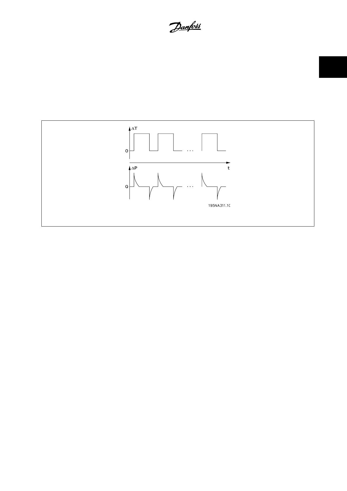
Tightly enclosed equipment is susceptible to water build-up inside the enclosure. This is especially the case where equipment is exposed to ambient
temperature differences under wet conditions. As a decreasing ambient temperature lowers the surface temperature inside the enclosure, water vapor
tends to condensate. At the same time, pressure inside the enclosure will drop and cause humid air from the outside to penetrate non-hermetic polymer
gasket materials and cable connectors. When the enclosure heats up again, only the vaporized water will escape, leaving more and more condensed
water inside the enclosure. This can lead to water build-up inside the enclosure and eventually cause malfunction. The phenomenon is illustrated in the
figure, with a cyclic temperature fluctuation.
Figure 1.10: The pumping effect in tight enclosures
Build-up of water inside enclosures can be prevented by membranes that prevent fluids from penetrating but allow for vapor to pass, as known from
fabrics used for outdoor clothing. A special cable connector with this kind of material is offered by Danfoss to eliminate this problem. The cable connector
should be used in applications exposed to frequent temperature fluctuations and humid environments as in equipment used only during daytime where
the inside temperature tends to fall to the ambient temperature during the night.
1.2.8 Installation Flexibility
Danfoss decentralized solutions offer exceptional installation flexibility. Flexibility is supported by a number of benefits:
Mountable on Danfoss geared motors
Decentralized panel mounting possible
Handheld control panels
PC software for configuring and logging
Single or double-sided installation
•Service switch optional
Brake chopper and resistor optional
External 24 V backup supply optional
M12 connections for external sensors optional
Han 10E motor connector optional
Serial communication bus support (Profibus DP V1, DeviceNet, AS-Interface)
Compatibility with standard line power systems (TN, TT, IT, delta-grounded)
For further details, see the chapter on
The Decentralized Product Range
.
VLT
®
Decentral FCD 300 Design Guide 1 The Decentral Concept
MG.90.S1.22 - VLT
®
is a registered Danfoss trademark
1-9
1
1.3 Application Examples
Danfoss has completed a wide range of applications in many different industries. This has given us a valuable experience that has influenced the latest
development of our decentralized products. In the following, we provide illustrative examples of actual installations using Danfoss decentralized products,
and the benefit and value these provide for the customer in these installations.
1.3.1 Beverage - Bottling Line
Figure 1.11: FCD 300 on bottling conveyor
Figure 1.12: FCD 300 on bottling conveyor
Benefits:
Reduced switchboard space as all drives are mounted in the field
Reduced cabling as several drives can be supplied from same circuit
Ease of commissioning over the serial communication bus as the protocol allows for transfer of complete parameters. Once one drive is set up,
its basic program can be copied to any other decentralized drive
The FCD motor performance is markedly superior to all other types
The FCD can be retrofitted to existing motors of nearly any brand or type
The aseptic IP 66 enclosure is ideal for damp bottling hall conditions
All in one box: e.g., service switch, Profibus and power looping
1 The Decentral Concept VLT
®
Decentral FCD 300 Design Guide
1-10
MG.90.S1.22 - VLT
®
is a registered Danfoss trademark
1
1.3.2 Beverage - Packaging Machine
Benefits:
Distributing motor controls in the application releases space for
other purposes in the switchboard
The number of drives in an application can be increased without
extending the switchboard
IP66 enclosure, easy to clean and resistant to strong cleaning
liquids
Same flexibility as with centrally mounted motor controls. De-
centralized motor controls can be adapted for all standard AC
motors, and feature same user interface and same numbers on
connectors
•Profibus integrated
Figure 1.13: Decentral motor controls integrated in packag-
ing machine
1.3.3 Food - Cocoa Powder Plant
Figure 1.14: Old solution: Motor control - panel mounted
decentrally
Figure 1.15: New Solution: Genuine decentralized motor
control
Benefits:
Easy to expand plant capacity
•No need for switchboard
Visible LED for status
Service switch integrated in the unit
High enclosure rating IP66
Low cost installation
Less space needed for the new solution
VLT
®
Decentral FCD 300 Design Guide 1 The Decentral Concept
MG.90.S1.22 - VLT
®
is a registered Danfoss trademark
1-11
1
1.3.4 Food Conveyor
Figure 1.16: Efficient space utilization in the food industry
with decentralized motor controls from Danfoss
Figure 1.17: Efficient space utilization in the food industry
with decentralized motor controls from Danfoss
Benefits:
The number of drives in an application can be raised without extending the switchboard
IP66 enclosure, easy to clean and resistant to strong cleaning liquids
Dirt-repelling surface and design prevents dirt and product remains on the drive
Motor or wall mount units available
Same flexibility as with centrally mounted motor controls. Decentralized motor controls adapt to all standard AC motors, features same user
interface and same numbering on connectors
Profibus integrated
1.3.5 Automotive Industry - Hoists and Conveyors
Benefits:
Simple installation
AS-i or Profibus control optional
Sensor input available within the physical size of the unit
Separate 24V supply for sensors and bus
Brake supply and control built-in
Easy pluggable remote control panel
Connectors for looping (T-connector) integrated in the installa-
tion box
Low installation and component costs
No additional and expensive EMC connectors needed
Compact and space saving
Easy to install and commission
Input for motor thermistor monitoring
1 The Decentral Concept VLT
®
Decentral FCD 300 Design Guide
1-12
MG.90.S1.22 - VLT
®
is a registered Danfoss trademark
1
1.3.6 Retrofit in Existing Applications
Benefits:
No need for a big control cabinet thanks to the decentralized
motor controls.
No expensive wiring: All motors use existing power cables, pipes
and local switches
All motor controls can be controlled from the existing centralized
cabinet via Profibus
Figure 1.18: Retrofitting on existing application with speed
control
1.4 Product Design Guide
1.4.1 The Decentralized Product Range
The Danfoss decentralized products comprise for adjustable frequency drives VLT Decentral FCD 300 and VLT Drive Motor FCM 300 in their different
installation/mounting concept. This Design Guide gives detailed information about the FCD 300 products only. For further information about FCM 300,
please see the FCM Design Guide: MG03Hxyy
VLT
®
Decentral FCD 300:
0.5–4 hp [0.37–3.3 kW], 3 x 300–480 V
Main applications
- Conveyor in wash down areas
- Packages conveyors
- In/out feed conveyors
VLT
®
Drive Motor FCM 300:
0.75–10 hp [0.55–7.5 kW], 3 x 380–480 V
Main applications
- Fans (Air handling units)
- Pumps
- Air conveyors
VLT
®
Decentral FCD 300 Design Guide 1 The Decentral Concept
MG.90.S1.22 - VLT
®
is a registered Danfoss trademark
1-13
1
1.4.2 Flexible Installation Options
Danfoss decentralized products can be adapted for mounting using the following options - each offering specific benefits:
FCD 300:
1. Stand-alone close to the motor (
wall-mounted
)
Free choice of motor brand
Easy retrofitting to existing motor
Easy interfacing to motor (short cable)
Easy access for diagnosis and optimal serviceability
2. Mounted directly on the motor (
motor-mounted
)
Fair choice of motor brands
No need for shielded motor cable
3. “Pre-mounted” on Danfoss Bauer geared motors
A fixed combination of motor and electronics supplied by one
supplier
Easy mounting, only one unit
No need for shielded motor cable
Clear responsibility regarding the complete solution
As the electronic parts are common - same function of terminals, similar
operation and similar parts and spare parts for all drives - you are free to
mix the three mounting concepts.
1 The Decentral Concept VLT
®
Decentral FCD 300 Design Guide
1-14
MG.90.S1.22 - VLT
®
is a registered Danfoss trademark
1
FCM 300:
4. Motor integrated (FCM 300 Solution)
Motor and drive perfectly matched
Optimized compact unit
No need for programming motor data
1.4.3 Configuring a Product
The decentralized motor control FCD 300 series are configured with a type code string (
see also Ordering
):
FCD 3xx P T4 P66 R1 XX Dx Fxx Txx C0
AC line voltage
FCD 300 is available for connection to AC line voltage 3 phase 380–480
V.
Choice of adjustable frequency drive
The adjustable frequency drive must be chosen on the basis of the
present motor current at maximum loading of the unit. The adjustable
frequency drive's rated output current I
INV.
must be equal to or greater
than the required motor current.
Typical shaft output
P
INV.
Type [kW] [HP]
303 0.37 0.50
305 0.55 0.75
307 0.75 1.0
311 1.1 1.5
315 1.5 2.0
322 2.2 3.0
330 3.0 4.0
335** 3.3 5.0*
* at motor/AC line voltage 3 x 460–480 V
** t
amb
max. 95°F [35°C]
1.4.4 Enclosure
FCD 300 units are protected against water and dust as standard.
See also the section entitled
Technical data
for further details.
1.4.5 Brake
FCD 300 is available with or without an integral brake module. See also the section entitled
Brake Resistors
for ordering a brake resistor.
EB version including mechanical brake control/supply.
1.4.6 24 V External Supply
Backup of control supply with 24 V DC is available in EX and EB versions of FCD 300.
VLT
®
Decentral FCD 300 Design Guide 1 The Decentral Concept
MG.90.S1.22 - VLT
®
is a registered Danfoss trademark
1-15
1
  • Page 1 1
  • Page 2 2
  • Page 3 3
  • Page 4 4
  • Page 5 5
  • Page 6 6
  • Page 7 7
  • Page 8 8
  • Page 9 9
  • Page 10 10
  • Page 11 11
  • Page 12 12
  • Page 13 13
  • Page 14 14
  • Page 15 15
  • Page 16 16
  • Page 17 17
  • Page 18 18
  • Page 19 19
  • Page 20 20
  • Page 21 21
  • Page 22 22
  • Page 23 23
  • Page 24 24
  • Page 25 25
  • Page 26 26
  • Page 27 27
  • Page 28 28
  • Page 29 29
  • Page 30 30
  • Page 31 31
  • Page 32 32
  • Page 33 33
  • Page 34 34
  • Page 35 35
  • Page 36 36
  • Page 37 37
  • Page 38 38
  • Page 39 39
  • Page 40 40
  • Page 41 41
  • Page 42 42
  • Page 43 43
  • Page 44 44
  • Page 45 45
  • Page 46 46
  • Page 47 47
  • Page 48 48
  • Page 49 49
  • Page 50 50
  • Page 51 51
  • Page 52 52
  • Page 53 53
  • Page 54 54
  • Page 55 55
  • Page 56 56
  • Page 57 57
  • Page 58 58
  • Page 59 59
  • Page 60 60
  • Page 61 61
  • Page 62 62
  • Page 63 63
  • Page 64 64
  • Page 65 65
  • Page 66 66
  • Page 67 67
  • Page 68 68
  • Page 69 69
  • Page 70 70
  • Page 71 71
  • Page 72 72
  • Page 73 73
  • Page 74 74
  • Page 75 75
  • Page 76 76
  • Page 77 77
  • Page 78 78
  • Page 79 79
  • Page 80 80
  • Page 81 81
  • Page 82 82
  • Page 83 83
  • Page 84 84
  • Page 85 85
  • Page 86 86
  • Page 87 87
  • Page 88 88
  • Page 89 89
  • Page 90 90
  • Page 91 91
  • Page 92 92
  • Page 93 93
  • Page 94 94
  • Page 95 95
  • Page 96 96
  • Page 97 97
  • Page 98 98
  • Page 99 99
  • Page 100 100
  • Page 101 101
  • Page 102 102
  • Page 103 103
  • Page 104 104
  • Page 105 105
  • Page 106 106
  • Page 107 107
  • Page 108 108
  • Page 109 109
  • Page 110 110
  • Page 111 111
  • Page 112 112
  • Page 113 113
  • Page 114 114
  • Page 115 115
  • Page 116 116
  • Page 117 117
  • Page 118 118
  • Page 119 119
  • Page 120 120
  • Page 121 121
  • Page 122 122
  • Page 123 123
  • Page 124 124
  • Page 125 125
  • Page 126 126
  • Page 127 127
  • Page 128 128
  • Page 129 129
  • Page 130 130
  • Page 131 131
  • Page 132 132
  • Page 133 133
  • Page 134 134
  • Page 135 135
  • Page 136 136
  • Page 137 137
  • Page 138 138
  • Page 139 139
  • Page 140 140
  • Page 141 141
  • Page 142 142
  • Page 143 143
  • Page 144 144
  • Page 145 145
  • Page 146 146
  • Page 147 147
  • Page 148 148
  • Page 149 149
  • Page 150 150
  • Page 151 151
  • Page 152 152
  • Page 153 153
  • Page 154 154
  • Page 155 155
  • Page 156 156
  • Page 157 157
  • Page 158 158
  • Page 159 159
  • Page 160 160
  • Page 161 161
  • Page 162 162
  • Page 163 163
  • Page 164 164
  • Page 165 165
  • Page 166 166
  • Page 167 167
  • Page 168 168
  • Page 169 169
  • Page 170 170
  • Page 171 171
  • Page 172 172
  • Page 173 173

Danfoss VLT Decentral Drive FCD 300 (Legacy Product) User guide

Type
User guide

Ask a question and I''ll find the answer in the document

Finding information in a document is now easier with AI