
YAMAHA ELECTRONICS CORPORATION, USA
6660 ORANGETHORPE AVE., BUENA PARK, CALIF. 90620, U.S.A.
YAMAHA CANADA MUSIC LTD.
135 MILNER AVE., SCARBOROUGH, ONTARIO M1S 3R1, CANADA
YAMAHA ELECTRONIK EUROPA G.m.b.H.
SIEMENSSTR. 22-34, 25462 RELLINGEN BEI HAMBURG, GERMANY
YAMAHA ELECTRONIQUE FRANCE S.A.
RUE AMBROISE CROIZAT BP70 CROISSY-BEAUBOURG 77312 MARNE-LA-VALLEE CEDEX02, FRANCE
YAMAHA ELECTRONICS (UK) LTD.
YAMAHA HOUSE, 200 RICKMANSWORTH ROAD WATFORD, HERTS WD18 7GQ, ENGLAND
YAMAHA SCANDINAVIA A.B.
J A WETTERGRENS GATA 1, BOX 30053, 400 43 VÄSTRA FRÖLUNDA, SWEDEN
YAMAHA MUSIC AUSTRALIA PTY, LTD.
17-33 MARKET ST., SOUTH MELBOURNE, 3205 VIC., AUSTRALIA
©
2005 All rights reserved.
Printed in Malaysia WF72260
YSP-800
YSP-800
Digital Sound Projector
Système Acoustique Numérique
G
OWNER'S MANUAL
MODE D'EMPLOI
BEDIENUNGSANLEITUNG
BRUKSANVISNING
MANUALE DI ISTRUZIONI
MANUAL DE INSTRUCCIONES
GEBRUIKSAANWIJZING
This product mainly uses lead-free solder.
Cet appareil utilise principalement de la soudure sans plomb.
Dieses Produkt verwendet hauptsächlich bleifreies Lot.
I den här produkten används huvudsakligen blyfri lödmetall.
Questo prodotto usa principalmente lega per saldatura senza piombo.
Este producto utiliza principalmente soldadura sin plomo.
Dit product maakt hoofdzakelijk gebruik van loodvrij soldeer.
YSP-800_G-cv.fm Page 1 Monday, July 4, 2005 2:14 AM

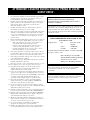
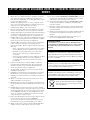
CAUTION: READ THIS BEFORE OPERATING THIS UNIT.
1 To assure the finest performance, please read this manual
carefully. Keep it in a safe place for future reference.
2 Install this sound system in a well ventilated, cool, dry, clean
place with at least 5 cm of space above (or below) this unit –
away from direct sunlight, heat sources, vibration, dust, moisture,
and/or cold.
3 Locate this unit away from other electrical appliances, motors, or
transformers to avoid humming sounds.
4 Do not expose this unit to sudden temperature changes from cold
to hot, and do not locate this unit in an environment with high
humidity (i.e. a room with a humidifier) to prevent condensation
inside this unit, which may cause an electrical shock, fire,
damage to this unit, and/or personal injury.
5 Avoid installing this unit where foreign object may fall onto this
unit and/or this unit may be exposed to liquid dripping or
splashing. On the top of this unit, do not place:
– Other components, as they may cause damage and/or
discoloration on the surface of this unit.
– Burning objects (i.e. candles), as they may cause fire, damage
to this unit, and/or personal injury.
– Containers with liquid in them, as they may fall and liquid
may cause electrical shock to the user and/or damage to this
unit.
6 Do not cover this unit with a newspaper, tablecloth, curtain, etc.
in order not to obstruct heat radiation. If the temperature inside
this unit rises, it may cause fire, damage to this unit, and/or
personal injury.
7 Do not plug in this unit to a wall outlet until all connections are
complete.
8 Do not operate this unit upside-down. It may overheat, possibly
causing damage.
9 Do not use force on switches, knobs and/or cords.
10 When disconnecting the power cable from the wall outlet, grasp
the plug; do not pull the cable.
11 Do not clean this unit with chemical solvents; this might damage
the finish. Use a clean, dry cloth.
12 Only voltage specified on this unit must be used. Using this unit
with a higher voltage than specified is dangerous and may cause
fire, damage to this unit, and/or personal injury. YAMAHA will
not be held responsible for any damage resulting from use of this
unit with a voltage other than specified.
13 Do not attempt to modify or fix this unit. Contact qualified
YAMAHA service personnel when any service is needed.
The cabinet should never be opened for any reasons.
14 When not planning to use this unit for long periods of time (i.e.
vacation), disconnect the AC power plug from the wall outlet.
15 Be sure to read the “TROUBLESHOOTING” section on
common operating errors before concluding that this unit is
faulty.
16 Before moving this unit, press STANDBY/ON to set this unit in
standby mode, and disconnect the AC power plug from the wall
outlet.
17 Condensation will form when the surrounding temperature
changes suddenly. Disconnect the power cable from the outlet,
then leave the unit alone.
18 When using the unit for a long time, the unit may become warm.
Turn the power off, then leave the unit alone for cooling.
19 Install this unit near the AC outlet and where the AC power plug
can be reached easily.
CAUTION: READ THIS BEFORE OPERATING THIS UNIT.
WARNING
TO REDUCE THE RISK OF FIRE OR ELECTRIC SHOCK,
DO NOT EXPOSE THIS UNIT TO RAIN OR MOISTURE.
This unit is not disconnected from the AC power source as
long as it is connected to the AC wall outlet, even if this unit
itself is turned off. This state is called the standby mode. In
this state, this unit is designed to consume a very small
quantity of power.
FOR U.K. CUSTOMERS
If the socket outlets in the home are not suitable for the plug
supplied with this appliance, it should be cut off and an
appropriate 3 pin plug fitted. For details, refer to the
instructions described below. Note that the plug severed from
the mains lead must be destroyed, as a plug with bared
flexible cord is hazardous if engaged in a live socket outlet.
IMPORTANT
THE WIRES IN MAINS LEAD ARE COLOURED IN
ACCORDANCE WITH THE FOLLOWING CODE:
Blue: NEUTRAL
Brown: LIVE
As the colours of the wires in the mains lead of this apparatus
may not correspond with the coloured markings identifying
the terminals in your plug, proceed as follows:
The wire which is coloured BLUE must be connected to the
terminal which is marked with the letter N or coloured
BLACK. The wire which is coloured BROWN must be
connected to the terminal which is marked with the letter L or
coloured RED. Make sure that neither core is connected to the
earth terminal of the three pin plug.
CAUTION
Danger of explosion if battery is incorrectly replaced. Replace
only with the same or equivalent type.
CAUTION
Use of controls or adjustments or performance of procedures
other than those specified herein may result in hazardous
radiation exposure.

1
PREPARATIONINTRODUCTION
BASIC
OPERATION
ADVANCED
OPERATION
ADDITIONAL
INFORMATION
SETUP
English
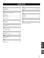
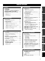
OVERVIEW ........................................................... 2
FEATURES............................................................. 3
USING THIS MANUAL ........................................ 4
SUPPLIED ACCESSORIES ................................. 5
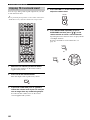
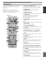
CONTROLS AND FUNCTIONS ......................... 6
Front panel ................................................................. 6
Front panel display .................................................... 7
Rear panel .................................................................. 8
Remote control........................................................... 9
INSTALLATION ................................................. 11
Before installing this unit......................................... 11
Installing this unit .................................................... 11
CONNECTIONS .................................................. 14
Connecting a TV...................................................... 15
Connecting a DVD player/recorder ......................... 16
Connecting a VCR................................................... 17
Connecting a digital satellite tuner
or a cable TV tuner.............................................. 18
Connecting other external components ................... 19
Connecting a subwoofer .......................................... 20
Connecting the power supply cable......................... 21
GETTING STARTED.......................................... 22
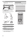
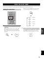
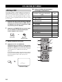
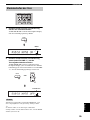
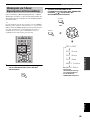
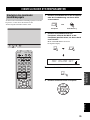
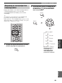
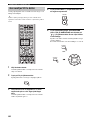
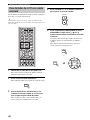
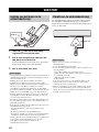
Installing batteries in the remote control ................. 22
Operation range of the remote control..................... 22
Using the remote control ......................................... 23
Turning on the power............................................... 23
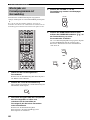
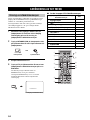
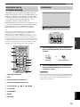
USING SET MENU.............................................. 24
Displaying the OSD................................................. 24
The flow chart of SET MENU................................. 25
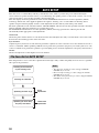
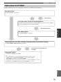
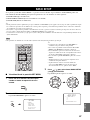
AUTO SETUP....................................................... 26
The flow chart of AUTO SETUP ............................ 26
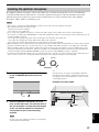
Installing the optimizer microphone........................ 27
Using AUTO SETUP .............................................. 28
USING THE SYSTEM MEMORY .................... 34
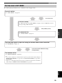
Saving settings......................................................... 34
Loading settings....................................................... 35
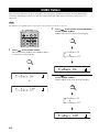
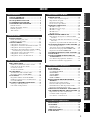
PLAYBACK ..........................................................37
Selecting the input source........................................ 37
Playing back sources ............................................... 38
Adjusting the volume............................................... 38
Muting the sound ..................................................... 39
BEAM MODE .......................................................40
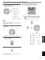
5 beam mode............................................................ 41
Stereo plus 3 beam mode......................................... 41
3 beam mode............................................................ 42
Stereo mode ............................................................. 42
Target mode............................................................. 43
ENJOYING SURROUND SOUND.....................44
Enjoying 2-channel sources
in surround sound ................................................ 45
Enjoying TV in surround sound .............................. 46
Adjusting surround mode parameters...................... 47
USING SOUND FIELD PROGRAMS................49
What is a sound field? ............................................. 49
Turning on CINEMA DSP programs ...................... 50
Turning off CINEMA DSP programs ..................... 51
Adjusting CINEMA DSP levels .............................. 51
USING THE VOLUME MODE ..........................52
USING TruBass.....................................................54
USING THE SLEEP TIMER ..............................55
Setting the sleep timer ............................................. 55
Canceling the sleep timer ........................................ 56
BASIC SETUP.......................................................57
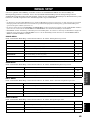
MANUAL SETUP.................................................63
Using MANUAL SETUP........................................ 64
BEAM MENU ......................................................... 65
SOUND MENU....................................................... 69
INPUT MENU......................................................... 71
DISPLAY MENU.................................................... 73
ADJUSTING SYSTEM PARAMETERS ...........75
Setting the maximum volume level ......................... 75
Protecting the current settings ................................. 76
Initializing the current settings ................................ 77
Adjusting the audio balance .................................... 78
SELECTING THE INPUT MODE .....................81
REMOTE CONTROL FEATURES ...................82
Setting remote control codes ................................... 82
Controlling other components ................................. 83
Using the TV macro ................................................ 85
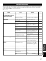
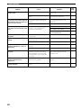
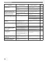
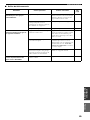
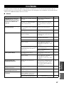
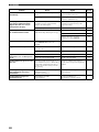
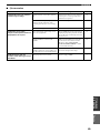
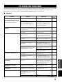
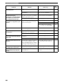
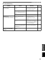
TROUBLESHOOTING .......................................87
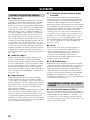
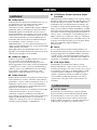
GLOSSARY...........................................................90
Audio formats .......................................................... 90
Audio information ................................................... 90
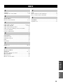
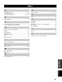
INDEX....................................................................91
SPECIFICATIONS...............................................92
CONTENTS
INTRODUCTION
PREPARATION
SETUP
BASIC OPERATION
ADVANCED OPERATION
ADDITIONAL INFORMATION

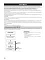
OVERVIEW
2
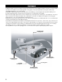
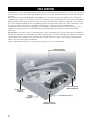
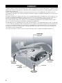
It is generally accepted that in order to fully enjoy the benefits of surround sound at home, you must endure the agony of
wiring and installing a great number of speakers in the hope that your listening room will give you the same kind of
surround sound experience as your local movie theater.
YAMAHA YSP-800 Digital Sound Projector challenges this preconception that complicated speaker setup and
troublesome wiring go hand-in-hand with the enjoyment of multi-channel surround sound.
This slimline unit does away with the need for complicated wiring and installation worries, leaving you with a unit that is
not only easy to set up, but which is also capable of reproducing the kind of powerful surround sound you have been
waiting for from its built-in subwoofers (2) and individual speakers (21).
You can fine-tune the parameters of this unit to adjust the delay time for separate sound beams, resulting in highly
directional sound that comes in on the listening position from all directions.
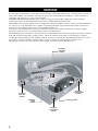
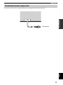
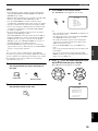
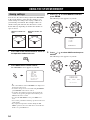
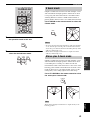
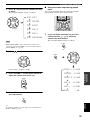
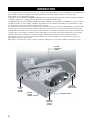
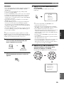
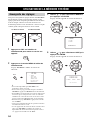
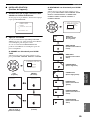
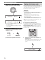
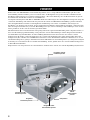
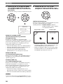
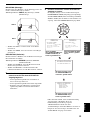
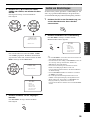
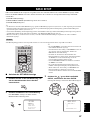
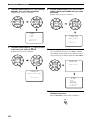
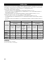
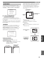
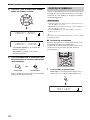
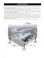
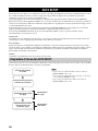
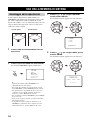
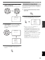
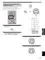
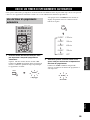
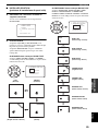
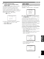
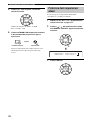
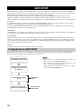
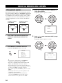
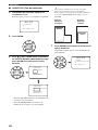
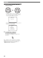
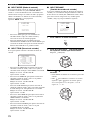
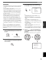
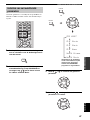
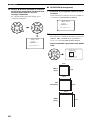
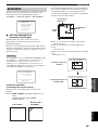
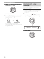
The YSP-800 projects sound beams containing surround sound information for the front right (R), front left (L), surround
right (SR) and surround left (SL) speaker positions, which are reflected off the walls of your listening room before
reaching the actual listening position. With the addition of center (C) sound beams, this Digital Sound Projector creates
true-to-life 5.1 channel surround sound that makes you feel as if there are actual speakers around the room.
Sit back and enjoy the real sound experience of this simple, yet stylish Digital Sound Projector.
OVERVIEW
SL
SR
R
L
C
Listening position
Imaginary
surround left
speaker
Imaginary
surround right
speaker
Imaginary
front left
speaker
Imaginary
front right
speaker
Imaginary
center
speaker

FEATURES
3
INTRODUCTION
English
Digital Sound Projector
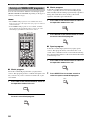
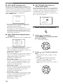
This unit employs the digital sound projector technology
that allows one slim unit to control and steer multiple
channels of sound to generate full, physical 5.1 channel
surround sound, thus eliminating the need for satellite
loudspeakers and cabling normally associated with
conventional surround sound systems. This unit is also
equipped with the following 5 beam modes so that you can
choose the behavior of sound beams that best matches
your listening environment.
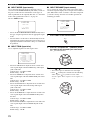
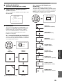
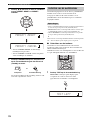
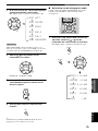
◆ 5 beam mode
◆ ST(STEREO)+3 beam mode
◆ 3 beam mode
◆ Stereo mode
◆ Target mode
Cinema DSP Digital
This unit employs the Cinema DSP Digital technology
developed by YAMAHA Electronics Corp. so that you can
experience movies at home with all the dramatic sound
impact that the director intended to convey.
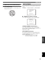
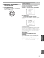
OSD (on-screen display)
This unit employs the OSD which is basically a
superimposed screen image displayed on your video
monitor. The OSD is used to display the system
information or adjust settings for the system parameters.
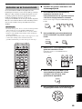
Versatile Remote Control
The supplied remote control come with preset remote
control codes to be used to control the DVD player, VCR,
cable TV tuner and digital satellite tuner connected to this
unit. In addition, the remote control is equipped with the
macro capability so that you can perform a series of
operations with the press of a single button.
AUTO SETUP
This unit employs the automatic sound beam optimization
using the YAMAHA Parametric Room Acoustic
Optimizer (YPAO) technology with the aid of the supplied
optimizer microphone so that you can avoid troublesome
listening-based speaker setup and achieve highly accurate
sound beam adjustments that best match your listening
environment.
Compatibility with the Newest Technologies
This unit employs decoders compatible with Dolby
Digital, DTS (Digital Theater Systems), Dolby Pro Logic,
Dolby Pro Logic II and DTS Neo:6.
◆ Dolby Digital
This is the standard audio signal format used on DVDs and
other purely digital media. This surround technology deliver
high-quality digital audio for up to 5.1 discrete channels to
produce a directional and more realistic effect.
◆ DTS (Digital Theater Systems)
This is an audio signal format used on DVDs and other purely
digital media. This surround technology deliver high-quality
digital audio for up to 5.1 discrete channels to produce a
directional and more realistic effect.
◆ Dolby Pro Logic
This sophisticated, matrix decoding technology up-converts
any 2 channel source audio to a 5.1 channel full bandwidth
playback, resulting in a surround sound experience.
◆ Dolby Pro Logic II
This is fundamentally a redesigned version of Dolby Pro
Logic that employs 2 stereo surround channels, a subwoofer
and a greatly enhanced steering logic. As a result, this
improved technology provides an exceptionally stable sound
field that simulates 5.1 to a much greater degree than the
original Dolby Pro Logic. In addition, Dolby Pro Logic II
features Movie, Music and Game modes specifically designed
for movies, music and games respectively.
◆ DTS Neo:6
This technology decodes the conventional 2 channel sources
for 6 channel playback, enabling playback with the full-range
channels with higher separation. Music mode and Cinema
mode are available to play back music and movie sources
respectively.
The “ ” logo and “Cinema DSP” are registered
trademarks of YAMAHA Corporation.
Manufactured under license from Dolby Laboratories.
“Dolby”, “Pro Logic”, and the double-D symbol are trademarks
of Dolby Laboratories.
“DTS”, and “Neo:6” are trademarks of Digital Theater Systems,
Inc.
Manufactured under license from 1 Ltd. Worldwide patents
applied for.
The ‘ ’ logo and ‘Digital Sound Projector
™
’ are trademarks
of 1 Ltd.
TruBass, SRS and the “ ” symbol are registered trademarks
of SRS Labs, Inc. TruBass technology is incorporated under
license from SRS Labs, Inc.
FEATURES

USING THIS MANUAL
4
• This manual describes how to connect and operate this unit. For details regarding the operation of external components, refer to the
supplied owner’s manual for the component.
• Some operations can be performed by using either the buttons on the main unit or on the remote control. In such cases, the operation is
described using remote control operation.
• y indicates a tip for your operation.
• This manual is printed prior to production. Design and specifications are subject to change in part as a result of improvements, etc. In
case of differences between the manual and product, the product has priority.
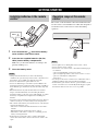
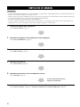
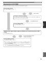
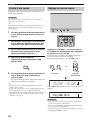
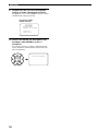
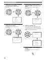
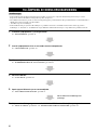
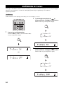
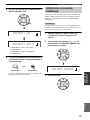
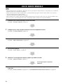
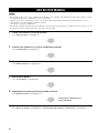
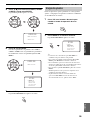
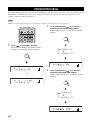
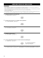
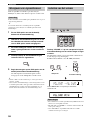
1 Install this unit in your listening room.
See “INSTALLATION” on page 11.
2 Connect this unit to your TV and other external components.
See “CONNECTIONS” on page 14.
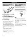
3 Prepare the remote control and turn on the power of this unit.
See “GETTING STARTED” on page 22.
4 Run AUTO SETUP.
See “AUTO SETUP” on page 26.
5 Play back a source and enjoy surround sound.
See “PLAYBACK” on page 37.
6 Run MANUAL SETUP and set remote control codes to fine-tune settings.
See “MANUAL SETUP” on page 63 and “REMOTE CONTROL FEATURES” on page 82.
USING THIS MANUAL
Notes
If you want to make additional settings
and adjustments

SUPPLIED ACCESSORIES
5
INTRODUCTION
English
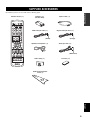
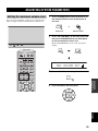
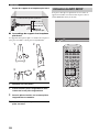
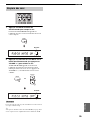
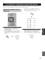
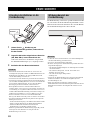
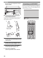
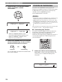
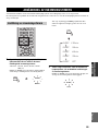
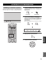
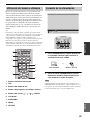
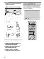
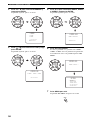
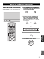
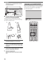
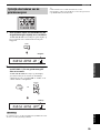
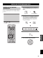
Check that you have received all of the following parts.
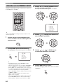
SUPPLIED ACCESSORIES
TV
POWER
2
1
STEREO
SLEEP
CH LEVEL MENU
RETURN
TEST
TV VOL
VOLUME
MUTE TV INPUT TV MUTE
ENTER
SURROUND
OFF
CODE SET
SPORTS
AV
POWER
STANDBY/ON
3
4
56
789
0
+10
5BEAM
ST+3BEAM
3BEAM
TARGET
MUSIC MOVIE VOL MODE
INPUTMODE
MACROINPUT2INPUT1
TV
STBVCRDVD
AUX
YSP
CINEMA DSP
CH
TV
Remote control (×1)
Batteries (×2)
(AA, R6, UM-3)
OSD video pin cable (×1)
Optimizer microphone (×1)
Fastener (×4)
Audio pin cable (×1)
Digital audio pin cable (×1)
Optical cable (×1)
Cable clamp (×1)
Cardboard microphone
stand (×1)
(Orange)
(White/Red)
(Yellow)

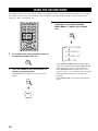
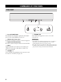
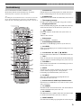
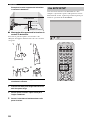
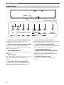
CONTROLS AND FUNCTIONS
6
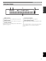
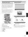
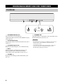
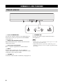
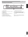
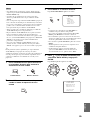
1 OPTIMIZER MIC jack
Use to connect the supplied optimizer microphone to be
used to run AUTO SETUP (see page 27).
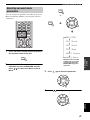
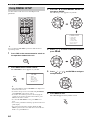
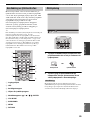
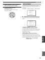
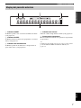
2 Front panel display
Shows information about the operational status of this
unit.
3 Remote control sensor
Receives infrared signals from the remote control.
4 INPUT
Press repeatedly to switch between input sources (TV,
VCR, DVD or AUX). See page 37 for details.
5 VOLUME –/+
Controls the volume level of all audio channels (see
page 38).
6 STANDBY/ON
Turns on the power of this unit or sets it to the standby
mode (see page 23).
• When you turn on the power of this unit, you will hear a click
and there will be a 4 to 5-second delay before it can reproduce
sound.
• In the standby mode, this unit consumes a small amount of
power in order to receive infrared-signals from the remote
control.
CONTROLS AND FUNCTIONS
Front panel
1 2 3
4 5 6
STANDBY/ONVOLUME
+
INPUT
Notes

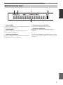
CONTROLS AND FUNCTIONS
7
INTRODUCTION
English
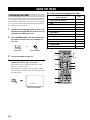
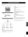
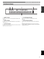
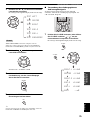
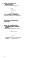
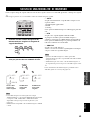
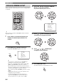
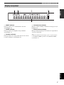
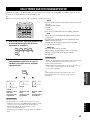
1 NIGHT indicator
Lights up when you select a volume mode (see page 52).
2 SLEEP indicator
Lights up when the sleep timer is turned on (see page 55).
3 Decoder indicators
Light up when the corresponding decoder of this unit is in
operation (see page 44).
4 Volume level indicator
Shows the current volume level (see page 38).
5 Multi-information display
Shows information when you adjust the parameters of this
unit.
y
You can adjust the brightness of the front panel display using the
DISPLAY MENU parameters in MANUAL SETUP (see
page 73).
Front panel display
NIGHT SLEEP PCM PL
m
ft
mS
dB
VOLDIGITAL
5
412 3

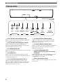
CONTROLS AND FUNCTIONS
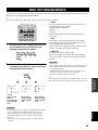
8
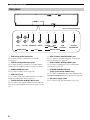
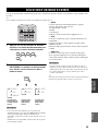
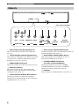
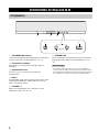
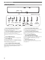
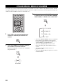
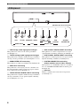
1 VCR analog audio input jacks
Use to make an analog connection to your VCR
(see page 17).
2 TV/STB analog audio input jacks
Use to make an analog connection to your TV, digital
satellite tuner and cable TV tuner (see pages 15 and 18).
3 SUBWOOFER OUT jack
Use to connect a subwoofer (see page 20).
4 VIDEO OUT jack
Use to connect to the video input terminal of your TV to
display the OSD of this unit (see page 15).
5 TV/STB OPTICAL DIGITAL INPUT jack
Use to connect a TV, digital satellite tuner and cable TV
tuner via an optical digital connection (see pages 15 and
18).
6 AUX OPTICAL DIGITAL INPUT jack
Use to connect an external component via an optical
digital connection (see page 19).
7 DVD COAXIAL DIGITAL INPUT jack
Use to connect a DVD player via a coaxial digital
connection (see page 16).
8 SYSTEM CONNECTOR jack
(U.S.A. and Canada models only)
Use to connect a YAMAHA subwoofer equipped with a
SYSTEM CONNECTOR jack to this unit (see page 20).
9 AC power supply cable
Use to connect to the AC wall outlet (see page 21).
Rear panel
9
1234 5 6 7 8
VCR
SUBWOOFER
TV/STB
AUDIO INPUT
OUT
OPTICAL
DIGITAL INPUT
TV/STB VIDEO
AUX
SYSTEM
CONNECTOR
DVD
COAXIAL
(U.S.A. and Canada models)

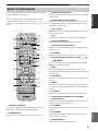
CONTROLS AND FUNCTIONS
9
INTRODUCTION
English
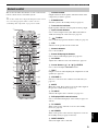
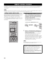
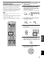
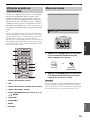
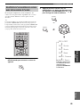
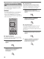
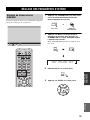
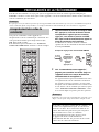
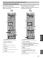
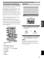
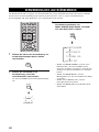
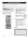
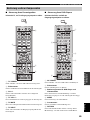
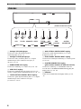
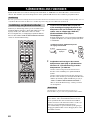
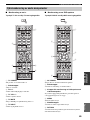
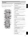
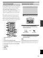
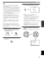
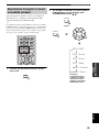
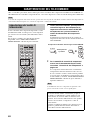
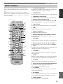
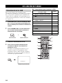
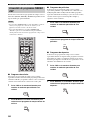
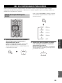
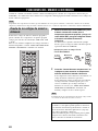
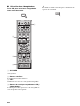
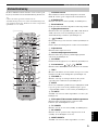
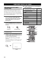
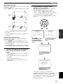
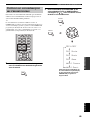
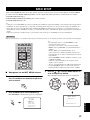
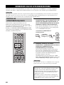
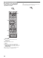
This section describes the function of each control on the
remote control used to control this system.
y
You can also control other components using the remote control
once you set the appropriate remote control codes. See
“Controlling other components” on page 83 for details.
1 Infrared window
Outputs infrared control signals. Aim this window at the
component you want to operate.
2 STANDBY/ON
Sets this system to the standby mode (see page 23).
3 Transmission indicator
Lights up when infrared control signals are being output.
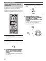
4 Input selector buttons
Use to select an input source (TV, STB, VCR, DVD or
AUX) and change the control area (see page 37).
5 TruBass
Use to effectively reproduce the bass sound (see page 54).
6 YSP
Switches to the operation mode of this unit.
7 Numeric buttons
Use to enter numbers.
8 Sound field program buttons
Use to select sound field programs (see page 49).
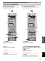
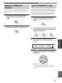
9 CH LEVEL
Adjusts the volume level of each channel (see page 79).
0 Cursor buttons / / / , ENTER
Use to select and adjust SET MENU items.
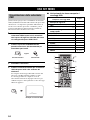
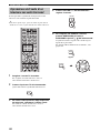
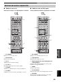
A TEST
Outputs a test tone when adjusting the output level of each
speaker (see page 78).
B VOLUME +/–
Increases or decreases the volume level of this unit (see
page 38).
C MUTE
Mutes the sound. Press again to restore the audio output to
the previous volume level (see page 39).
D TV INPUT
Switches the input source of the TV (see page 83).
E DVD player/VCR control buttons
Use to control the DVD player of the VCR (see pages 83
and 84).
F TV POWER
Turns on the power of the TV or sets it to the standby
mode (see page 83).
G AV POWER
Turns on the power of the selected component or sets it to
the standby mode (see pages 83 and 84).
H INPUT1/INPUT2
Selects the input source of the TV.
Remote control
TV
POWER
2
1
STEREO
SLEEP
CH LEVEL MENU
RETURN
TEST
TV VOL
VOLUME
MUTE TV INPUT TV MUTE
ENTER
SURROUND
OFF
CODE SET
SPORTS
AV
POWER
STANDBY/ON
3
4
56
789
0
+10
5BEAM
ST+3BEAM
3BEAM
MUSIC MOVIE VOL MODE
INPUTMODE
MACROINPUT2INPUT1
TV
STBVCRDVD
AUX
YSP
CINEMA DSP
CH
TARGET
TV
1
2
4
6
7
9
0
A
E
I
J
N
K
O
P
Q
S
5
3
H
M
8
L
D
C
R
B
G
F

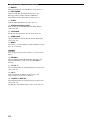
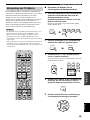
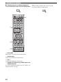
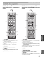
CONTROLS AND FUNCTIONS
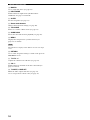
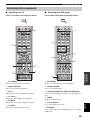
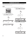
10
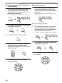
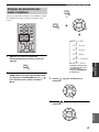
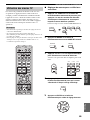
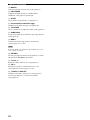
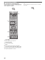
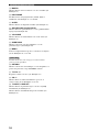
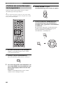
I MACRO
Use to set the TV macro (see page 85).
J INPUTMODE
Switches between input modes (AUTO, DTS or
ANALOG). See page 37 for details.
K SLEEP
Sets the sleep timer (see page 55).
L Beam mode buttons
Change the beam mode settings (see page 40).
M VOL MODE
Turns on or off the volume modes (see page 52).
N SURROUND
Selects the surround mode for playback (see page 44).
O MENU
Displays the setup menu on your TV monitor (see
pages 28, 57 and 64).
The DVD menu is displayed when DVD is selected as the input
source.
P RETURN
Use to select sleep timer settings or return to the previous
SET MENU screen.
Q TV VOL +/–
Adjusts the volume level of the TV (see page 83).
R CH +/–
Switches between channels of the TV or the VCR (see
pages 83 and 84).
S TV MUTE, CODE SET
Mutes the audio output of the TV (see page 83).
Use to set up remote control codes (see page 82).
Note

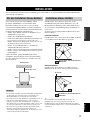
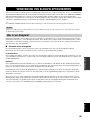
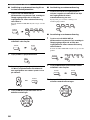
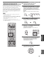
INSTALLATION
11
PREPARATION
English
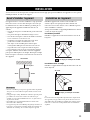
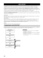
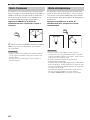
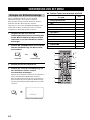
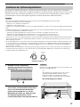
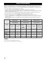
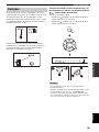
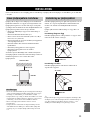
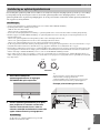
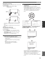
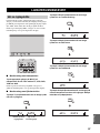
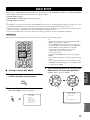
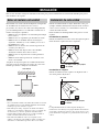
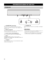
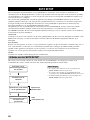
This section describes a suitable installation location to install the unit using a metal wall bracket, a rack or a stand.
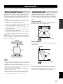
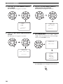
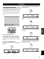
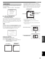
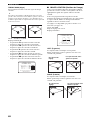
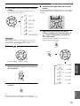
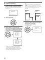
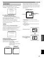
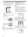
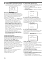
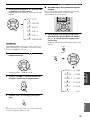
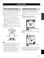
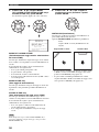
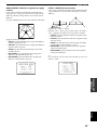
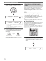
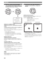
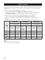
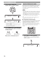
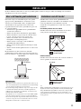
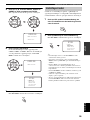
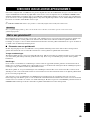
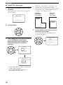
This unit creates surround sound by reflecting projected
sound beams off the walls of your listening room. The
surround sound effects produced by this unit may not be
sufficient when the unit is installed in the following
locations.
• Rooms with surfaces inadequate for reflecting sound
beams
• Rooms with acoustically absorbent surfaces
• Rooms with measurements outside the following range
W (3 to 7 m) x H (2 to 3.5 m) x D (3 to 7 m)
• Rooms with less than 2 m from the listening position to
the speaker positions
• Rooms where objects such as furniture are likely to
obstruct the path of sound beams
• Rooms where the listening position is close to the walls
• Rooms where the listening position is not in front of
this unit
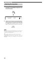
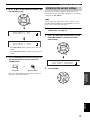
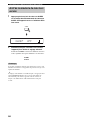
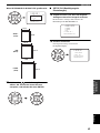
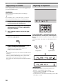
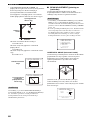
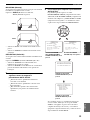
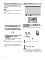
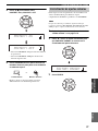
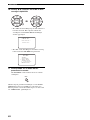
Make sure you leave an adequate amount of ventilation
space so that heat can escape. Make at least 5 cm of space
above or below this unit.
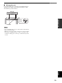
• We do not recommend installing this unit so that it is positioned
directly on the floor of your listening room. Please install this
unit using a metal wall bracket, rack or stand.
• This unit weighs 9.0 kg. Be sure to install this unit where it will
not fall subject to vibrations, such as from an earthquake, and
where it is out of the reach of children.
• When using a cathode-ray tube (CRT) TV, do not install this
unit directly above your TV.
• This unit is shielded against magnetic rays. However, if the
picture on your TV screen becomes blurred or distorted, we
recommend moving the speakers away from your TV.
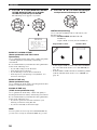
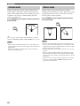
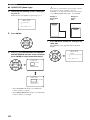
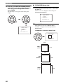
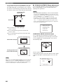
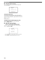
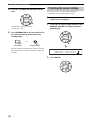
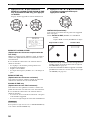
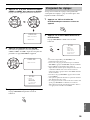
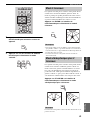
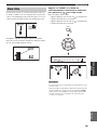
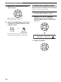
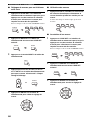
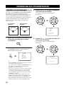
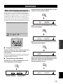
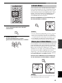
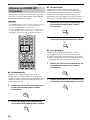
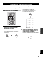
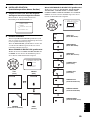
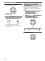
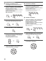
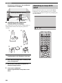
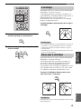
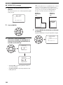
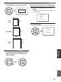
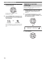
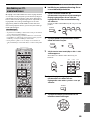
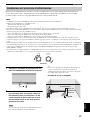
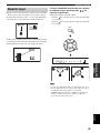
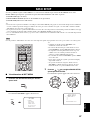
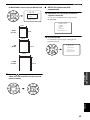
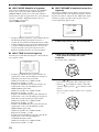
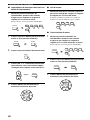
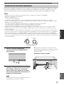
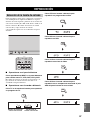
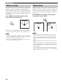
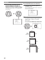
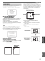
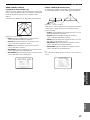
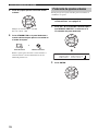
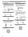
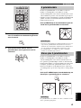
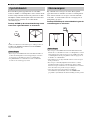
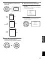
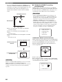
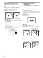
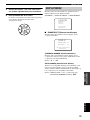
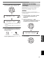
Install this unit where there are no obstacles such as
furniture obstructing the path of sound beams. Otherwise,
the desired surround sound effects may not be achieved.
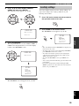
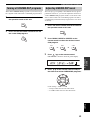
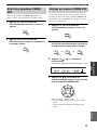
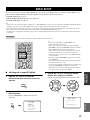
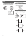
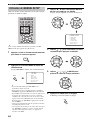
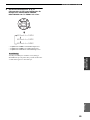
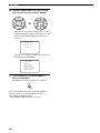
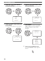
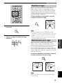
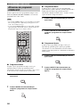
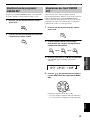
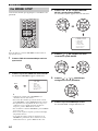
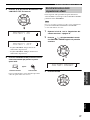
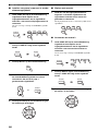
You may install this unit in parallel with the wall or in the
corner.
Parallel installation
Install this unit in the exact center of the wall when it is
measured from the left and right corners.
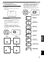
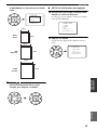
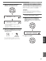
Corner installation
Install this unit in the corner at a 40º to 50º angle from the
adjacent walls.
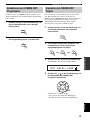
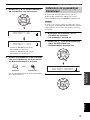
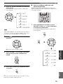
y
The availability of the beam mode depends on the installation
location of this unit (see page 40). All five beam modes are
available for the parallel installation whereas the 3 beam and 5
beam modes are not available for the corner installation.
INSTALLATION
Before installing this unit
Notes
5 cm or more
Rear
Front
Side view
Installing this unit
An object, such as furniture
40° to 50°
An object, such as furniture

12
INSTALLATION
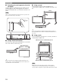
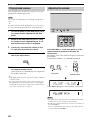
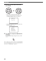
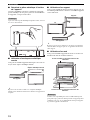
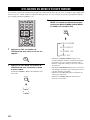
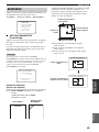
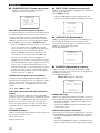
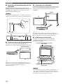
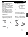
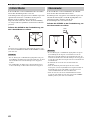
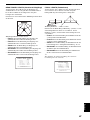
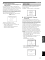
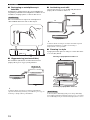
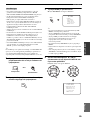
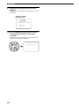
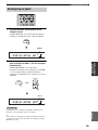
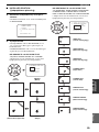
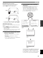
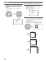
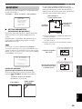
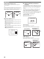
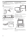
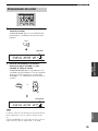
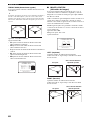
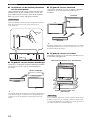
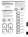
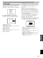
■ Detaching the metal apparatus from the
rear panel
A metal apparatus is attached to the rear panel used for
packing purposes. If the metal apparatus is a nuisance
when you install this unit, you can detach it from the rear
panel.
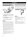
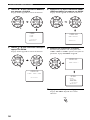
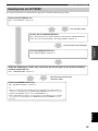
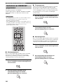
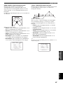
After you detach the metal apparatus from the rear panel, drive
the screws back in using a screwdriver.
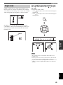
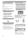
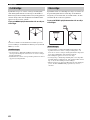
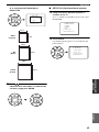
■ Using a metal wall bracket
You can use the optional metal wall bracket to mount this
unit on the wall in your listening room.
y
Refer to the instructions supplied with the metal bracket for
details on how to attach the metal bracket to the wall or how to
attach this unit to the metal bracket.
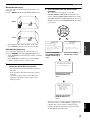
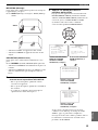
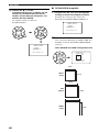
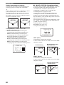
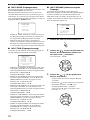
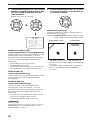
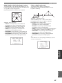
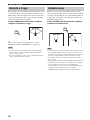
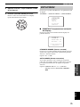
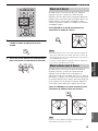
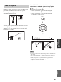
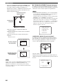
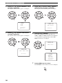
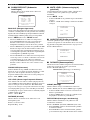
■ Using a stand
You can mount your TV on the stand placed on a
commercially available rack to install this unit under your
TV.
y
Refer to the instructions supplied with the stand for details on
how to install the stand or how to mount this unit and the TV on
the stand.
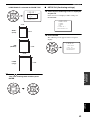
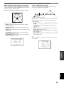
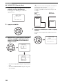
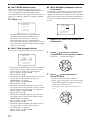
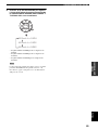
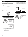
■ Using a rack
You can install this unit either above or under your TV in a
commercially available rack.
Make sure that the rack is large enough to allow adequate
ventilation space around this unit (see page 11) and that it is
strong enough to support the weight of both this unit and your TV.
Note
This unit
TV
Metal wall bracket
Note
TV
This unit
Stand
When this unit is installed above your TV
When this unit is installed under your TV

13
INSTALLATION
PREPARATION
English
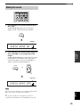
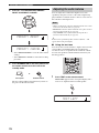
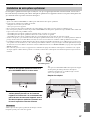
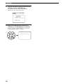
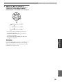
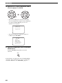
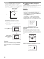
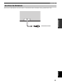
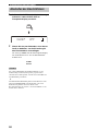
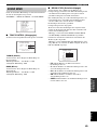
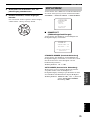
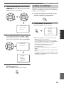
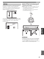
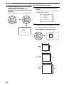
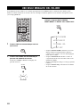
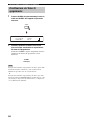
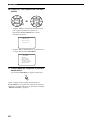
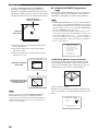
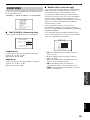
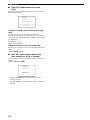
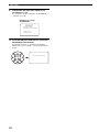
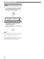
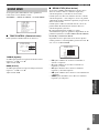
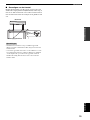
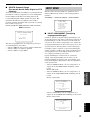
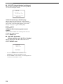
■ Affixing this unit
Peel off the film from each of the four supplied fasteners
and then secure them to the bottom four corners of this
unit and the top of the rack, etc.
• Do not install this unit on top of a slanted surface. This unit may
fall over and cause injury.
• Make sure you wipe the surface of the rack, etc. before securing
the fasteners. Applying the tape to a dirty or wet surface will
weaken the sticking power of the tape, and this unit may fall as
a result.
Notes
1
2
This unit
Peel off
the film
Fasteners

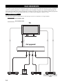
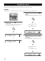
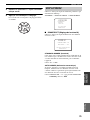
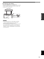
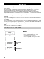
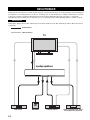
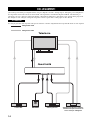
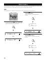
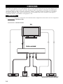
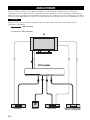
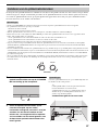
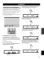
CONNECTIONS
14
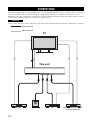
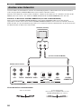
This unit is equipped with two optical digital jacks, one coaxial digital jack and two types of analog jacks for connecting
external components such as your TV, DVD player, VCR, digital satellite tuner, cable TV tuner and game console.
Further, by connecting a subwoofer to this unit, you can enjoy reinforced low bass sounds. For details on how to connect
various types of external components to this unit, see pages 15 to 20.
Do not connect this unit or other components to the main power until all connections between components are complete.
CONNECTIONS
CAUTION
Audio connection
Video connection
DVD player
Subwoofer
This unit
VCR
Digital satellite tuner, cable TV
tuner or game console
TV

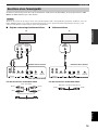
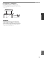
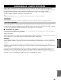
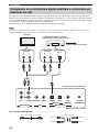
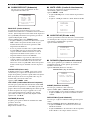
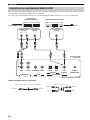
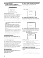
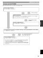
15
CONNECTIONS
PREPARATION
English
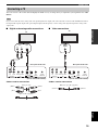
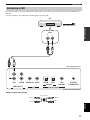
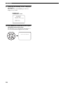
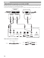
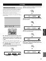
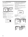
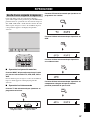
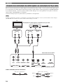
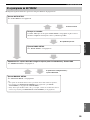
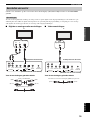
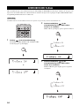
You can connect a TV to this unit and display the OSD for easy viewing when you adjust the system parameters in SET
MENU.
If you connect this unit to the analog audio and optical digital audio output jacks at the same time as shown in the left illustration below,
the digital audio signals output at the optical digital output jack take priority over the analog audio signals output at the analog audio
output jacks.
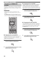
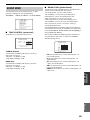
■ Digital and analog audio connections
Cables used for connections
■ Video connections
Cables used for connections
Connecting a TV
Note
VCR
SUBWOOFER
TV/STB
AUDIO INPUT
OUT
OPTICAL
DIGITAL INPUT
TV/STB VIDEO
AUX
SYSTEM
CONNECTOR
DVD
COAXIAL
Rear panel of this unit
TV
Analog audio
output
Optical digital
output
RL
(U.S.A. and Canada models)
Optical cable (supplied)
Audio pin cable
(White)
(Red)
(White)
(Red)
VCR
SUBWOOFER
TV/STB
AUDIO INPUT
OUT
OPTICAL
DIGITAL INPUT
TV/STB VIDEO
AUX
SYSTEM
CONNECTOR
DVD
COAXIAL
TV
Video
input
Rear panel of this unit
(U.S.A. and Canada models)
OSD video pin cable (supplied)
(Yellow)(Yellow)

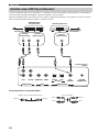
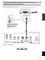
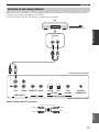
16
CONNECTIONS
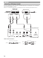
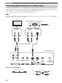
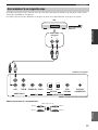
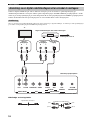
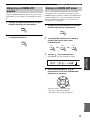
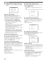
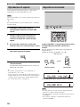
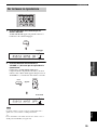
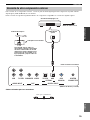
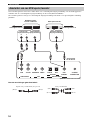
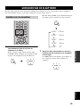
To connect a DVD player/recorder, connect the coaxial digital output jack on your DVD player to the coaxial digital
input jack (DVD COAXIAL) on this unit.
If there is no coaxial digital output jack on your DVD player/recorder, use them with optical digital connection.
Cables used for connections
Connecting a DVD player/recorder
VCR
SUBWOOFER
TV/STB
AUDIO INPUT
OUT
OPTICAL
DIGITAL INPUT
TV/STB VIDEO
AUX
SYSTEM
CONNECTOR
DVD
COAXIAL
Rear panel of this unit
Video signal to a TV
Coaxial digital
output
Analog audio
output
Coaxial digital
output
L
R
DVD/VCR combo
player/recorder
DVD player/recorder
Video signal to a TV
(U.S.A. and Canada models)
Audio pin cable
(White)
(Red)
(White)
(Red)
Digital audio pin cable (supplied)
(Orange)(Orange)

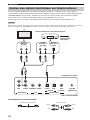
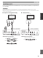
17
CONNECTIONS
PREPARATION
English
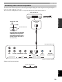
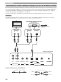
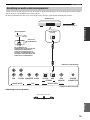
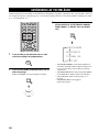
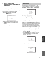
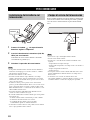
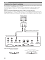
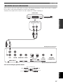
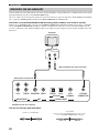
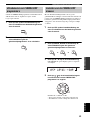
To connect a VCR, connect the analog audio output jacks on your VCR to the analog audio input jacks (VCR R/L) on
this unit.
Connect red plugs to the right jacks and white plugs to the left jacks.
Cables used for connections
Connecting a VCR
VCR
SUBWOOFER
TV/STB
AUDIO INPUT
OUT
OPTICAL
DIGITAL INPUT
TV/STB VIDEO
AUX
SYSTEM
CONNECTOR
DVD
COAXIAL
Video signal to a TV
Rear panel of this unit
Analog audio
output
R
L
VCR
(U.S.A. and Canada models)
Audio pin cable
(White)
(Red)
(White)
(Red)

18
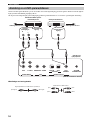
CONNECTIONS
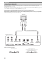
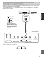
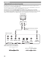
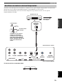
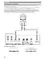
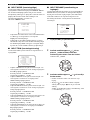
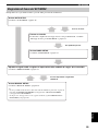
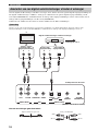
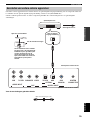
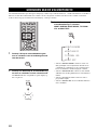
To connect a digital satellite tuner or a cable TV tuner, connect the optical digital output jack on your digital satellite
tuner or cable TV tuner to the optical digital input jack (TV/STB OPTICAL) on this unit. In addition, connect the analog
audio output jacks on your VCR to the analog audio input jacks (TV/STB R/L) on this unit.
Connect red plugs to the right jacks and white plugs to the left jacks.
If your TV and tuner connected to this unit do not support digital broadcasting, connect the analog audio output jacks (TV/STB R/L) on
this unit to the analog audio output jacks on your TV.
Cables used for connections
Connecting a digital satellite tuner or a cable TV tuner
Note
VCR
SUBWOOFER
TV/STB
AUDIO INPUT
OUT
OPTICAL
DIGITAL INPUT
TV/STB VIDEO
AUX
SYSTEM
CONNECTOR
DVD
COAXIAL
Video signal to a TV
Rear panel of this unit
Digital satellite tuner or a cable TV tuner
Optical digital
output
Analog audio
output
L
R
Analog audio
output
L
R
TV
(U.S.A. and Canada models)
Optical cable (supplied)
Audio pin cable
(White)
(Red)
(White)
(Red)
Page is loading ...
Page is loading ...
Page is loading ...
Page is loading ...
Page is loading ...
Page is loading ...
Page is loading ...
Page is loading ...
Page is loading ...
Page is loading ...
Page is loading ...
Page is loading ...
Page is loading ...
Page is loading ...
Page is loading ...
Page is loading ...
Page is loading ...
Page is loading ...
Page is loading ...
Page is loading ...
Page is loading ...
Page is loading ...
Page is loading ...
Page is loading ...
Page is loading ...
Page is loading ...
Page is loading ...
Page is loading ...
Page is loading ...
Page is loading ...
Page is loading ...
Page is loading ...
Page is loading ...
Page is loading ...
Page is loading ...
Page is loading ...
Page is loading ...
Page is loading ...
Page is loading ...
Page is loading ...
Page is loading ...
Page is loading ...
Page is loading ...
Page is loading ...
Page is loading ...
Page is loading ...
Page is loading ...
Page is loading ...
Page is loading ...
Page is loading ...
Page is loading ...
Page is loading ...
Page is loading ...
Page is loading ...
Page is loading ...
Page is loading ...
Page is loading ...
Page is loading ...
Page is loading ...
Page is loading ...
Page is loading ...
Page is loading ...
Page is loading ...
Page is loading ...
Page is loading ...
Page is loading ...
Page is loading ...
Page is loading ...
Page is loading ...
Page is loading ...
Page is loading ...
Page is loading ...
Page is loading ...
Page is loading ...
Page is loading ...
Page is loading ...
Page is loading ...
Page is loading ...
Page is loading ...
Page is loading ...
Page is loading ...
Page is loading ...
Page is loading ...
Page is loading ...
Page is loading ...
Page is loading ...
Page is loading ...
Page is loading ...
Page is loading ...
Page is loading ...
Page is loading ...
Page is loading ...
Page is loading ...
Page is loading ...
Page is loading ...
Page is loading ...
Page is loading ...
Page is loading ...
Page is loading ...
Page is loading ...
Page is loading ...
Page is loading ...
Page is loading ...
Page is loading ...
Page is loading ...
Page is loading ...
Page is loading ...
Page is loading ...
Page is loading ...
Page is loading ...
Page is loading ...
Page is loading ...
Page is loading ...
Page is loading ...
Page is loading ...
Page is loading ...
Page is loading ...
Page is loading ...
Page is loading ...
Page is loading ...
Page is loading ...
Page is loading ...
Page is loading ...
Page is loading ...
Page is loading ...
Page is loading ...
Page is loading ...
Page is loading ...
Page is loading ...
Page is loading ...
Page is loading ...
Page is loading ...
Page is loading ...
Page is loading ...
Page is loading ...
Page is loading ...
Page is loading ...
Page is loading ...
Page is loading ...
Page is loading ...
Page is loading ...
Page is loading ...
Page is loading ...
Page is loading ...
Page is loading ...
Page is loading ...
Page is loading ...
Page is loading ...
Page is loading ...
Page is loading ...
Page is loading ...
Page is loading ...
Page is loading ...
Page is loading ...
Page is loading ...
Page is loading ...
Page is loading ...
Page is loading ...
Page is loading ...
Page is loading ...
Page is loading ...
Page is loading ...
Page is loading ...
Page is loading ...
Page is loading ...
Page is loading ...
Page is loading ...
Page is loading ...
Page is loading ...
Page is loading ...
Page is loading ...
Page is loading ...
Page is loading ...
Page is loading ...
Page is loading ...
Page is loading ...
Page is loading ...
Page is loading ...
Page is loading ...
Page is loading ...
Page is loading ...
Page is loading ...
Page is loading ...
Page is loading ...
Page is loading ...
Page is loading ...
Page is loading ...
Page is loading ...
Page is loading ...
Page is loading ...
Page is loading ...
Page is loading ...
Page is loading ...
Page is loading ...
Page is loading ...
Page is loading ...
Page is loading ...
Page is loading ...
Page is loading ...
Page is loading ...
Page is loading ...
Page is loading ...
Page is loading ...
Page is loading ...
Page is loading ...
Page is loading ...
Page is loading ...
Page is loading ...
Page is loading ...
Page is loading ...
Page is loading ...
Page is loading ...
Page is loading ...
Page is loading ...
Page is loading ...
Page is loading ...
Page is loading ...
Page is loading ...
Page is loading ...
Page is loading ...
Page is loading ...
Page is loading ...
Page is loading ...
Page is loading ...
Page is loading ...
Page is loading ...
Page is loading ...
Page is loading ...
Page is loading ...
Page is loading ...
Page is loading ...
Page is loading ...
Page is loading ...
Page is loading ...
Page is loading ...
Page is loading ...
Page is loading ...
Page is loading ...
Page is loading ...
Page is loading ...
Page is loading ...
Page is loading ...
Page is loading ...
Page is loading ...
Page is loading ...
Page is loading ...
Page is loading ...
Page is loading ...
Page is loading ...
Page is loading ...
Page is loading ...
Page is loading ...
Page is loading ...
Page is loading ...
Page is loading ...
Page is loading ...
Page is loading ...
Page is loading ...
Page is loading ...
Page is loading ...
Page is loading ...
Page is loading ...
Page is loading ...
Page is loading ...
Page is loading ...
Page is loading ...
Page is loading ...
Page is loading ...
Page is loading ...
Page is loading ...
Page is loading ...
Page is loading ...
Page is loading ...
Page is loading ...
Page is loading ...
Page is loading ...
Page is loading ...
Page is loading ...
Page is loading ...
Page is loading ...
Page is loading ...
Page is loading ...
Page is loading ...
Page is loading ...
Page is loading ...
Page is loading ...
Page is loading ...
Page is loading ...
Page is loading ...
Page is loading ...
Page is loading ...
Page is loading ...
Page is loading ...
Page is loading ...
Page is loading ...
Page is loading ...
Page is loading ...
Page is loading ...
Page is loading ...
Page is loading ...
Page is loading ...
Page is loading ...
Page is loading ...
Page is loading ...
Page is loading ...
Page is loading ...
Page is loading ...
Page is loading ...
Page is loading ...
Page is loading ...
Page is loading ...
Page is loading ...
Page is loading ...
Page is loading ...
Page is loading ...
Page is loading ...
Page is loading ...
Page is loading ...
Page is loading ...
Page is loading ...
Page is loading ...
Page is loading ...
Page is loading ...
Page is loading ...
Page is loading ...
Page is loading ...
Page is loading ...
Page is loading ...
Page is loading ...
Page is loading ...
Page is loading ...
Page is loading ...
Page is loading ...
Page is loading ...
Page is loading ...
Page is loading ...
Page is loading ...
Page is loading ...
Page is loading ...
Page is loading ...
Page is loading ...
Page is loading ...
Page is loading ...
Page is loading ...
Page is loading ...
Page is loading ...
Page is loading ...
Page is loading ...
Page is loading ...
Page is loading ...
Page is loading ...
Page is loading ...
Page is loading ...
Page is loading ...
Page is loading ...
Page is loading ...
Page is loading ...
Page is loading ...
Page is loading ...
Page is loading ...
Page is loading ...
Page is loading ...
Page is loading ...
Page is loading ...
Page is loading ...
Page is loading ...
Page is loading ...
Page is loading ...
Page is loading ...
Page is loading ...
Page is loading ...
Page is loading ...
Page is loading ...
Page is loading ...
Page is loading ...
Page is loading ...
Page is loading ...
Page is loading ...
Page is loading ...
Page is loading ...
Page is loading ...
Page is loading ...
Page is loading ...
Page is loading ...
Page is loading ...
Page is loading ...
Page is loading ...
Page is loading ...
Page is loading ...
Page is loading ...
Page is loading ...
Page is loading ...
Page is loading ...
Page is loading ...
Page is loading ...
Page is loading ...
Page is loading ...
Page is loading ...
Page is loading ...
Page is loading ...
Page is loading ...
Page is loading ...
Page is loading ...
Page is loading ...
Page is loading ...
Page is loading ...
Page is loading ...
Page is loading ...
Page is loading ...
Page is loading ...
Page is loading ...
Page is loading ...
Page is loading ...
Page is loading ...
Page is loading ...
Page is loading ...
Page is loading ...
Page is loading ...
Page is loading ...
Page is loading ...
Page is loading ...
Page is loading ...
Page is loading ...
Page is loading ...
Page is loading ...
Page is loading ...
Page is loading ...
Page is loading ...
Page is loading ...
Page is loading ...
Page is loading ...
Page is loading ...
Page is loading ...
Page is loading ...
Page is loading ...
Page is loading ...
Page is loading ...
Page is loading ...
Page is loading ...
Page is loading ...
Page is loading ...
Page is loading ...
Page is loading ...
Page is loading ...
Page is loading ...
Page is loading ...
Page is loading ...
Page is loading ...
Page is loading ...
Page is loading ...
Page is loading ...
Page is loading ...
Page is loading ...
Page is loading ...
Page is loading ...
Page is loading ...
Page is loading ...
Page is loading ...
Page is loading ...
Page is loading ...
Page is loading ...
Page is loading ...
Page is loading ...
Page is loading ...
Page is loading ...
Page is loading ...
Page is loading ...
Page is loading ...
Page is loading ...
Page is loading ...
Page is loading ...
Page is loading ...
Page is loading ...
Page is loading ...
Page is loading ...
Page is loading ...
Page is loading ...
Page is loading ...
Page is loading ...
Page is loading ...
Page is loading ...
Page is loading ...
Page is loading ...
Page is loading ...
Page is loading ...
Page is loading ...
Page is loading ...
Page is loading ...
Page is loading ...
Page is loading ...
Page is loading ...
Page is loading ...
Page is loading ...
Page is loading ...
Page is loading ...
Page is loading ...
Page is loading ...
Page is loading ...
Page is loading ...
Page is loading ...
Page is loading ...
Page is loading ...
Page is loading ...
Page is loading ...
Page is loading ...
Page is loading ...
Page is loading ...
Page is loading ...
Page is loading ...
Page is loading ...
Page is loading ...
Page is loading ...
Page is loading ...
Page is loading ...
Page is loading ...
Page is loading ...
Page is loading ...
Page is loading ...
Page is loading ...
Page is loading ...
Page is loading ...
Page is loading ...
Page is loading ...
Page is loading ...
Page is loading ...
Page is loading ...
Page is loading ...
Page is loading ...
Page is loading ...
Page is loading ...
Page is loading ...
Page is loading ...
Page is loading ...
Page is loading ...
Page is loading ...
Page is loading ...
Page is loading ...
Page is loading ...
Page is loading ...
Page is loading ...
Page is loading ...
Page is loading ...
Page is loading ...
Page is loading ...
Page is loading ...
Page is loading ...
Page is loading ...
Page is loading ...
Page is loading ...
Page is loading ...
Page is loading ...
Page is loading ...
Page is loading ...
Page is loading ...
Page is loading ...
Page is loading ...
Page is loading ...
Page is loading ...
Page is loading ...
Page is loading ...
Page is loading ...
Page is loading ...
Page is loading ...
Page is loading ...
Page is loading ...
Page is loading ...
Page is loading ...
Page is loading ...
Page is loading ...
Page is loading ...
Page is loading ...
Page is loading ...
Page is loading ...
Page is loading ...
Page is loading ...
Page is loading ...
Page is loading ...
Page is loading ...
Page is loading ...
Page is loading ...
Page is loading ...
Page is loading ...
Page is loading ...
Page is loading ...
Page is loading ...
Page is loading ...
Page is loading ...
Page is loading ...
Page is loading ...
Page is loading ...
Page is loading ...
Page is loading ...
Page is loading ...
Page is loading ...
Page is loading ...
Page is loading ...
Page is loading ...
Page is loading ...
Page is loading ...
Page is loading ...
Page is loading ...
Page is loading ...
Page is loading ...
Page is loading ...
Page is loading ...
Page is loading ...
Page is loading ...
Page is loading ...
Page is loading ...
Page is loading ...
Page is loading ...
Page is loading ...
Page is loading ...
Page is loading ...
Page is loading ...
Page is loading ...
Page is loading ...
Page is loading ...
Page is loading ...
Page is loading ...
Page is loading ...
Page is loading ...
Page is loading ...
Page is loading ...
Page is loading ...
Page is loading ...
Page is loading ...
Page is loading ...
Page is loading ...
Page is loading ...
Page is loading ...
Page is loading ...
Page is loading ...
Page is loading ...
Page is loading ...
-
 1
1
-
 2
2
-
 3
3
-
 4
4
-
 5
5
-
 6
6
-
 7
7
-
 8
8
-
 9
9
-
 10
10
-
 11
11
-
 12
12
-
 13
13
-
 14
14
-
 15
15
-
 16
16
-
 17
17
-
 18
18
-
 19
19
-
 20
20
-
 21
21
-
 22
22
-
 23
23
-
 24
24
-
 25
25
-
 26
26
-
 27
27
-
 28
28
-
 29
29
-
 30
30
-
 31
31
-
 32
32
-
 33
33
-
 34
34
-
 35
35
-
 36
36
-
 37
37
-
 38
38
-
 39
39
-
 40
40
-
 41
41
-
 42
42
-
 43
43
-
 44
44
-
 45
45
-
 46
46
-
 47
47
-
 48
48
-
 49
49
-
 50
50
-
 51
51
-
 52
52
-
 53
53
-
 54
54
-
 55
55
-
 56
56
-
 57
57
-
 58
58
-
 59
59
-
 60
60
-
 61
61
-
 62
62
-
 63
63
-
 64
64
-
 65
65
-
 66
66
-
 67
67
-
 68
68
-
 69
69
-
 70
70
-
 71
71
-
 72
72
-
 73
73
-
 74
74
-
 75
75
-
 76
76
-
 77
77
-
 78
78
-
 79
79
-
 80
80
-
 81
81
-
 82
82
-
 83
83
-
 84
84
-
 85
85
-
 86
86
-
 87
87
-
 88
88
-
 89
89
-
 90
90
-
 91
91
-
 92
92
-
 93
93
-
 94
94
-
 95
95
-
 96
96
-
 97
97
-
 98
98
-
 99
99
-
 100
100
-
 101
101
-
 102
102
-
 103
103
-
 104
104
-
 105
105
-
 106
106
-
 107
107
-
 108
108
-
 109
109
-
 110
110
-
 111
111
-
 112
112
-
 113
113
-
 114
114
-
 115
115
-
 116
116
-
 117
117
-
 118
118
-
 119
119
-
 120
120
-
 121
121
-
 122
122
-
 123
123
-
 124
124
-
 125
125
-
 126
126
-
 127
127
-
 128
128
-
 129
129
-
 130
130
-
 131
131
-
 132
132
-
 133
133
-
 134
134
-
 135
135
-
 136
136
-
 137
137
-
 138
138
-
 139
139
-
 140
140
-
 141
141
-
 142
142
-
 143
143
-
 144
144
-
 145
145
-
 146
146
-
 147
147
-
 148
148
-
 149
149
-
 150
150
-
 151
151
-
 152
152
-
 153
153
-
 154
154
-
 155
155
-
 156
156
-
 157
157
-
 158
158
-
 159
159
-
 160
160
-
 161
161
-
 162
162
-
 163
163
-
 164
164
-
 165
165
-
 166
166
-
 167
167
-
 168
168
-
 169
169
-
 170
170
-
 171
171
-
 172
172
-
 173
173
-
 174
174
-
 175
175
-
 176
176
-
 177
177
-
 178
178
-
 179
179
-
 180
180
-
 181
181
-
 182
182
-
 183
183
-
 184
184
-
 185
185
-
 186
186
-
 187
187
-
 188
188
-
 189
189
-
 190
190
-
 191
191
-
 192
192
-
 193
193
-
 194
194
-
 195
195
-
 196
196
-
 197
197
-
 198
198
-
 199
199
-
 200
200
-
 201
201
-
 202
202
-
 203
203
-
 204
204
-
 205
205
-
 206
206
-
 207
207
-
 208
208
-
 209
209
-
 210
210
-
 211
211
-
 212
212
-
 213
213
-
 214
214
-
 215
215
-
 216
216
-
 217
217
-
 218
218
-
 219
219
-
 220
220
-
 221
221
-
 222
222
-
 223
223
-
 224
224
-
 225
225
-
 226
226
-
 227
227
-
 228
228
-
 229
229
-
 230
230
-
 231
231
-
 232
232
-
 233
233
-
 234
234
-
 235
235
-
 236
236
-
 237
237
-
 238
238
-
 239
239
-
 240
240
-
 241
241
-
 242
242
-
 243
243
-
 244
244
-
 245
245
-
 246
246
-
 247
247
-
 248
248
-
 249
249
-
 250
250
-
 251
251
-
 252
252
-
 253
253
-
 254
254
-
 255
255
-
 256
256
-
 257
257
-
 258
258
-
 259
259
-
 260
260
-
 261
261
-
 262
262
-
 263
263
-
 264
264
-
 265
265
-
 266
266
-
 267
267
-
 268
268
-
 269
269
-
 270
270
-
 271
271
-
 272
272
-
 273
273
-
 274
274
-
 275
275
-
 276
276
-
 277
277
-
 278
278
-
 279
279
-
 280
280
-
 281
281
-
 282
282
-
 283
283
-
 284
284
-
 285
285
-
 286
286
-
 287
287
-
 288
288
-
 289
289
-
 290
290
-
 291
291
-
 292
292
-
 293
293
-
 294
294
-
 295
295
-
 296
296
-
 297
297
-
 298
298
-
 299
299
-
 300
300
-
 301
301
-
 302
302
-
 303
303
-
 304
304
-
 305
305
-
 306
306
-
 307
307
-
 308
308
-
 309
309
-
 310
310
-
 311
311
-
 312
312
-
 313
313
-
 314
314
-
 315
315
-
 316
316
-
 317
317
-
 318
318
-
 319
319
-
 320
320
-
 321
321
-
 322
322
-
 323
323
-
 324
324
-
 325
325
-
 326
326
-
 327
327
-
 328
328
-
 329
329
-
 330
330
-
 331
331
-
 332
332
-
 333
333
-
 334
334
-
 335
335
-
 336
336
-
 337
337
-
 338
338
-
 339
339
-
 340
340
-
 341
341
-
 342
342
-
 343
343
-
 344
344
-
 345
345
-
 346
346
-
 347
347
-
 348
348
-
 349
349
-
 350
350
-
 351
351
-
 352
352
-
 353
353
-
 354
354
-
 355
355
-
 356
356
-
 357
357
-
 358
358
-
 359
359
-
 360
360
-
 361
361
-
 362
362
-
 363
363
-
 364
364
-
 365
365
-
 366
366
-
 367
367
-
 368
368
-
 369
369
-
 370
370
-
 371
371
-
 372
372
-
 373
373
-
 374
374
-
 375
375
-
 376
376
-
 377
377
-
 378
378
-
 379
379
-
 380
380
-
 381
381
-
 382
382
-
 383
383
-
 384
384
-
 385
385
-
 386
386
-
 387
387
-
 388
388
-
 389
389
-
 390
390
-
 391
391
-
 392
392
-
 393
393
-
 394
394
-
 395
395
-
 396
396
-
 397
397
-
 398
398
-
 399
399
-
 400
400
-
 401
401
-
 402
402
-
 403
403
-
 404
404
-
 405
405
-
 406
406
-
 407
407
-
 408
408
-
 409
409
-
 410
410
-
 411
411
-
 412
412
-
 413
413
-
 414
414
-
 415
415
-
 416
416
-
 417
417
-
 418
418
-
 419
419
-
 420
420
-
 421
421
-
 422
422
-
 423
423
-
 424
424
-
 425
425
-
 426
426
-
 427
427
-
 428
428
-
 429
429
-
 430
430
-
 431
431
-
 432
432
-
 433
433
-
 434
434
-
 435
435
-
 436
436
-
 437
437
-
 438
438
-
 439
439
-
 440
440
-
 441
441
-
 442
442
-
 443
443
-
 444
444
-
 445
445
-
 446
446
-
 447
447
-
 448
448
-
 449
449
-
 450
450
-
 451
451
-
 452
452
-
 453
453
-
 454
454
-
 455
455
-
 456
456
-
 457
457
-
 458
458
-
 459
459
-
 460
460
-
 461
461
-
 462
462
-
 463
463
-
 464
464
-
 465
465
-
 466
466
-
 467
467
-
 468
468
-
 469
469
-
 470
470
-
 471
471
-
 472
472
-
 473
473
-
 474
474
-
 475
475
-
 476
476
-
 477
477
-
 478
478
-
 479
479
-
 480
480
-
 481
481
-
 482
482
-
 483
483
-
 484
484
-
 485
485
-
 486
486
-
 487
487
-
 488
488
-
 489
489
-
 490
490
-
 491
491
-
 492
492
-
 493
493
-
 494
494
-
 495
495
-
 496
496
-
 497
497
-
 498
498
-
 499
499
-
 500
500
-
 501
501
-
 502
502
-
 503
503
-
 504
504
-
 505
505
-
 506
506
-
 507
507
-
 508
508
-
 509
509
-
 510
510
-
 511
511
-
 512
512
-
 513
513
-
 514
514
-
 515
515
-
 516
516
-
 517
517
-
 518
518
-
 519
519
-
 520
520
-
 521
521
-
 522
522
-
 523
523
-
 524
524
-
 525
525
-
 526
526
-
 527
527
-
 528
528
-
 529
529
-
 530
530
-
 531
531
-
 532
532
-
 533
533
-
 534
534
-
 535
535
-
 536
536
-
 537
537
-
 538
538
-
 539
539
-
 540
540
-
 541
541
-
 542
542
-
 543
543
-
 544
544
-
 545
545
-
 546
546
-
 547
547
-
 548
548
-
 549
549
-
 550
550
-
 551
551
-
 552
552
-
 553
553
-
 554
554
-
 555
555
-
 556
556
-
 557
557
-
 558
558
-
 559
559
-
 560
560
-
 561
561
-
 562
562
-
 563
563
-
 564
564
-
 565
565
-
 566
566
-
 567
567
-
 568
568
-
 569
569
-
 570
570
-
 571
571
-
 572
572
-
 573
573
-
 574
574
-
 575
575
-
 576
576
-
 577
577
-
 578
578
-
 579
579
-
 580
580
-
 581
581
-
 582
582
-
 583
583
-
 584
584
-
 585
585
-
 586
586
-
 587
587
-
 588
588
-
 589
589
-
 590
590
-
 591
591
-
 592
592
-
 593
593
-
 594
594
-
 595
595
-
 596
596
-
 597
597
-
 598
598
-
 599
599
-
 600
600
-
 601
601
-
 602
602
-
 603
603
-
 604
604
-
 605
605
-
 606
606
-
 607
607
-
 608
608
-
 609
609
-
 610
610
-
 611
611
-
 612
612
-
 613
613
-
 614
614
-
 615
615
-
 616
616
-
 617
617
-
 618
618
-
 619
619
-
 620
620
-
 621
621
-
 622
622
-
 623
623
-
 624
624
-
 625
625
-
 626
626
-
 627
627
-
 628
628
-
 629
629
-
 630
630
-
 631
631
-
 632
632
-
 633
633
-
 634
634
-
 635
635
-
 636
636
-
 637
637
-
 638
638
-
 639
639
-
 640
640
-
 641
641
-
 642
642
-
 643
643
-
 644
644
-
 645
645
-
 646
646
-
 647
647
-
 648
648
-
 649
649
-
 650
650
-
 651
651
-
 652
652
-
 653
653
-
 654
654
-
 655
655


Ask a question and I''ll find the answer in the document
Finding information in a document is now easier with AI
in other languages
- italiano: Yamaha YSP-800 Manuale del proprietario
- français: Yamaha YSP-800 Le manuel du propriétaire
- español: Yamaha YSP-800 El manual del propietario
- Deutsch: Yamaha YSP-800 Bedienungsanleitung
- Nederlands: Yamaha YSP-800 de handleiding
- dansk: Yamaha YSP-800 Brugervejledning
- Türkçe: Yamaha YSP-800 El kitabı
- svenska: Yamaha YSP-800 Bruksanvisning
- română: Yamaha YSP-800 Manualul proprietarului