Addonics Technologies RTM4R5EU3 User manual

Category
HDD/SSD docking stations
Type
User manual

This manual is also suitable for

Technical Support
If you need any assistance to get your unit functioning properly, please have your
product information ready and contact Addonics Technical Support at:
Hours: 8:30 am - 6:00 pm PST
Phone: 408-453-6212
Email: http://www.addonics.com/support/query/
v8.1.11
T E C H N O L O G I E S
www.addonics.com
User Guide
RAID Rack
(RR2035ASDES)
www.addonics.com Technical Support (M-F 8:30am - 6:00pm PST) Phone: 408-453-6212 Email: www.addonics.com/support/query/
POWER
RESET
Buzzer
POWER
TEMP
FAN
HDD
I
O
Power Switch
System Reset
Buzzer Reset
LED Display
I
O
I
O
Punch out for port multipliers/bridges
FansPunch out for USIB connectors
Front
Back
Power Switch: This is the switch to power on devices connected to the power
supply. The power LED will light up to indicate power is supplied.
Note: The main power switch located at the back of the enclosure must be turned
on first.
Reset Button: Not operational.
Buzzer Reset: Pressing the button stops the overheat buzzer from making a sound.
The buzzer will make a sound when temperature inside the storage rack exceeds the
temperature setting on the Thermal Management card.
Note: Buzzer reset switch does not silence the port multiplier buzzer.
Power LED: Lights up when the power switch is turned on.
Temp LED: Lights up when temperature setting inside the storage rack exceeds
the setting on the thermal card.
Fan LED: Normally on when fan is operational. If an abnormal condition is
detected, the LED flashes.
HDD LED: Not operational.
Power Supply
Punch out for USIB connectors
Punch out for eSATA
www.addonics.com Technical Support (M-F 8:30am - 6:00pm PST) Phone: 408-453-6212 Email: www.addonics.com/support/query/
1. Be sure the lock on each drive door is in an unlock position. If not, use the key
that comes with the Disk Array to unlock the drive door. Pull on the door lever to
swing open the drive door all the way.
2. Slide a 3.5” SATA hard drive into the drive slot with the drive connector side
facing in. Be sure to orient the hard drive correctly as shown in the yellow label
on the inside of the drive door – with drive door swing open at the bottom, the
top of the hard drive should face to the right. The drive should slide all the way
into the slot with very little resistance. Forcing the drive into the slot will cause
drive damage or permanent damage to the Disk Array.
3. Once the drive is all the way into the drive slot, close the door all the way till the
drive door latch securely. This will engage power and data connection with the
hard drive. The LED lit for the drive slot should lit if the Disk Array already
powered on. You may lock the drive door with the key.
4. To remove the hard drive from the Disk Array, simply follow the step 2 – 3 in
reverse.
Installing drives into the RAID Rack
Door lock
Individual drive
bay door
Insert hard drives
with top facing right
Power & Activity LED for
each drive bay
Main Power LED
for each array
www.addonics.com Technical Support (M-F 8:30am - 6:00pm PST) Phone: 408-453-6212 Email: www.addonics.com/support/query/
How to Remove the Top Cover:
1. Locate the 2 screws at the back of the
storage rack
2. Turn screws counterclockwise to
loosen.
3. Lift the top cover and pull towards the
rear end of the rack.
To Mount Back the Top Cover:
1. Align the top cover with the edges of
the rack.
2. Lay it flat on the rack and slide it
towards the front of the rack.
3. Turn screws clockwise to tighten.
Top Cover Screws
I
O
I
O
I
O
I
O
I
O
I
O
Thermal Management Card on the RAID Rack*
Fan1 to Fan8 could be set either “ENABLE or “DISABLE. When all the fans are set
on “DISABLE, the Fan LED will have no light on.
Fan Connectors
Overheat Buzzer
Floppy Power Connector
Ambient Detect Terminal
Temp. Setting
(4C, 5C, 6C)
Fan Detect Selection
Fan, Temperature and Power LED Connectors
*The Thermal management card in the RR2035ASDES is pre-configured. This diagram is for reference only.
www.addonics.com Technical Support (M-F 8:30am - 6:00pm PST) Phone: 408-453-6212 Email: www.addonics.com/support/query/
RAID Setting Button
Dip Switch
SATA Host Port (Port 5)
SATA Port 2
SATA Port 1
SATA Port 0
SATA Port 3
SATA Port 4
Drive activity LED Jumper Block (J1)
Error LED Jumper Block (J3)
Floppy
Power
Connector
Dip Switch Settings
Enable
ERR Buzzer
Function
Auto-
Rebuilding
to Spare
Drive
Port Multiplier Mode
Raid Mode 1 2 3 4 5
Individual Drive
(Factory Default)
OFF
OFF
OFF
OFF
OFF
OFF
OFF
OFF
ON
ON
ON
OFF
OFF
ON
OFF
OFF
OFF
OFF
OFF
OFF
OFF
OFF
ON
ON
OFF
ON
ON
OFF
OFF
ON
OFF
OFF
OFF
ON
ON
0
1 and 10
3
5
Clone
Large
HPM-XA Port Multiplier
www.addonics.com Technical Support (M-F 8:30am - 6:00pm PST) Phone: 408-453-6212 Email: www.addonics.com/support/query/
Default factory DIP Switch setting:
SW1 – RAID Setting DIP Switch
BZS – Error buzzer function
EZ – Automatic rebuilding to spare drive (one of the drives on the raid is set as a
spare). If EZ is ENABLED anda drive failure occurs, the spare will automatically
act as a drive replacement and rebuilding will automatically start.
M2 – RAID mode 2
M1 – RAID mode 1
M0 – RAID mode 0
1. Error buzzer function is ENABLED (BZS) when dip switch is in OFF position
2. Auto-rebuilding to spare drive is DISABLED (EZ)
3. Individual drive mode is ENABLED (M0~M2)
1 2 3 4 5
SW1
BZS EZ M2 M1 M0
OFF
OFF
OFF
OFF
OFF
J3 J1
Error LED Activity LED
P4 P3 P2 P1 P0 P5 P4 P3 P2 P1 P0 P5
Note: When the default factory RAID setting is used, independent drive configuration
and optical drive are supported only when connecting to controllers with Silicon Image
Sil3124, Sil3132 chip set or controllers that are Port Multiplier (PM) compatible.
Simultaneous DVD writing was tested using the Nero Burning Rom.
LED Pin Header
J1 – Drive Activity LED
P5 – Activity LED for eSATA host port lights up when it is connected to a SATA
controller card.
P0, P1, P2, P3 & P4 - Activity LEDs for port 0, 1, 2, 3, 4 & 5 light up when a drive is
connected and blinks when there’s drive activity.
J3 – Error LED
P5 – error LED for eSATA host port
P0, P1, P2, P3 & P4 - error LED for port 0, 1, 2, 3, 4 & 5
www.addonics.com Technical Support (M-F 8:30am - 6:00pm PST) Phone: 408-453-6212 Email: www.addonics.com/support/query/
Cable Connections
1. Attach the SATA hard drives (up to 5) to the SATA ports on the Hardware
Port Multiplier (HPM) using SATA cables. It is recommended to connect
drives to the SATA ports 1 to 5 successively.
2. To provide power to the HPM, connect a 4-pin floppy power cable from the
system power supply to the floppy power connector on the HPM.
3. Optional: Connect LEDs to the Activity & Error LED jumper block
Setting or Modifying the RAID Mode Using the JMicron
HW RAID Manager Utility Program:
1. For Windows users, install the JMicron HW RAID Manager located on the
SATA Controller CD. In the CD, go to Configuration Utilities > JMB393. This
manager can be use to create and monitor the status of the RAID volume.
It is recommended to use the default factory RAID DIP switch setting when
using the JMicron HW RAID Manager.
2. Modify the RAID mode on the 5-port HPM-XA using DIP switch
Recommended to be used on operating system without JMicron HW RAID
Manager support like Linux, Mac & Solaris. Windows users can also use the
procedure below.
Note: Steps A to D need to be performed each time the raid mode is modified.
a. Set the DIP switch as shown below.
b. Press the RAID setting button with a ball point pen.
c. While pressing the RAID setting button turn on the system power
where the HPM is connected. The buzzer will sound while holding the
RAID setting button. Release it after at least 5 seconds for hardware
initialization. A single beep will be heard to indicate initialization is
completed. The above steps act as a reset.
d. Power off the system power.
1 2 3 4 5
SW1
BZS EZ M2 M1 M0
OFF
OFF
OFF
OFF
OFF
e. On the DIP switch, change (M0 to M2) setting to the
desired RAID mode using the diagram below.
All settings on the diagram shows
Error buzzer function is ENABLED
EZ function is DISABLED.
www.addonics.com Technical Support (M-F 8:30am - 6:00pm PST) Phone: 408-453-6212 Email: www.addonics.com/support/query/
Cable Connections
1. Attach the SATA hard drives (up to 5) to the SATA ports on the Hardware
Port Multiplier (HPM) using SATA cables. It is recommended to connect
drives to the SATA ports 1 to 5 successively.
2. To provide power to the HPM, connect a 4-pin floppy power cable from the
system power supply to the floppy power connector on the HPM.
3. Optional: Connect LEDs to the Activity & Error LED jumper block
Setting or Modifying the RAID Mode Using the JMicron
HW RAID Manager Utility Program:
1. For Windows users, install the JMicron HW RAID Manager located on the
SATA Controller CD. In the CD, go to Configuration Utilities > JMB393. This
manager can be use to create and monitor the status of the RAID volume.
It is recommended to use the default factory RAID DIP switch setting when
using the JMicron HW RAID Manager.
2. Modify the RAID mode on the 5-port HPM-XA using DIP switch
Recommended to be used on operating system without JMicron HW RAID
Manager support like Linux, Mac & Solaris. Windows users can also use the
procedure below.
Note: Steps A to D need to be performed each time the raid mode is modified.
a. Set the DIP switch as shown below.
b. Press the RAID setting button with a ball point pen.
c. While pressing the RAID setting button turn on the system power
where the HPM is connected. The buzzer will sound while holding the
RAID setting button. Release it after at least 5 seconds for hardware
initialization. A single beep will be heard to indicate initialization is
completed. The above steps act as a reset.
d. Power off the system power.
e. On the DIP switch, change (M0 to M2) setting to the
desired RAID mode using the diagram below.
All settings on the diagram shows
Error buzzer function is ENABLED
EZ function is DISABLED.
1 2 3 4 5
SW1
BZS EZ M2 M1 M0
RAID 0 Mode
1 2 3 4 5
SW1
BZS EZ M2 M1 M0
Clone Mode
1 2 3 4 5
SW1
BZS EZ M2 M1 M0
RAID 1& RAID 10 Mode
1 2 3 4 5
SW1
BZS EZ M2 M1 M0
Large Mode
1 2 3 4 5
SW1
BZS EZ M2 M1 M0
RAID 3 Mode
1 2 3 4 5
SW1
BZS EZ M2 M1 M0
Individual Drives Mode
1 2 3 4 5
SW1
BZS EZ M2 M1 M0
RAID 5 Mode
OFF
OFF
ON
ON
ON
OFF
OFF
ON
ON
OFF
OFF
OFF
ON
OFF
OFF
OFF
OFF
OFF
ON
OFF
OFF
OFF
OFF
ON
ON
OFF
OFF
ON
OFF
ON
OFF
OFF
OFF
OFF
OFF
www.addonics.com Technical Support (M-F 8:30am - 6:00pm PST) Phone: 408-453-6212 Email: www.addonics.com/support/query/
f. Press the RAID setting button with a ball point pen.
g. While pressing the RAID setting button turn on the system power
where the HPM is connected. The buzzer will sound while holding the
RAID setting button. Release it after at least 5 seconds for hardware
initialization. A single beep will be heard to indicate initialization is
completed.
h. Verify if the RAID array is detected by the system.
i. If the 5-port HPM-XA is connected to the motherboard onboard
SATA, on the CMOS setup utility, the raid array will display as
“Addonics H/W RAID5” if setup as a RAID5 array.
j. If the 5-port HPM-XA is connected to an eSATA host controller card,
on the RAID BIOS, the raid array will display as “Addonics H/W
RAID0” if setup as a RAID0 array.
k. If booted into Windows, in Disk Drives under Device Manager, the
raid array will display as “Addonics H/W LARGE” if setup as a
LARGE array.
l. Once raid array is verified, you can set the buzzer either ON or OFF.
1 2 3 4 5
SW1
BZS EZ M2 M1 M0
RAID 1& RAID 10 Mode
1 2 3 4 5
SW1
BZS EZ M2 M1 M0
Clone Mode
When 2 drives are
connected to the HPM-XA,
and DIP switch is set to this
setting, the 2 drives will be
configured as a 2-drive
RAID1 array.
Clone’s action is similar to
RAID1. However, all of the
hard drives will be mirrored.
Clone mode is useful
especially when users like
to copy data from a source
hard drive to the drives
connected to the HPM-XA.
RAID Setting Notes:
When 4 drives are connected to the HPM-XA, the 4 drives will be
configured as a 4-drive RAID10 array.
www.addonics.com Technical Support (M-F 8:30am - 6:00pm PST) Phone: 408-453-6212 Email: www.addonics.com/support/query/
Cable Connections
1. Attach the SATA hard drives (up to 5) to the SATA ports on the Hardware
Port Multiplier (HPM) using SATA cables. It is recommended to connect
drives to the SATA ports 1 to 5 successively.
2. To provide power to the HPM, connect a 4-pin floppy power cable from the
system power supply to the floppy power connector on the HPM.
3. Optional: Connect LEDs to the Activity & Error LED jumper block
Setting or Modifying the RAID Mode Using the JMicron
HW RAID Manager Utility Program:
1. For Windows users, install the JMicron HW RAID Manager located on the
SATA Controller CD. In the CD, go to Configuration Utilities > JMB393. This
manager can be use to create and monitor the status of the RAID volume.
It is recommended to use the default factory RAID DIP switch setting when
using the JMicron HW RAID Manager.
2. Modify the RAID mode on the 5-port HPM-XA using DIP switch
Recommended to be used on operating system without JMicron HW RAID
Manager support like Linux, Mac & Solaris. Windows users can also use the
procedure below.
Note: Steps A to D need to be performed each time the raid mode is modified.
a. Set the DIP switch as shown below.
b. Press the RAID setting button with a ball point pen.
c. While pressing the RAID setting button turn on the system power
where the HPM is connected. The buzzer will sound while holding the
RAID setting button. Release it after at least 5 seconds for hardware
initialization. A single beep will be heard to indicate initialization is
completed. The above steps act as a reset.
d. Power off the system power.
Notes on Spare Drives using the Easy RAID Setting (EZ)
When EZ function is ENABLED, the auto-rebuilding to spare drive is automatic.
The degraded RAID group will start rebuilding automatically by using the existing
spare drive.
* Spare drive can be either plugged after RAID building or a new drive can be plug
as the spare drive when RAID rebuild is required.
When will rebuild action start?
When the raid fails and EZ is enabled, the HPM-XA will
automatically rebuild the RAID group using the spare.
When the raid fails and EZ is disabled, the HPM-XA will NOT
rebuild the raid group unless you install a good drive to replace the
failed drive.
RAID Rack with Port Multiplier Compatibility
Note: The Port Multiplier will only work with a Port Multiplier aware host. Identify your
host controller and check with its hardware manufacturer if you are unsure. Addonics
offers several Port Multiplier capable host adapters.
When the port multiplier (PM) is connected to a host controller with
SiI3124 or SiI3132 chip, in the RAID BIOS of the host controller you will only see
one drive and that is the drive connected to SATA port 1 on the Port Multiplier.
All SATA drives connected to the PM will show in the SATARAID5 Array Manager.
Refer to the SATARAID5 Management Utility User Guide V1.6 for RAID
implementation
http://www.addonics.com/support/user_guides/host_controller/SATARAID5-UserGuid
e_v1.60.pdf
Connecting the Power Cable and RAID Rack to the
Computer
a. Connect the power cord provided from the wall outlet to the back of the rack.
b. Make sure the power is off (power LED light should be off).
c. Connect the RAID Rack to the computer using the provided eSATA cables.
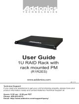
Power Supply
This power supply provides 500W of
power. Before turning on the main
switch located on the front panel of
the storage rack, turn on the power
switch of the power supply.
I
O
Power Switch
Fan
www.addonics.com Technical Support (M-F 8:30am - 6:00pm PST) Phone: 408-453-6212 Email: www.addonics.com/support/query/
Cable Connections
1. Attach the SATA hard drives (up to 5) to the SATA ports on the Hardware
Port Multiplier (HPM) using SATA cables. It is recommended to connect
drives to the SATA ports 1 to 5 successively.
2. To provide power to the HPM, connect a 4-pin floppy power cable from the
system power supply to the floppy power connector on the HPM.
3. Optional: Connect LEDs to the Activity & Error LED jumper block
Setting or Modifying the RAID Mode Using the JMicron
HW RAID Manager Utility Program:
1. For Windows users, install the JMicron HW RAID Manager located on the
SATA Controller CD. In the CD, go to Configuration Utilities > JMB393. This
manager can be use to create and monitor the status of the RAID volume.
It is recommended to use the default factory RAID DIP switch setting when
using the JMicron HW RAID Manager.
2. Modify the RAID mode on the 5-port HPM-XA using DIP switch
Recommended to be used on operating system without JMicron HW RAID
Manager support like Linux, Mac & Solaris. Windows users can also use the
procedure below.
Note: Steps A to D need to be performed each time the raid mode is modified.
a. Set the DIP switch as shown below.
b. Press the RAID setting button with a ball point pen.
c. While pressing the RAID setting button turn on the system power
where the HPM is connected. The buzzer will sound while holding the
RAID setting button. Release it after at least 5 seconds for hardware
initialization. A single beep will be heard to indicate initialization is
completed. The above steps act as a reset.
d. Power off the system power.
www.addonics.com
Phone: 408-573-8580
Fax: 408-573-8588
Email: http://www.addonics.com/sales/query/
CONTACT US
  • Page 1 1
  • Page 2 2
  • Page 3 3
  • Page 4 4
  • Page 5 5
  • Page 6 6
  • Page 7 7
  • Page 8 8
  • Page 9 9
  • Page 10 10
  • Page 11 11
  • Page 12 12

Addonics Technologies RTM4R5EU3 User manual

Category
HDD/SSD docking stations
Type
User manual
This manual is also suitable for

Ask a question and I''ll find the answer in the document

Finding information in a document is now easier with AI