WIA W55 2rd Wirefeeder Owner's manual
- Category
- Welding System
- Type
- Owner's manual

®
W55-40 Rev A
Weldmatic 2RD Wirefeeder
Operators Manual
Weldmatic Two Roll Drive
Enclosed Wirefeeder
Model No. W55-0, Iss B
05/07

Welding Industries of Australia
An ITW Company
ABN 18 004 547 111
Telephone: 1300 300 884
Facsimile: 1300 301 884
Email: [email protected]
www.welding.com.au

Contents
Section General information Page
Safe practices 2
1 Introduction 5
2 Receiving 5
3 Specifications 6
4 Wirefeeder Controls 6
5 Installation 8
6 Normal Welding Sequence 9
7 Basic Welding Information 9
8 General Maintenance 10
9 External Trouble Shooting 10
10 Wirefeeder Circuit Diagrams 11
11 Assembly and Parts Lists
11.1 Wirefeeder 12
11.2 Wirefeed Assembly 14
11.3 Gun and Cable Assembly 15
11.4 Composite Cable
Interconnecting Lead Kit 17
12 Warranty information 18
Weldmatic 2RD Wirefeeder
Model No W55-0, Iss B 05/07 1

2
Operators Manual
Quality • Reliability • Performance
Quality • Reliability • Performance
Safe practices when using
welding equipment
These notes are provided in the interests
of improving operator safety. They should
be considered only as a basic guide to Safe
Working Habits. A full list of Standards
pertaining to industry is available from
the Standards Association of Australia,
also various State Electricity Authorities,
Departments of Labour and Industry or
Mines Department and other Local Health
or Safety Inspection Authorities may have
additional requirements. Australian Standard
AS1674.2 provides a comprehensive guide to
safe practices in welding.
Eye protection
NEVER LOOK AT AN ARC WITHOUT
PROTECTION. Wear a helmet with
safety goggles or glasses with side shields
underneath, with appropriate filter lenses
protected by clear cover lens. This is a MUST
for welding, cutting, and chipping to protect
the eyes from radiant energy and flying
metal. Replace the cover lens when broken,
pitted, or spattered.
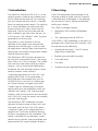
Recommended shade filter lens
Amps TIG MMAW MIG
Pulsed
MIG
0-100
10 9 10 12-13
100-150
11 10 10 12-13
150-200
12 10-11 11-12 12-13
200-300 13 11 12-13 12-13
300-400 14 12 13 14
400-500 — 13 14 14
500 + — — 14 14
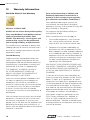
Read first
The information contained in this
manual is set out to enable you to
properly maintain your new equipment
and ensure that you obtain maximum
operating efficiency.
Please ensure that this information is
kept in a safe place for ready reference
when required at any future time.
When ordering spare parts, please
quote the model and serial number of
the wirefeeder and part number of the
item required. All relevant numbers are
shown in lists contained in this manual.
Failure to supply this information
may result in unnecessary delays in
supplying the correct parts.
Safety
Before this equipment is put into
operation, please read the Safe
Practices section of this manual.
This will help to avoid possible
injury due to misuse or improper
welding applications.
Plastic Handle on Wirefeeder
Please note that the handle fitted
to the Weldmatic 2RD wirefeeder is
intended for carrying the equipment by
hand only.
DO NOT use this handle for
suspending or mounting the
wirefeeder in any other manner.

Quality • Reliability • Performance
Weldmatic 2RD Wirefeeder
Model No W55-0, Iss B 05/07 3
Quality • Reliability • Performance
Burn protection
The welding arc is intense and visibly bright.
Its radiation can damage eyes, penetrate
light-weight clothing, reflect from light-
coloured surfaces, and burn the skin and
eyes. Burns resulting from gas-shielded arcs
resemble acute sunburn, but can be more
severe and painful.
Wear protective clothing - leather or heat
resistant gloves, hat, and safety-toe boots.
Button shirt collar and pocket flaps, and
wear cuffless trousers to avoid entry of
sparks and slag.
Avoid oily or greasy clothing. A spark may
ignite them. Hot metal such as electrode
stubs and work pieces should never be
handled without gloves.
Ear plugs should be worn when welding in
overhead positions or in a confined space.
A hard hat should be worn when others are
working overhead.
Flammable hair preparations should not be
used by persons intending to weld or cut.
Toxic fumes
Adequate ventilation with air is essential.
Severe discomfort, illness or death can
result from fumes, vapours, heat, or oxygen
depletion that welding or cutting may
produce. NEVER ventilate with oxygen.
Lead, cadmium, zinc, mercury, and beryllium
bearing and similar materials when welded
or cut may produce harmful concentrations
of toxic fumes. Adequate local exhaust
ventilation must be used, or each person in
the area as well as the operator must wear
an air-supplied respirator. For beryllium, both
must be used.
Metals coated with or containing materials
that emit fumes should not be heated unless
coating is removed from the work surface,
the area is well ventilated, or the operator
wears an air-supplied respirator.
Work in a confined space only while it is
being ventilated and, if necessary, while
wearing air-supplied respirator.
Vapours from chlorinated solvents can be
decomposed by the heat of the arc (or
flame) to form phosgene, a highly toxic
gas, and lung and eye irritating products.
The ultra-violet (radiant) energy of the arc
can also decompose trichlorethylene and
perchlorethylene vapours to form phosgene.
Do not weld or cut where solvent vapours
can be drawn into the welding or cutting
atmosphere or where the radiant energy
can penetrate to atmospheres containing
even minute amounts of trichlorethylene or
percholorethylene.
Fire and explosion prevention
Be aware that flying sparks or falling slag can
pass through cracks, along pipes, through
windows or doors, and through wall or floor
openings, out of sight of the operator. Sparks
and slag can travel up to 10 metres from the arc.
Keep equipment clean and operable, free of
oil, grease, and (in electrical parts) of metallic
particles that can cause short circuits.
If combustibles are present in the work
area, do NOT weld or cut. Move the work if
practicable, to an area free of combustibles.
Avoid paint spray rooms, dip tanks, storage
areas, ventilators. If the work can not be
moved, move combustibles at least 10
metres away out of reach of sparks and heat;
or protect against ignition with suitable and
snug-fitting fire-resistant covers or shields.
Walls touching combustibles on opposite
sides should not be welded on or cut. Walls,
ceilings, and floor near work should be
protected by heat-resistant covers or shields.

4
Operators Manual
Quality • Reliability • Performance
Quality • Reliability • Performance
Shock prevention
Exposed conductors or other bare metal
in the welding circuit, or ungrounded
electrically alive equipment can fatally shock
a person whose body becomes a conductor.
Ensure that the equipment is correctly
connected and earthed. If unsure have the
equipment installed by a qualified electrician.
On mobile or portable equipment, regularly
inspect condition of trailing power leads and
connecting plugs. Repair or replace damaged
leads.
Fully insulated electrode holders should be
used. Do not use holders with protruding
screws. Fully insulated lock-type connectors
should be used to join welding cable lengths.
Terminals and other exposed parts of
electrical units should have insulated knobs
or covers secured before operation.
A person acting as Fire Watcher must be
standing by with suitable fire extinguishing
equipment during and for some time after
welding or cutting if;
• Combustibles (including building
construction) are within 10 metres.
• Combustibles are further than 10 metres
but can be ignited by sparks.
• Openings (concealed or visible) in floors
or walls within 10 metres may expose
combustibles to sparks.
• Combustibles adjacent to walls, ceilings,
roofs, or metal partitions can be ignited
by radiant or conducted heat.
After work is done, check that area is free of
sparks, glowing embers, and flames.
A tank or drum which has contained
combustibles can produce flammable
vapours when heated. Such a container must
never be welded on or cut, unless it has first
been cleaned as described in AS.1674-2.
This includes a thorough steam or caustic
cleaning (or a solvent or water washing,
depending on the combustible’s solubility),
followed by purging and inerting with nitrogen
or carbon dioxide, and using protective
equipment as recommended in AS.1674-2.
Water-filling just below working level may
substitute for inerting.
Hollow castings or containers must be vented
before welding or cutting. They can explode.
Never weld or cut where the air may contain
flammable dust, gas, or liquid vapours.
If the supply cable is damaged
it must be replaced by the
manufacturer, their service agent
or a similarly qualified person.

Quality • Reliability • Performance
Weldmatic 2RD Wirefeeder
Model No W55-0, Iss B 05/07 5
Quality • Reliability • Performance
1 Introduction
Gas Metal Arc Welding (G.M.A.W.) is an arc
welding process where a consumable wire is
fed by motor driven feed rolls to a welding
gun, and where welding current is supplied
from the welding power source. The welding
arc is struck between the work piece and
the end of the wire, which melts into the
weld pool. The arc and the weld pool are
both shielded by gas flow from the gun, or
in the case of “self shielded” wires, by gases
generated by the wire core.
The process is very versatile in that by
selection of the correct wire composition,
diameter and shielding gas, it can be used
for applications ranging from sheet-metal to
heavy plate, and metals ranging from carbon
steel to aluminium alloys.
The Weldmatic 2RD has been designed to
be used with consumable wires in the range
from 0.6mm to 1.2mm diameter. The smaller
wire sizes are used when welding at lower
currents, such as sheet-metal applications.
Increasing the wire diameter permits higher
welding currents to be selected.
A common application of G.M.A.W. is for
welding Mild Steel. In this application, a
Mild Steel solid consumable wire such as
AUSTMIG ES6 is used with a shielding gas
of Carbon Dioxide, or Argon mixed with
Carbon Dioxide. Alternatively, Flux-cored
consumable wires are available in both gas
shielded, and ‘gasless’ self shielding types.
Stainless steel and Aluminium can be welded
with G.M.A.W. using the correct consumable
wire and shielding gas.
The Weldmatic 2RD wirefeeder has been
designed to feed a range of hard, soft, and
flux-cored wires for the G.M.A.W. process.
A compact motor with integral gear box is
coupled to a 2 roll drive assembly forming
the basic component of the wirefeeder. The
motor is controlled by an electronic speed
control which provides speed regulation and
compensation for supply voltage variations.
2 Receiving
Check the equipment received against the
shipping invoice to make sure the shipment
is complete and undamaged. If any damage
has occurred in transit, please immediately
notify your supplier.
The W55-0 package contains;
• Weldmatic 2RD Enclosed Wirefeeder
W55-0
• (This) operating manual W55-40.
If the W55-0, 2RD Wirefeeder is included in a
package with a Weldmatic MIG welder, it will
also containing the following;
• Interconnecting leads, 10 or 20 metre,
depending on package
• Bernard gun and cable assembly
• 10m work lead
• Gas hose
• Argon/mixed gas regulator/flowgauge.

6
Operators Manual
Quality • Reliability • Performance
Quality • Reliability • Performance
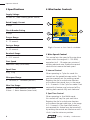
4 Wirefeeder Controls
3 Specifications
Supply Voltage
32 volts AC, (from welding power source)
Rated Supply Current
5 Amps
Circuit Breaker Rating
5 Amps
Pre-gas Range
0 - 1.2 seconds
Post-gas Range
0 - 2.5 seconds
Burnback Range
0 - 0.07 seconds
Start Speed
Normal or Creep (switchable)
Spool Sizes
5 kg, 15 kg
Wirespeed Range
0 - 190 RPM (0 - 18 Metres per min.)
Wire Size Range
0.6mm - 1.2mm diameter (solid wire)
0.9mm - 1.6mm diameter (cored wire)
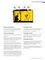
1 Wire Speed Control
This control sets the speed of the wire drive
motor within the range of 0 - 190 RPM,
equivalent to 0 - 18 metres per minute of
welding electrode wire. Rotate the control
clockwise to increase the feed speed.
2 Interval Control
When operating in Cycle Arc mode this
control sets the period between welds. The
spot time control sets the welding period.
Rotating the dial in a clockwise direction
will increase the interval time, in the range
0.4 – 5 seconds. If the Cycle Arc mode is not
required this feature may be turned off by
rotating both controls fully anti-clockwise.
3 Spot Time Control
When operating in Spot Weld mode,
this control will vary the spot weld time.
Rotating the dial in a clockwise direction
will increase the spot weld time, in the range
0.4 – 5 seconds. If the Spot Weld mode is
not required this feature may be turned off
by rotating the control anti-clockwise until it
‘clicks’ into the minimum position.
Fig 1.1 Controls on front face of wirefeeder
2
1
4
3

Quality • Reliability • Performance
Weldmatic 2RD Wirefeeder
Model No W55-0, Iss B 05/07 7
Quality • Reliability • Performance
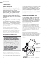
4 Power On Indicator
This indicator is illuminated when wirefeeder
is connected to a power source and the
power source is switched on.
5 Start Speed Switch
This switch controls the start up speed of the
wirefeeder:
‘Normal’ (up) is selected for immediate starts,
as required for tacking, short welds, etc. This
setting works well for most metals, but is
particularly suited to steel wires.
‘Creep’ (down) is selected when welding
more difficult materials such as aluminium or
stainless steel. In ‘Creep’ mode, the wire is
fed slowly until contact is detected and then
accelerated to full speed. Because the wire
comes into contact with the work slowly the
arc establishes smoothly.
This is followed by rapid acceleration so that
the arc does not flare up and damage the tip.
Even if an arc is not established, within one
second of the gun switch being operated the
wire feed accelerates to full welding speed.
5
6 8
Fig 1.2 Controls inside wirefeeder
7
6 Pre-gas Control
This control sets the time period of gas flow
before welding commences, and may be
adjusted from 0 - 1.2 seconds.
7 Post-gas Control
This control sets the time period of gas flow
after welding ceases, and may be adjusted
from 0 - 2.5 seconds.
8 Burnback Control
This control sets the time period that welding
voltage continues after the gun switch is
released, and wirefeed ceases, and may be
adjusted from 0 - 0.07 seconds.
When set correctly ‘Burnback’ prevents the
welding wire freezing in the weld pool at the
end of a weld.

8
Operators Manual
Quality • Reliability • Performance
Quality • Reliability • Performance
5 Installation
Remote Wirefeeder
The remote wirefeeder is connected to the
Weldmatic power source using the composite
cable interconnecting lead. Check all
connections are firmly made to ensure good
electrical contact, and to prevent gas leaks.
The Weldmatic 2RD wirefeeder is supplied
fitted with a W26-5/8 bottom roller which is
suitable for both 0.9mm and 1.2mm diameter
steel wire.
Fitting The Gun and Cable Assembly
The supplied Bernard gun/cable assembly is
equipped with a ‘Euro’ wirefeeder connector
which incorporates all required connection
points for welding current, shielding gas and
gun switch control.
To attach the gun/cable assembly to
the wirefeeder mechanism, engage the
mating parts of the male and female Euro
connectors, then rotate the locking ring
clockwise to firmly secure the connection.
Fitting the Consumable Wire
The quality of the consumable
wire greatly affects how reliably a
gas metal arc welder will operate.
For best results when welding
mild steel, we recommend quality
WIA AUSTMIG ES6. Dirty, rusty or
kinked wire will not feed smoothly
through the gun cable and will
cause erratic welding. Deposits
from the wire will clog the gun
cable liner requiring it to be
replaced prematurely.
Place the spool of welding wire onto the
spool holder. The location pin should mate
with a hole provided on the wire spool body.
Compression
screw
Top roller arm
Inlet guide
0.9
Groove size
Fit the spool retaining ‘R’ clip supplied. Check
the adjustment of the spool brake, which
should be set to prevent over run of the wire
spool at the end of a weld, without unduly
loading the wirefeed motor. The braking can
be adjusted by the Nyloc nut using a 15/16”
AF or 24mm socket wrench.
Feeding the Consumable Wire
At the wirefeeder, release the compression
screw and rotate the top roller arm to the
open position. The end of the welding wire
can now be passed through the inlet guide,
over the bottom driven roller, and into the
output wire guide tube.
Check that the drive roll groove is correct
for the wire in use. The appropriate size is
stamped on the visible side of the installed
roller. Check also that the correct size contact
tip is fitted at the gun end. Feed roller and
tip details are shown in Section 11 of this
manual.
Return the pressure arm to the closed
position and adjust the compression screw to
provide sufficient clamping of the drive roll
to achieve constant wirefeed. Do not over
tighten.

Quality • Reliability • Performance
Weldmatic 2RD Wirefeeder
Model No W55-0, Iss B 05/07 9
Quality • Reliability • Performance
6 Normal Welding Sequence
Weld Start
Closing the welding gun switch initiates this
sequence of events:
• The gas valve is energised and gas flow
commences and continues for any pre-
gas time set
• The power source contactor function
is initiated. Welding voltage is applied
between the work piece and the
consumable wire
• The wire drive motor is energised
• The wire touches the work piece, and the
arc is established.
Weld End
Releasing the gun switch initiates this
sequence of events:
• The wire drive motor is de-energised, and
is dynamically braked to a stop
• After a short pre-set period, known as
the ‘burn-back’ time, the Power-source
contactor function is released. This period
ensures that the consumable wire does
not ‘freeze’ in the weld pool
• At the completion of any post-gas time
set, the gas valve is de-energised and the
flow of shielding gas ceases.
Refer to the Weldmatic power source
Operators Manual for gas and weld setting
and gun position information.
7 Basic Welding Information

10
Operators Manual
Quality • Reliability • Performance
Quality • Reliability • Performance
3 Welding tip is free of obstructions such
as spatter build-up. Ream out the tip
bore with a suitable size oxy-tip cleaner.
Replace the welding tip as it becomes
worn;
4 Feed roll pressure is not excessive. The
pressure should be just sufficient to feed
the wire evenly. Excessive pressure will
deform the electrode wire and make
feeding more difficult;
5 Consumable wire spool holder rotates
smoothly and that the braking action is
not excessive. The spool should only have
sufficient braking to prevent over run
when the motor stops. This also may be
conveniently checked each time the wire
is replenished;
7 Welding wire is straight and free of
buckles or ‘waviness’. To check, remove
2 or 3 metres of wire from the spool.
Clamp one end in a vice or similar, then
holding the other end pull the wire out
straight. Look down the length of the
wire, any buckles will be obvious. Buckled
wire is extremely difficult to feed reliably
and should be replaced;
8 Welding wire is free of surface rust.
Replace if rust is evident.
Dust
Care should be taken to prevent excessive
build-up of dust and dirt within the welding
power source. It is recommended that at
regular intervals, according to the prevailing
conditions, the equipment covers be removed
and any accumulated dust be removed by the
use of dry, low pressure compressed air, or a
vacuum cleaner.
Wirefeed
In order to obtain the most satisfactory
welding results from the G.M.A.W. process,
the wirefeed must be smooth and constant.
Most causes of erratic wirefeed can be cured
by basic maintenance. Check that the:
1 Feed rolls are the correct size and type for
the wire in use. Check also that the drive
groove is aligned with the wire and that
the groove is not worn;
2 Gun cable liner is clear of dust and swarf
build-up. When replacement becomes
necessary, fit only the correct liner (see
page 15). The build-up of dust can be
minimised by regular purging of the liner
with dry compressed air. This may be
conveniently done each time the wire
spool is replaced;
8 General Maintenance
Before removing the equipment
cover, ENSURE that the equipment
is disconnected from the
mains power supply. When the
equipment is energised LETHAL
VOLTAGES are present.
9 External Trouble Shooting
Refer to the Weldmatic power
source Operators Manual for
trouble shooting tips. If these
checks do not identify the fault
condition, the equipment should be
returned to a WIA Service agent.
Phone 1300 300 884 for details of
your nearest service agent.

Quality • Reliability • Performance
Weldmatic 2RD Wirefeeder
Model No W55-0, Iss B 05/07 11
Quality • Reliability • Performance
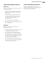
10 Wirefeeder Circuit Diagram
Fig 2 Wirefeeder Circuit Diagram
W41-12

12
Operators Manual
Quality • Reliability • Performance
Quality • Reliability • Performance
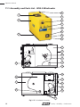
11.1 Assembly and Parts List - W55-0 Wirefeeder
14
15
16
17
13
12
18
Fig 3 2RD Wirefeeder Assembly
2
4
5
3
8
9
10
1
7
6
11
20
23
24
26
2
19
21
25
22

Quality • Reliability • Performance
Weldmatic 2RD Wirefeeder
Model No W55-0, Iss B 05/07 13
Quality • Reliability • Performance
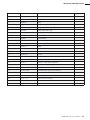
Item # Part # Description Qty
1 MZ208015 Handle Assembly 1
2 PAN017 Top / Side Panel 1
3 PAN022 Base 1
4 W41-0/2 Hinge Set, Right Hand 1
5 W41-0/1 Hinge Set, Left Hand 1
6 M0029 Adjusting Knob, Large 1
7 M0010 Adjusting Knob,Small 2
8 LST009 Label Set Complete 1
9 WF007 Euro Adapter 1
10 WF001-6 Euro Surround, Plastic 1
11 PAN020 Front Panel 1
12 PAN018 Door 1
13 PAN021 Back Panel 1
14 AM177 Spool Holder Assembly 1
15 AM133-3 R Clip 1
16 W29-1/20 Slam Action Catch 2
17 HF200-1/15 Plastic Foot 4
18 WF010 Motor & 2 Roll Drive Complete 1
19 CP34-36/2 Potentiometer, Wire Speed 1
20 W41-12N Wirefeed Control Printed Circuit Assembly 1
21 CP27-11/26 Potentiometer, Spot Time & Interval 2
22 M0031 PCB Support 2
23 CP101-0/18 Gas Valve 24 vdc 1
24 W11-11/1 Hose Tail for Gas Valve 2
25 AM298 Current Sensor Assembly 1
26 PAN026 Divider Panel 1

14
Operators Manual
Quality • Reliability • Performance
Quality • Reliability • Performance
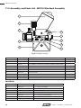
Fig 4 Wirefeed Assembly
1
5
3
4
2
6
7
8
Feed Rolls
Item # Part # Description Qty
1 WF001-1 Wirefeed Motor 1
2 WF001-5 Compression Screw 1
3 WF007 Euro Adapter (includes outlet guide fixing bolt and gas barb) 1
5 WF001-3 Feedplate 1
6 WF001-4 Top Roller Arm (includes top roller) 1
7 W26-0/13 Inlet Guide 1
8 W27-0/9 Retaining Screw 1
9 WF017 Euro Adapter bolt (included in WF007) 1
10 WF001-21 Outlet Guide Tube 1
Not shown W26-0/4 Drive Roller Key 1
Item # Part # Description
4 W26-1/8 0.8 + 1.0mm, Solid Wire
4 W26-2/8 0.9/1.0 + 1.2mm, Solid Wire (fitted)
4 W26-4/8 1.2 + 1.6mm, Solid Wire
4 W26-3/8 1.0 + 1.2mm, Aluminium Wire
4 W26-7/8 1.0 + 1.2mm, Flux Cored Wire
4 W26-6/8 1.2 + 1.6mm, Flux Cored Wire
4 W26-9/8 0.9 + 1.2mm, Flux Cored Wire
11.2 Assembly and Parts List - WF010 Wirefeed Assembly
10
9

Quality • Reliability • Performance
Weldmatic 2RD Wirefeeder
Model No W55-0, Iss B 05/07 15
Quality • Reliability • Performance
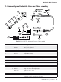
11.3 Assembly and Parts List - Gun and Cable Assembly
1
2
3
4
5
8
6
7
9
12b
12
12c
12a
11
10
15
13
14
Fig 5 BEQ3012AR7CE (390 amp) Gun and Cable Assembly
Item # Part # Description
1 BE4393
BE4392
Nozzle, copper, tapered (supplied)
Nozzle, brass, tapered
2 see ‘Tips’ (page 18) Contact Tip
3 BE4335-116 Gas Diffuser (Head)
4 BE4323 Cap
5 BEQT3-45 Body Tube Assembly
6 BE4313B End Fitting
7 BE4305 Cone Nut
8 BE1880155 Handle Kit (includes both halves, screws & posts)
9 BE5662 Trigger
10 BE2520042 Handle Spring
11 BE2520033 Strain Relief
12 BE1199E Euro Direct Plug Kit
Includes 12a BE4816 Euro Adaptor Nut
12b BE9165 Small “O” ring on gas nipple
12c BE4421 Large “O” ring at base of gas nipple
13 BE43115
BE43115X
BE44215
Steel Liner 0.9-1.2mm
Nylon Liner 0.9-1.2mm
Steel Liner 1.6mm
14 BE2520069 Rigid Strain Relief
15 BE1983 Rear Cone Nut Repair Kit (includes: jacket clamp, conduit clamp, cone nut,
end fitting, nipple, spacer & butt connectors)

16
Operators Manual
Quality • Reliability • Performance
Quality • Reliability • Performance
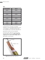
To replace liner: Disconnect gun/cable
assembly at the Euro adaptor. Remove nozzle
(1) and head (3). Withdraw old liner from
the wirefeeder end. Insert new liner and refit
gun/cable assembly to the wirefeeder.
At the gun end, compress the liner within
the gun cable, then cut it one contact tip
length past the end of the body tube (5).
Refit head, tip and nozzle.
Cut Here
Compress Liner
Tips
Wire diameter Part #
0.6mm BE7497
0.8mm BE7488
0.9mm BE7489
1.0mm BE7496
1.2mm BE7490
1.3mm BE7498
1.6mm BE7491
2.0mm BE7492
2.4mm BE7493
2.8mm BE7494
3.2mm BE7495
Fig 6 Replacing the gun cable liner

Quality • Reliability • Performance
Weldmatic 2RD Wirefeeder
Model No W55-0, Iss B 05/07 17
Quality • Reliability • Performance
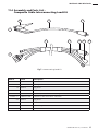
11.4 Assembly and Parts List -
Composite Cable Interconnecting Lead Kit
Item # Part # Description
1 Work Lead
Includes 1.1 CABW50 Welding Cable 50mm
2
1.2 WGEC4 Plug, Dinse
1.3 WGWC2 Work Clamp
2 10m Composite Cable Interconnecting Lead
Includes 2.1 CABW50COMP Composite Cable with 50mm
2
Weld Flex
2.2 WGEC4 Plug, Dinse
2.3 WG62513 Gas Hose 5mm
2.4 AM112-3/1 Control Plug
2.5 WGAC23 5/8” UNF Gas Nut and Tail
Fig 7 Interconnecting Lead Kit
1
1.3
1.1 1.2
2
2.1 2.3 2.2 2.4
2.5

18
Operators Manual
Quality • Reliability • Performance
Quality • Reliability • Performance
12 Warranty Information
Parts and workmanship on Weldarc and
Weldmatic equipment are covered for a
period of 3 years (except for gas regulator,
gun cable and consumables listed below.)
Items replaced under original warranty are
warranted for the remainder of the original
equipment warranty, or for a period of ninety (90)
days, whichever is the greater.
Gas regulator and gun/cable assembly are
warranted for 90 days.
WIA’s Limited Warranty shall not apply to:
1 Consumable components; such as contact
tips, cutting nozzles, contactors, brushes,
relays or parts that fail due to normal wear.
2 Equipment that has been modified by any
party other than WIA, or equipment that has
been improperly installed, improperly operated
or misused based upon industry standards, or
equipment which has not had reasonable and
necessary maintenance, or equipment which
has been used for operation outside of the
specifications for the equipment.
WIA PRODUCTS ARE INTENDED FOR PURCHASE
AND USE BY COMMERCIAL / INDUSTRIAL USERS
AND PERSONS TRAINED AND EXPERIENCED
IN THE USE AND MAINTENANCE OF WELDING
EQUIPMENT.
In the event of a warranty claim covered by this
warranty, the exclusive remedies shall be, at WIA’s
option: (1) repair; or (2) replacement; or, where
authorised in writing by WIA in appropriate cases,
(3) the reasonable cost of repair or replacement by
an authorised WIA service agent; or (4) payment
of or credit for the purchase price (less reasonable
depreciation based upon actual use) upon return
of the goods at customer’s risk and expense.
WIA’s option of repair or replacement will be
F.O.B. Factory at Melrose Park, Adelaide, or
F.O.B. at a WIA authorised service facility as
determined by WIA. Therefore no compensation
or reimbursement for transportation costs of any
kind will be allowed.
WIA Gold Shield 3 Year Warranty
Effective 1st March 2005
At WIA, we are serious about product quality.
Every new Weldmatic and Weldarc machine
comes fully backed by the WIA ‘Gold
Shield 3 Year Warranty’, covering parts and
workmanship, so you can be guaranteed
you’re buying reliability and performance.
This limited warranty supersedes all previous WIA
(Welding Industries of Australia) warranties and is
exclusive with no other guarantees or warranties
expressed or implied.
Limited Warranty
Subject to the terms and conditions below, WIA
warrants to its original retail purchaser that new
WIA equipment sold after the effective date of this
limited warranty is free of defects in material and
workmanship at the time it is shipped by WIA.
THIS WARRANTY IS EXPRESSLY IN LIEU OF
ALL OTHER WARRANTIES, EXPRESS OR
IMPLIED, INCLUDING THE WARRANTIES OF
MERCHANTABILITY AND FITNESS.
Within the warranty periods listed below, WIA
will repair or replace any warranted parts or
components that fail due to such defects in
material or workmanship. WIA must be notified
in writing within thirty (30) days of such defect
or failure, at which time WIA will provide
instructions on the warranty claim procedures to
be followed.
WIA shall honour warranty claims on warranted
equipment in the event of such a failure within
the warranty time periods. All warranty time
periods start on the date that the equipment was
delivered to the original retail purchaser, or 18
months after the equipment date of manufacture,
whichever is the earlier.
Page is loading ...
-
 1
1
-
 2
2
-
 3
3
-
 4
4
-
 5
5
-
 6
6
-
 7
7
-
 8
8
-
 9
9
-
 10
10
-
 11
11
-
 12
12
-
 13
13
-
 14
14
-
 15
15
-
 16
16
-
 17
17
-
 18
18
-
 19
19
-
 20
20
-
 21
21


WIA W55 2rd Wirefeeder Owner's manual
- Category
- Welding System
- Type
- Owner's manual
Ask a question and I''ll find the answer in the document
Finding information in a document is now easier with AI
Related papers
-
WIA Weldmatic 150 Owner's manual
-
WIA Weldmatic 175 Owner's manual
-
-
-
-
-
-
-
-
Other documents
-
Clarke Weld 215TE Specification
-
Multibrackets 7 350 073 732 067 User manual
-
 SUN GLOW Roller Shades Operating instructions
-
Rac RAC-HP101 Assembly Manual
-
Blue Wave NE4375 User manual
-
ESAB FABRICATOR WELDER User manual
-
ESAB Firepower MST 140i 3-IN-1 Multi Process Welding System User manual
-
ESAB FABRICATOR® 252i 3-IN-1 Multi Process Welding Systems User manual
-
-
