Appliances Connection Picks SHARP SDW6757ES Installation guide

Category
Dishwashers
Type
Installation guide
1
Dishwasher: SDW6757ES
INSTALLATION MANUAL
BEFORE YOU BEGIN READ THESE
INSTRUCTIONS COMPLETELY AND
CAREFULLY.
IMPORTANT – Observe all governing codes and ordinances.
1
Note to Installer – Be sure to leave these instructions for the
consumer’s and local inspector’s use.
2
Note to Consumer – Keep these instructions with your Owner’s
Manual for future reference.
3
Skill Level – Installation of this dishwasher requires basic
mechanical and electrical skills. Proper installation is the
responsibility of the installer. Product failure due to improper
installation is not covered under the SHARP Consumer Limited
Wa r rant y.
4
Completion Time – 1 to 3 Hours. New installations require more
time than replacement installations.
IMPORTANT – The dishwasher MUST be installed to allow for
future removal from the enclosure if service is required.
If you received a damaged dishwasher, you should immediately
contact your dealer or builder.
FOR YOUR SAFETY - Read and observe all CAUTIONS
and WARNINGS shown throughout these instructions. While
performing installations described in this booklet, gloves, safety
glasses or goggles should be worn.
WARNING
To reduce the risk of electric shock, re, or injury to
persons, the installer must ensure that the dishwasher
is completely enclosed at the time of installation.
READ CAREFULLY.
SAVE THESE INSTRUCTIONS.
If you have an installation problem, contact your dealer or installer.
You are responsible for providing adequate electrical, exhausting
and other connecting facilities.
1
INSTALLATION PREPARATION
PARTS SUPPLIED:
NAME & DESCRIPTIONS QT Y. PARTS
Flat Head Wood Screws to
secure dishwasher to underside of
countertop (in literature package)
4
Screw Type Hose Clamps 1
Drain Hose 1
Top Mounting Clips 2
MATERIALS REQUIRED:
NAME & DESCRIPTIONS QT Y. PARTS
Ferrule, Compression Nut and
90° Elbow (
3
/
8
" NPT external
thread on one end, opposite end
sized to t water supply)
1
Thread Seal Tape 1
UL Listed Wire Nuts 3
2
INSTALLATION PREPARATION
MATERIALS FOR NEW INSTALLATIONS
ONLY:
NAME & DESCRIPTIONS PARTS
Air Gap for Drain Hose, if required
Waste Tee for House Plumbing, if
applicable
Electrical Cable or Power Cord,
if applicable
Screw Type Hose Clamps
Strain Relief for Electrical Connection
Hand Shut-off Valve
Hot Water Line
3
/
8
" minimum Copper
Coupler for Extending Drain Line, if
applicable
TOOLS REQUIRED:
NAME & DESCRIPTIONS PARTS
Phillips Head Screwdriver
5
/
16
" and
1
/
4
" Nut Driver
6" Adjustable Wrench
Level
Carpenter's Square
Measuring Tape
Safety Glasses
Bucket to catch water when
ushing the line
Gloves
FOR NEW INSTALLATIONS ONLY:
NAME & DESCRIPTIONS PARTS
Tubing Cutter
Drill and Appropriate Bits
Hole Saw Set
3
INSTALLATION PREPARATION
CABINET DIMENSIONS
The rough cabinet opening must be at least 24" deep. The opening
should be 35" maximum height.
The dishwasher must be installed so that the drain hose is no more
than 10 feet in length for proper drainage.
The dishwasher must be fully enclosed on the top, sides and back,
and must not support any part of the enclosure.
24"
34"
min.
to
35"
max**
24"
min.
90˚
90˚
3
1
/
2
"
3"
3
1
/
2
"
1
3
/
4
"
1
3
/
4
"
1
3
/
4
"
1
3
/
4
"
3"
18"
FIGURE A
CLEARANCES
When installed in a corner, allow 2" minimum clearance between
dishwasher and adjacent cabinets, walls or other appliances. Allow
25
5
/
8
" minimum clearance from the front of the dishwasher for door
opening. See Figure B.
Countertop
Dishwasher
Clearance for Door
Opening 2" Minimum
25
5
/
8
"
FIGURE B
DRAIN REQUIREMENTS
Follow local codes and ordinances.
Do not exceed 10 feet in distance to drain.
Do not connect drain lines from other devices to the dishwasher
drain hose.
Dishwasher must be connected to waste line with an air gap (not
supplied) or 32" minimum high drain loop, depending on local
codes and ordinances, to prevent back ow into the dishwasher.
Air gap must be used if waste tee or disposer connection is less
than 18" above the floor to prevent siphoning.
DRAIN PREPARATION
The type of drain installation depends on answers to the following
questions:
Do local codes or ordinances require an air gap?
Will waste tee or disposer connection be less than 18" above
the oor?
Will installation have a drain loop less than 32" above the oor?
If the answer to ANY of the 3 questions above is YES, Method 1
MUST be used. Otherwise, either Method 1 or Method 2 may be used.
CAUTION
An air gap MUST BE USED if the drain hose is
connected to waste tee or disposer lower than 18" above the oor.
Failure to provide the proper drain connection height with air gap
or 32" minimum high drain loop, will result in improper draining
of the dishwasher. Figure C or Figure D.
Method 1 – Air Gap with Waste Tee or Disposer
FIGURE C
Method 2 – High Drain with Waste Tee or Disposer
Provide a method to attach drain hose to underside of countertop.
18"
Min.
32"
Min.
32"
Min.
18"
Min.
FIGURE D
Install waste tee or disposer and air gap according to manufacturer’s
instructions.
CABINET PREPARATION
Drill a 1
1
/
2
" diameter hole in the cabinet wall within the shaded
areas shown in Figure A for the drain hose connection. The hole
should be smooth with no sharp edges.
4
PREPARE ELECTRICAL WIRING
WARNING
FOR PERSONAL SAFETY: Remove house fuse or
open circuit breaker before beginning installation.
Do not use an extension cord or adapter plug with
this appliance.
ELECTRICAL REQUIREMENTS
This appliance must be supplied with 120V, 60 Hz. It must be
connected to an individual properly grounded branch circuit and
protected by a 15 or 20 ampere circuit breaker or time delay fuse.
Wiring must be 2-wire with ground.
If the electrical supply does not meet the above requirements, call
a licensed electrician before proceeding.
GROUNDING INSTRUCTIONS – CABLE DIRECT
This appliance must be connected to a grounded metal, permanent
wiring system, or an equipment grounding conductor must be run
with the circuit conductors and be connected to the equipment
grounding terminal or lead on the appliance.
GROUNDING INSTRUCTIONS – POWER CORD
MODELS
This appliance must be grounded. In the event of a malfunction
or breakdown, grounding will reduce the risk of electric shock by
providing a path of least resistance for electric current. The plug must
be plugged into an appropriate outlet that is installed and grounded
in accordance with local codes and ordinances.
WARNING
The improper connection of the equipment grounding
conductor can result in a risk of electric shock. Check
with a qualied electrician or service representative if
there is doubt that the appliance is properly grounded.
White
24"
From Wall
Ground
Black
1
1
/
2
" Dia.
Hole (Max.)
2
1
/
2
" - 3
1
/
2
"
From
Cabinet
FIGURE E
INSTALLATION INSTRUCTIONS
CABINET PREPARATION & WIRE ROUTING
The wiring may enter the opening from either side, rear or the
oor within the shaded area.
Cut a 1
1
/2" maximum diameter hole to allow the electrical cable.
The hole must be free of sharp edges. If the cabinet wall is metal,
the hole edge must be covered with a bushing.
Cable direct connections may pass through the same hole as
the drain hose and hot water line, if convenient. If cabinet wall
is metal, the hole edge must be covered with a bushing. NOTE:
Power cords with plug must pass through a separate hole.
ELECTRICAL CONNECTION TO DISHWASHER
Electrical connection is on the right front of dishwasher.
For cable direct connections, the cable must be routed as shown in
Figure E. Cable must extend a minimum of 24" from the rear wall.
For power cord connections, install a 3-prong grounding type
receptacle. The power supply receptacle for the appliance shall
be installed in a cabinet or on a wall adjacent to the under counter
space in which the appliance is to be installed.
PREPARE HOT WATER LINE
The line may enter from either side, rear or oor within the shaded
area shown in Figure F.
The line may pass through the same hole as the electrical cable
and drain hose. Or, cut an additional 1
1
/
2
" diameter hole to
accommodate the water line. If a power cord with plug is used,
water line must not pass through power cord hole.
R U V H U Y L F H U H S U H V H Q W D W L Y H L I
1
/3
1
/3"
From Cabinet
Shut-off
Valve
18" From Wall
3" From Floor
Cabinet Face
Hot
Water
Supply
Line
Power
Cable
1
/
3
1
/
3
"
1
/2
1
/2"
5
INSTALLATION INSTRUCTIONS
WATER LINE CONNECTION
Turn off the water supply.
Install a hand shut-off valve in an accessible location, such as
under the sink. (Optional, but strongly recommended and may
be required by local codes.)
Water connection is on the left side of the dishwasher. Install the
hot water inlet line, using no less than
3
/
8
" O.D. copper tubing.
Route the line as shown in Figure F and extend forward at least
18" from rear wall.
Adjust water heater for 120˚F to 150˚F temperature.
Flush water line to clean out debris.
The hot water supply line pressure must be 20 - 120 PSI.
CAUTION
Opening the door will cause the
dishwasher to tip forward. Do not open the door
until you are ready to install the dishwasher.
If it is necessary to open the door, hold the top of
the dishwasher securely with one hand and hold
the door with the other hand.
STOP
BEFORE YOU BEGIN
Locate and set aside the package containing 2 Phillips head
countertop mounting screws and 2 additional toe kick screws (located
in the literature package).
STEP 1: CHECK DOOR BALANCE
To check the door balance, hold the top of the dishwasher rmly.
Open the door slowly, if the door drops when released, increase
spring tension. If the door closes when released, decrease tension.
Adjust both door springs to the same tension.
Continue moving the spring pin until door is balanced.
STEP 2: ADJUST LEVELING LEGS
Move the dishwasher close to the installation location and lay it
on its back.
Measure installation height and dishwasher height. Extend
leveling legs out from the dishwasher base,
1
/
4
" less than
installation height.
STEP 3: REMOVE TOE KICK
Remove the 2 toe kick screws. Lift off the 1 piece toe kick.
Adjust
Installation
Height
Increase
Decrease
6
INSTALLATION INSTRUCTIONS
STEP 4: INSTALL POWER CORD
Skip this step if dishwasher will be direct wired. Use power cord
kit WX09X70910 available for purchase from an authorized Sharp
parts dealer. The power cord and connections must comply with
local codes and ordinances.
Recommended power cord length is 54" minimum and 64"
maximum.
Green Wire to
Green Wire (Ground)
Black Wire to
Black Wire (Hot)
White Wire to
White Wire (Neutral)
Remove
Junction Box
Cover
Connect incoming power cords: white (or ribbed) to dishwasher
white, black (or smooth) to black and ground to dishwasher green
wire. Use cUL/UL listed wire nuts of appropriate size.
Replace junction box cover. Be sure wires are not pinched under
the cover.
STEP 5: INSTALL 90˚ ELBOW
Wrap 90˚ elbow with thread seal tape. Do not use plumber's putty.
Install a 90˚ elbow onto the water valve.
Do not over tighten 90° elbow; water valve bracket could bend or
water valve tting could break.
Position the end of the elbow to face the bottom right of the
dishwasher.
STEP 6: INSTALL DRAIN HOSE
Install the screw type hose clamps to the drain hose.
Connect the drain hose to the drain hose installation hose, then
tighten the screw type hose.
The Drain Hose
Installation Hole
STEP 7: INSERT DRAIN HOSE THROUGH CABINET
Upright the dishwasher and position in front of the opening. Insert
drain hose into cabinet wall hole. If a power cord is used, guide
the end through a separate hole.
Power Cord
(if used)
House
Wiring
Drain
Hose
Water
Line
Insulation
Blanket
Maximum
Drain Hose
Length 10'
TIP: Position water line and house wiring on the oor to avoid
interference with base of dishwasher.
7
STEP 10: LEVEL DISHWASHER
WARNING
Dishwasher must be level for proper dish rack
operation and wash performance.
Place level on door and rack track inside the tub as shown to check
that the dishwasher is level.
Check Level
Front to Back
Check Level
Side to Side
Level the dishwasher by adjusting the four leveling legs
ind ividu ally.
Turn Legs
to Adjust
TIP: Pull lower rack out, about halfway. Make sure the rack does
not roll forward or back into dishwasher. If the rack rolls in either
direction, the dishwasher must be leveled again.
If the door hits the tub, the dishwasher is not installed correctly.
Adjust leveling legs to align door to tub.
INSTALLATION INSTRUCTIONS
STEP 8: SLIDE DISHWASHER PARTIALLY INTO
CABINET
DO NOT PUSH AGAINST FRONT PANEL WITH KNEES.
DAMAGE WILL OCCUR.
Slide dishwasher into the opening a few inches at a time.
As you proceed, pull the drain hose through the opening under the
sink. Stop pushing when the dish washer is a few inches forward
of adjacent cabinetry.
Make sure drain hose is not kinked under the dish washer and
there is no interference with the water line, wiring or any other
component.
STEP 9: POSITION DISHWASHER UNDER
COUNTERTOP
Make sure that wires are secure under the dishwasher and not
pinched or in contact with door springs or other dishwasher
components.
TIP: Check tub insulation blanket, if equipped. It should be
positioned so it is not bunched up or interfering with door springs.
Check by opening and closing the door.
Push dishwasher into cabinet. The front corners of the dishwasher
door should be ush with cabinet doors. Be careful not to dent
front panel with knees or damage countertop or cabinets with
dishwasher parts.
8
STEP 11: SECURE DISHWASHER TO CABINET
METHOD 1 - To install using Top Mount Cabinet Clips:
Depending on the depth of the cabinet, the Top Mount Clips have a
break-off point that can be removed if necessary.
NOTE: Install Top Mount Clips before unit is installed into the
cabinet. Insert the installation brackets to the front top slots of the
dishwater. (See image below.)
The dishwasher must be secured to the countertop. Position the
dishwasher so that the tub ange aligns with the front face of the
cabinet frame.
IMPORTANT
Make sure the dishwasher is centered in the opening
and there is no interference with adjacent cabinets when opening or
closing the door.
Align Tub
Flange
to Front
Face of
Cabinet
Frame
Fasten the dishwasher to the underside of the countertop with the 2
Phillips screws provided.
INSTALLATION INSTRUCTIONS
METHOD 2 – To install on the side boards:
In case counter tops are made of marble, granite, or other hard
materials that could not be drilled, use the installation method below.
Open the door and remove the tub caps on both sides of the tub.
Install screws through the dishwasher side holes to the wall of the
cabinet. Reinstall tub caps.
IMPORTANT
Drive screws straight and ush. Protruding screw
heads will scratch the top of the control panel and can interfere with
the door's ability to close. If the gap is less than
3
/8" between control
panel and the screws, method 2 is recommended.
STEP 12: CONNECT WATER SUPPLY
Connect water supply line to 90° elbow.
Slide compression nut, then ferrule over end of water line.
Insert water line into 90° elbow.
Slide ferrule against elbow and secure with compression nut.
90° Elbow
Hot Water
Supply Line
Compression
Nut
Ferrule
IMPORTANT
Make sure the door spring does not rub or contact the
ll hose or water supply line. Test by opening and closing the door.
Reroute the lines if a rubbing noise or interference occurs.
9
INSTALLATION INSTRUCTIONS
STEP 13: CONNECT DRAIN LINE
FOLLOW ALL LOCAL CODES AND ORDINANCES.
The drain hose molded end will fit
5
/8",
3
/4" or 1" diameter
connections on the air gap, waste tee or disposer. Cut on the marked
line as required for your installation.
1" 3/4" 5/8"
Cutting Lines
IMPORTANT: Do not cut corrugated portion of hose
If a longer drain hose is required, add up to 42" of length for a
total of 10 feet to the factory installed hose. Use
5
/8" or
7
/8" inside
diameter hose and a coupler to connect the two hose ends. Secure
the connection with hose clamps.
Hose Clamp
Hose Clamp
Coupler
Secure the drain hose to the air gap, waste tee or disposer with
clamps.
NOTE: TOTAL DRAIN HOSE LENGTH MUST NOT EXCEED
10 FEET FOR PROPER DRAIN OPERATION.
DRAIN LINE INSTALLATION
Connect drain line to air gap, waste tee or disposer using either
previously determined method.
METHOD 1 Air gap with waste tee or disposer
Waste Tee Installation Disposer Installation
METHOD 2 – High drain loop with waste tee or disposer
Waste Tee Installation
18"
Min.
18"
Min.
32"
Min.
32"
Min.
Fasten to underside
of countertop
Disposer Installation
Fasten to underside
of countertop
Remove
Hopper
Plug
IMPORTANT
When connecting drain line to
disposer, make sure that the drain plug has been
removed. DISHWASHER WILL NOT DRAIN
IF PLUG IS LEFT IN PLACE.
TIP: Avoid unnecessary service call charges. Always be sure
disposer drain plug has been removed before attaching dishwasher
drain hose to the disposer.
STEP 14: CONNECT POWER SUPPLY
Skip this step if equipped with power cord. Verify that power is
turned off at the source.
Remove junction box cover “A.
Locate the three dishwasher wires (white, black and green) with
stripped ends. Insert dishwasher wires through the small hole in
the junction box “B”.
Secure house wiring to the bottom of the junction box with a
strain relief “C.
Use wire nuts to connect incoming ground to green, white to
white and black to black “D”.
Replace junction box cover “E”. Be sure that wires are not pinched
under the cover.
A. Remove
Junction
Box Cover
B. Check that White, Black
and Green Dishwasher
Wires are threaded through
hole in back
C. Insert Power Cord Wires through
Strain Relief and tighten
D. Use UL Listed
Wire Nuts
E. Replace Junction
Box Cover
Black
White
Ground
WARNING
If house wiring is not 2-wire with ground, a ground
must be provided by the installer. When house
wiring is aluminum, be sure to use cUL/UL Listed
antioxidant compound and aluminum-to-copper
connectors.
10
INSTALLATION INSTRUCTIONS
STEP 15: PRE-TEST CHECKLIST
Review this list after installing your dishwasher to avoid charges
for a service call that is not covered by your warranty.
Check to be sure power is OFF.
Open door and remove all foam and paper packaging.
Locate the Owner’s Manual in the literature package.
Read the Owner’s Manual for operating instructions.
Check door opening and closing. If door does not open and close
freely or tends to fall, check spring adjustments. See Step 1.
Be sure that wiring is secure under the dishwasher, not pinched
or in contact with door springs or other components. See Step 9.
Check door alignment with tub. If door hits tub, level dishwasher.
See Step 10.
Pull lower rack out, about halfway. Make sure it does not roll
back or forward on the door. If the rack moves, adjust leveling
legs. See Step 10.
Check door alignment with cabinet. If door hits cabinet, reposition
or relevel dishwasher. See Step 10.
Verify water supply and drain lines are not kinked or in contact
with other components. Contact with motor or dishwasher frame
could cause noise. See Step 8.
Turn on the sink hot water faucet and verify water temperature.
Incoming water temperature must be between 120°F and 150°F.
A minimum of 120°F temperature is required for best wash
performance. See “Prepare Hot Water Line,” page 4.
Add 2 liters of water to the bottom of the dishwasher to lubricate
the pump seal.
Turn on water supply. Check for leaks. Tighten connections if
needed.
Remove protective lm if present from the control panel and door.
STEP 16: DISHWASHER WET TEST
Turn on power supply (or plug power cord into outlet, if equipped).
Turn on the dishwasher (please refer to the Operation Manual
for instructions).
Close door, select RINSE ONLY cycle and press START/
CANCEL.
Be sure that water enters the dishwasher. If water does not enter
the dishwasher, ensure that water and power are turned on.
Check for leaks under the dishwasher. If a leak is found, turn
power supply off, then tighten connections. Restore power after
leak is corrected.
Check for leaks around the door. A leak around the door could be
caused by the door rubbing or hitting against adjacent cabinetry.
Reposition the dishwasher if necessary. See Step 9.
When the dishwasher is draining, check the drain lines. If leaks
are found, turn power off at the breaker and correct plumbing as
necessary. Restore power after corrections are made. See Step 12.
Open dishwasher door and make sure most of the water has
drained. If not, check that disposer plug has been removed and/
or air gap is not plugged. See Step 13. Also check drain line for
kinking.
Run the dishwasher through another ll and drain cycle. Check
for leaks and correct if required.
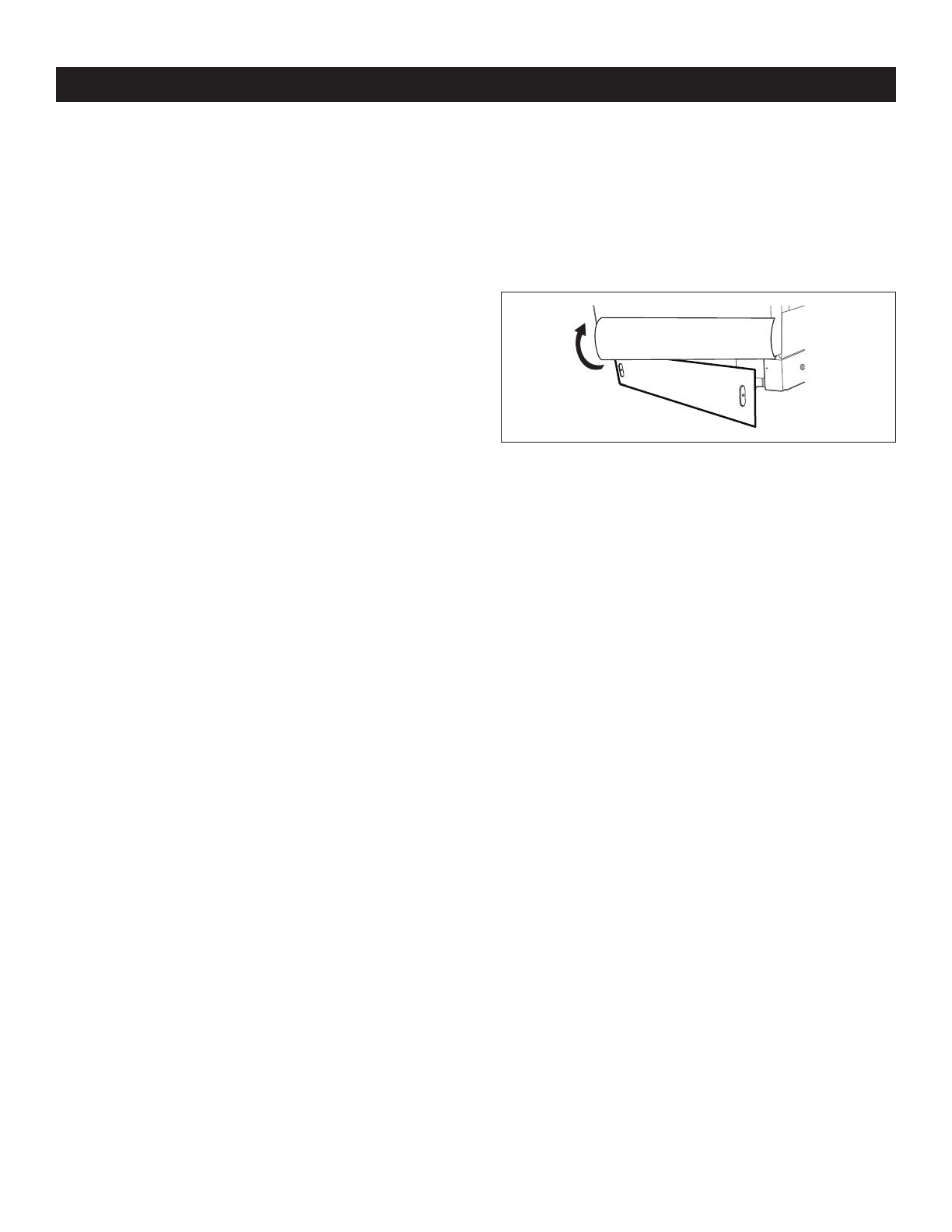
STEP 17: REPLACE TOE KICK
Place 1-piece toe kick against the legs of the dishwasher. The slots
should align with toe kick bracket screw holes. Allow the toe kick
to touch the oor. Install the toe kick screws.
STEP 18: LITERATURE
Be sure to leave complete literature package and installation
instructions with the consumer.
SHARP ELECTRONICS CORPORATION100 Paragon Drive Montvale, New Jersey 07645 USA
Sep 23, 2019
1 / 1

Appliances Connection Picks SHARP SDW6757ES Installation guide

Category
Dishwashers
Type
Installation guide

Ask a question and I''ll find the answer in the document

Finding information in a document is now easier with AI

Ask the document