Real Fyre G45-2 Owner's manual

Category
Fireplaces
Type
Owner's manual

This manual is also suitable for

Real Fyre G45-2 SS Outdoor is a natural gas burner system designed for use in see-through solid-fuel burning fireplaces. It features an unregulated burner system, making it easy to adjust the flame height and intensity to create a realistic fire look. With a variety of sizes available, the Real Fyre G45-2 SS Outdoor can accommodate different fireplace dimensions, ranging from 25 to 66 inches in width. The burner system includes a damper clamp to prevent accidental closure of the damper, ensuring proper ventilation.

Real Fyre G45-2 SS Outdoor is a natural gas burner system designed for use in see-through solid-fuel burning fireplaces. It features an unregulated burner system, making it easy to adjust the flame height and intensity to create a realistic fire look. With a variety of sizes available, the Real Fyre G45-2 SS Outdoor can accommodate different fireplace dimensions, ranging from 25 to 66 inches in width. The burner system includes a damper clamp to prevent accidental closure of the damper, ensuring proper ventilation.

1
L-A2-297
REV 0 -1407291445
Owner’s
Manual
ROBERT H. PETERSON CO. • 14724 East Proctor Avenue • City of Industry, CA 91746ROBERT H. PETERSON CO. • 14724 East Proctor Avenue • City of Industry, CA 91746
Important: Read this manual carefully before starting installation of the log set.
INSTALLER: Leave this manual with the appliance.
CONSUMER: Retain this manual for future reference.
This appliance is designed as an attended
appliance. Adults must be present when the
unit is operating. DO NOT leave this unit burning
when unattended. If this product is left burning
unattended it may cause damage or serious
injury.
WARNING
Improper installation, adjustment, alteration,
service, or maintenance can cause injury or
property damage. Read the installation, operating
and maintenance instructions thoroughly before
installing or servicing this equipment.
Do not store or use gasoline or other
ammable vapors and liquids in the vicinity
of this or any other appliance.
An LP-cylinder shall not be stored in the
vicinity of this or any other appliance.
WHAT TO DO IF YOU SMELL GAS:
Do not try to light any appliance.
Do not touch any electrical switch; do
not use any phone in the building.
Immediately call the gas supplier from
a neighbor’s phone and follow the gas
supplier’s instructions.
If you cannot reach the gas supplier,
call the fi re department.
WARNING
If the information in this manual is not followed
exactly, a fi re or explosion may result, causing
property damage, personal injury, or loss of life.
Installation and service must be performed
by an NFI Certifi ed or other qualifi ed
professional installer, service agency, or
the gas supplier.
CODE AND SUPPLY REQUIREMENTS
This outdoor burner must be installed in accordance
with local codes and ordinances, or in the absence of
local codes, with the latest National Fuel Gas Code,
ANSI Z223.1.
G45 STAINLESS STEEL BURNER FOR OUTDOOR USE ONLY
Burner systems:
G45-2-16/19-SS
G45-2-18/20-SS
G45-2-24-SS
G45-2-30-SS
G45-2-36-SS
G45-2-42-SS
G45-2-48-SS
G45-2-60-SS
Unregulated burner
system,
for use with natural
gas only
FOR INSTALLATION IN
SEE-THRU SOLID-FUEL
BURNING FIREPLACES
2
L-A2-297
REV 0 -1407291445
TABLE OF CONTENTS
SAFETY INFORMATION
1. Children and adults should be alerted to the hazards of high surface temperatures and
should stay away to avoid burns or clothing ignition.
2. Young children should be carefully supervised when they are in the area of the appliance.
3. Clothing or other fl ammable materials should not be placed on or near the appliance.
4. Any guard or other protective device removed for servicing the appliance must be
replaced prior to operating the appliance.
5. Installation and repair must be done by a qualifi ed professional service person. The
appliance must be inspected before use and at least annually by a qualifi ed professional
service person. More frequent cleaning may be required as necessary.
6. Solid fuels shall not be burned in a fi replace where this appliance is installed.
7. Keep the appliance area clear and free from combustible materials, gasoline and other
ammable vapors and liquids.
8. The burner assembly must be replaced prior to the appliance being put into operation
if it is evident that the burner assembly is damaged. Contact your local dealer for
replacement parts.
9. A replace screen must be in place when the system is burning. Provisions for adequate
combustion air must be maintained. Unless other provisions for combustion air are
provided, the screen shall have an opening(s) for introduction of combustion air.
Combustion air is adequate when all fl ames curl into the fi replace and away from the
screen. When a glass fi replace enclosure (door) is used, leave the doors fully open when
the system is in operation.
SAFETY INFORMATION 2
PARTS LIST 3
BEFORE YOU BEGIN - IMPORTANT INFORMATION 4
INSTALLING THE DAMPER CLAMP 5
INSTALLATION 5
INSTALLING THE BURNER 5
GRANULE, EMBER, AND GRATE PLACEMENT 6
LOG PLACEMENT 7
OPERATING THE LOG SET - LIGHTING AND EXTINGUISHING 8
TECHNICAL DATA AND SPECIFICATION INFORMATION 9
TROUBLESHOOTING THE GAS LOG SET 10
WARRANTY 12
3
L-A2-297
REV 0 -1407291445
PARTS LIST
Before beginning installation, be sure the gas log set is complete by comparing its contents with this PARTS
LIST. The Golden Oak log set is listed and illustrated. The parts may differ depending upon the log style
and size of the set. Be sure you know the model number and size of your set when ordering replacement
or optional parts and accessories.
Glowing embers
Granules
13
1
5
3
4
6
1. Golden Oak front log
2. Golden Oak front log
3. Golden Oak top log
4. Golden Oak top log
5. Golden Oak top log
6. Golden Oak top log
7. Fireplace grate
8. Burner pan assembly
9. Connector kit (with adapters)
10. Real-Fyre
®
glowing embers
11. Sand granules
12. Damper clamp
13. (2) Log locators
ITEM# DESCRIPTIONITEM# DESCRIPTION
Replacement parts can be
ordered from your local
dealer.
2
8
9
10
11
12
13
7
9A
9B
9C
4
L-A2-297
REV 0 -1407291445
BEFORE YOU BEGIN - IMPORTANT INFORMATION
Before You Begin, review the information and
safeguards below about the installation and operation
of the Real-Fyre
®
gas log set.
Check to be sure that the fi replace meets the venting
and construction requirements for the installation
of the Real-Fyre
®
gas log set.
THIS BURNER IS DESIGNED FOR USE WITH
NATURAL GAS. Never use propane gas in this burner.
Be sure the gas log set is properly sized for the
replace. Improper sizing may negatively impact the
proper drafting of the fi replace. Additionally, too large
a log set will adversely affect the burn and hamper the
proper operation of the control system. Too small a log
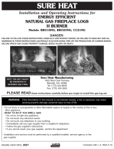
set will diminish the beauty of the hearth setting. Fig.
4-1 illustrates the critical dimensions of the fi rebox.
This gas log set must be installed by an NFI Certifi ed
or other qualifi ed professional installer. The Real-
Fyre
®
gas log set is to be installed only in a solid-fuel
burning fi replace with a working fl ue and constructed
of noncombustible material. The fi replace must have
an open damper. The chimney must be free of any
obstructions.
The fi replace must have a gas supply line that has
been installed by a qualifi ed technician in accordance
with all local codes. The gas supply line must have a
½" minimum interior diameter. If the gas line to the
replace is longer than 20', a larger diameter line may
be necessary.
Be sure to clean the fi replace oor of any ashes or other
foreign materials. It is recommended that the fi replace
and chimney be examined and cleaned by a chimney
sweep or other qualifi ed person before you install the
Real-Fyre
®
gas log set, and annually thereafter.
Required Gas Pressure: The minimum inlet gas-
supply pressure for the purpose of input adjustment
is 5" for natural gas and 10" for propane gas. The
maximum inlet gas-supply pressure for this burner is
10.5" for natural gas and 13" for propane gas.
Testing the Gas Supply System: The gas log set and
its individual shut-off valve must be disconnected from
the gas supply piping system while performing any
tests of the piping system at pressures in excess of ½
psig (3.5 kPa). The gas log set must be isolated from
the gas supply piping system by closing its individual
manual shut-off valve during any pressure testing of
the gas supply piping system at test pressures equal
to or less than ½ psig (3.5 kPa). This is accomplished
by closing the gas supply line valve, which is required
by NFPA 54, section 5.54.
Fig. 4-1
Fireplace dimensions
Important: For safe operation and proper performance of this product and to comply with certifi cation, listings,
and building code acceptances, use ONLY Peterson Real-Fyre
®
controls, parts, and accessories
that have been specifi cally listed or certifi ed for use with this burner system. Use of other controls,
parts, or accessories is prohibited and will void all warranties, certifi cations, listings, and building
code approvals, and may cause property damage, personal injury, and loss of life.
* This required width allows for centering of the log set.
Burner
size
Min. Fireplace Dimensions BTU
Width* Depth Height NAT.
16/19" 25" 15" 18" 45k
18/20" 26" 17" 18" 80k
24" 30" 17" 18" 90k
30" 36" 17" 18" 110k
36" 42" 22" 18" 130k
42" 48" 22" 18" 150k
48" 54" 22" 18" 170k
60" 66" 22" 18" 190k
Front
Rear
Opening
width
Depth
Front width
height
* For Masonry-Built Fireplaces; add 4 sq. in. to amount shown.
Minimum Free Opening Area of Chimney Damper for Venting (sq. in.)
For Factory-Built Fireplaces *
Chimney
Height
16/19" 18/20" 24" 30" 36" 42" 48" 60"
15' (min.)
29 50 57 57 82 94 107 119
20'
26 45 51 51 73 85 96 107
30'
23 41 46 46 66 76 86 96
5
L-A2-297
REV 0 -1407291445
INSTALLING THE DAMPER CLAMP
INSTALLATION
The damper clamp with hex bolt (Fig. 5-1) is provided as a means to prevent
full closure of the damper blade. The clamp is easily attached to most damper
blades with pliers or a wrench, and must be permanently installed. The clamp
is designed to prevent accidental closure of the damper when installed as
illustrated (
Fig. 5-2 and Fig. 5-3). Should the clamp not fi t, or fail to provide the
permanent vent opening listed in the table found above, have a permanent
stop installed, remove the damper blade, or have the
damper cut to provide the minimum permanent opening
required.
Note: These are minimum damper opening
specifi cations. The damper must be completely
opened when operating this gas appliance to
achieve the best ventilation possible.
Fig. 5-1
Damper clamp
Set screw
Fig. 5-2 Fig. 5-3
Open
Closed
Fig. 5-4
Gas supply
line stub
Gas line
cap
Fig. 5-5 Log locators on grate
INSTALLING THE BURNER
The Real-Fyre gas log set must be installed by a qualifi ed professional service technician. Instructions must be
followed carefully to ensure proper performance and full benefi t from the gas log set. This log set is designed
and labeled for natural gas. Check to be sure natural gas is supplied to the fi replace. Fireplace fl oor
must be level, clean, and smooth.
WARNING: Failure to position the parts in accordance with these diagrams or failure to use only parts
specifi cally approved with this appliance may result in property damage or personal injury.
REFER TO THE PARTS LIST WHEN FOLLOWING THESE INSTRUCTIONS.
The burner pan is supplied with a fuel injector for natural gas. The fuel injector must be used in ALL
installations. The fuel injector has a precisely sized orifi ce to ensure only the proper quantity of gas enters
the burner. This allows maximum performance and gas conservation.
1. MAKE SURE THE FIREPLACE GAS SUPPLY IS TURNED OFF.
2. Locate the gas-supply stub inside the fi replace and remove the cap, if attached (see Fig. 5-4).
CAUTION: When removing the cap, make sure the stub does not turn, loosening the connection inside the wall.
3. Locate the grate (Item 7) and attach the log locators (Item 13) to the 2 outer bars of the grate with screws
and nuts. The log locators should be positioned on the middle of the bars with screw slots facing towards
replace side walls (Fig. 5-5).
4. Attach the small adapter (Item 9C) to the fuel injector on the burner pan, using a pipe compound resistant
to all gases. Tighten securely. DO NOT REMOVE THE FUEL INJECTOR. Then attach one end of the fl ex
connector (Item 9B) to the small adapter. Tighten securely.
5. Place the burner pan into the fi replace so that it is centered.
6
L-A2-297
REV 0 -1407291445
INSTALLATION (cont.)
6. Be sure gas to the fi replace is off. Attach the large
adapter (Item 9A) to the gas-supply stub using a pipe
compound resistant to all gases. Tighten securely.
Then attach the open end of the fl ex connector to the
large adapter. Tighten securely. Ensure the pan rests
level on the fi replace oor after connection. Adjust the
pan if necessary.
7. LEAK TEST: Use a long-necked butane lighter, or
lay a lighted match next to the burner pipe, and
carefully turn on the gas supply until the burner
ignites. Test at all connections for leaks using the
appropriate soapy water solution. If bubbles appear,
a leak is present. Turn off the gas and tighten at all
connections. Repeat until no leaks are present. If a
leak persists, turn off the gas supply and contact the
local gas company or dealer. NEVER USE A FLAME
TO CHECK FOR LEAKS.
Turn off the gas supply prior to proceeding.
GRANULE, EMBER, AND GRATE PLACEMENT
GRANULE PLACEMENT
The sand granules supplied with the unit are specially selected
for use with natural gas. They maximize fl ame distribution and
reduce carbon buildup.
1. Fill the burner pan completely with the granules (Item 11).
See Fig. 6-2.
2. Slope the granules at the same angle as the burner pan.
This is important to ensure quiet lighting and even fl ame
distribution.
3. Pour a small amount of the granules along the outside edges
of the burner pan (Fig. 6-2). This prevents fl ame diversion.
EMBER PLACEMENT
Sprinkle the glowing embers (Item 10) lightly and evenly over the entire surface of the granules (in the pan
only). Break up any clumps that may have developed during shipment.
Important: Do not add any additional embers to this log set. Any additional embers may cause unsafe
operation.
GRATE PLACEMENT
Center the grate over the burner pan.
Fig. 6-1 - Fireplace valve
Fuel injector
Flex
connector
Large
Adapter
Burner pan
Gas
supply stub
Small
adapter
Fig. 6-2 Granule placement
Burner pan
Granules
7
L-A2-297
REV 0 -1407291445
LOG PLACEMENT
Fig. 7-1
CAUTION: Burn hazard. Logs will remain hot for some time after use. You must maintain the
log layout as shown to ensure proper operation of your log set. If you need to
reposition any log to maintain the proper layout, use heat-resistant gloves or allow
logs adequate time to cool before handling.
1. Log placement is very important for the proper
operation and performance of the Real-Fyre
®
gas
log set. Although you have some fl exibility in the log
arrangement, it is necessary to follow the log placement
instructions carefully to fully enjoy the log set.
2. Place the bottom logs on the grate. The log locators
ensure that adequate space between the logs is
maintained for a clean burn (Fig.
7-1).
3. Place the middle/top logs diagonally with space between
the logs so that the fl ames are not choked off. Adjust
the middle/top logs until desired look, and fl ame pattern
are achieved. Flexibility is possible provided excessive
sooting does not result from fl ames striking the logs too
directly. Reference Fig. 7-2 for some examples.
Styles and sizes will vary depending upon the log set
ordered. If the log set ordered includes placement
instructions; follow those instructions.
Fig. 7-2
8
L-A2-297
REV 0 -1407291445
LIGHTING THE GAS LOG SET
1. Lay a lighted long-stem match on the surface of the embers near the gas inlet (do not hold the match
in your hand) or use a lighted long-necked butane lighter.
2. Slowly turn the fi replace remote valve to the ON position. The log set should light.
3. If the log set does not light before the match goes out, immediately turn the valve off.
4. Wait approximately fi ve (5) minutes to clear out any gas, and repeat steps 1-3 above. Smell for gas
including near the fl oor. If you smell gas, stop and follow step B above. If you don’t smell gas, proceed.
5. If the log set fails to light again, turn off the valve and contact the dealer or gas supplier.
TURNING OFF THE GAS LOG SET
1. To extinguish; simply turn the valve to the OFF position. Be sure the valve is turned completely off to avoid
any gas leakage.
FOR YOUR SAFETY, READ BEFORE LIGHTING
WARNING: If you do not follow these instructions exactly, a fi re or explosion may result, causing property
damage, personal injury, or loss of life.
A. BEFORE LIGHTING, smell all around the gas
log set area for gas. Be sure to smell next to the
oor because some gas is heavier than air and
will settle on the fl oor.
B. IF YOU SMELL GAS:
Shut off the gas to the appliance.
Extinguish any open fl ame.
If odor continues, keep away from the
appliance, and immediately call the gas
supplier or fi re department.
C. Do not use the gas log set if any part has been
underwater. Immediately call a qualifi ed service
technician to inspect the gas log set and to replace
any part of the control system and any gas control
that has been underwater.
OPERATING THE LOG SET - LIGHTING AND EXTINGUISHING
9
L-A2-297
REV 0 -1407291445
MAINTENANCE
Once installed and operating properly, the Real-
Fyre
®
gas log set requires very little maintenance.
You should inspect the log set and control annually
for the following:
1. Excessive sooting - Some sooting of the log set
is normal and adds to the appearance of burned
wood. If sooting accumulates, you may brush the
soot off with a stiff brush. Do not use water or
soot cleaners to clean off the soot.
2. Settling of glowing embers and granules -
Moisture may cause the granules and glowing
embers in the burner pan to settle and affect
the burn. Using a screwdriver or fl at blade knife,
carefully stir the granules and embers, loosening
the materials.
3. Debris around the burner - Inspect the burner
pan to be sure it is free of any debris.
SERVICE
While some minor service conditions may
be handled by the owner of the log set, it is
recommended that a qualifi ed service technician be
called to service the gas log set and burner should
service be required. The TROUBLESHOOTING
section of these instructions serves as a guide for
ensuring optimum performance of the gas log set.
FLAME DESCRIPTION
Observe the fl ames. The main burner fl ames should
be blue at the base and a combination of blue/
yellow at the body and at the tips. They should be 5"
to 8" above the logs, with the center fl ame being the
tallest. Flames in the ember burner should be
1
/
4
"
above the embers.
TECHNICAL DATA AND SPECIFICATION INFORMATION
To adjust the fl ame pattern, take a long blade screwdriver or similar tool and stir the granules until the desired
pattern is achieved. DO NOT REMOVE GRANULES FROM THE BURNER PAN
10
L-A2-297
REV 0 -1407291445
TROUBLESHOOTING THE GAS LOG SET
SYMPTOM CAUSE SOLUTION
1. Excessive smoking
and sooting
Note: Like burning natural
rewood, the Real-
Fyre
®
gas log set
is designed to
burn with a yellow
smoky fl ame. Some
sooting is common
and desirable.
A. Poor draft or down draft A. Check for chimney blockage.
Be sure chimney is at least
3' taller than anything within
10’ of it in all directions. If
not, consult a chimney sweep.
Chimney cap or fan may help.
Under severe conditions, you
may need to open a window
near the fi replace about 1" to
2" when burning the log set.
C. Damper closed C. Open damper fully when
operating gas log set.
D. Set is positioned too close
to the front of the fi rebox
D. Move set so that the back of
the grate touches the back wall
of the fi rebox.
E. Improper log placement E. Be sure the bottom logs are
spaced at least 3" apart. Top
logs should be placed to
minimize fl ame impingement.
2. Low fl ame A. Incorrect log set size for
burner system
A. Consult the dealer for proper
set.
B. Insuffi cient gas supply B. Other gas appliances may
be competing for gas supply.
Consult installer or plumber.
Orifi ce size is based upon
7" w.c. pressure for natural
gas. Plumbing must supply
adequate pressure.
C. Blockage or kink in
connector kit, plumbing or
burner orifi ce
C. Clean out blockage. If
connector kit is kinked, replace
it.
D. Valve not fully open D. Open valve fully.
11
L-A2-297
REV 0 -1407291445
TROUBLESHOOTING THE GAS LOG SET (cont.)
SYMPTOM CAUSE SOLUTION
3. Uneven fl ame distribution
(Lower at one end of the
burner)
A. Clogged or blocked
portholes
A. Portholes can be cleared of
foreign object by running a
wire through them.
B. Insuffi cient gas pressure
and/or supply
B. Consult installer or plumber
(see solution 2b).
C. Granules may be packed
down too tightly or not
evenly
C. Loosen granules around
burner pipe by running a
kitchen knife along both
sides of pipe. Even out
granules in burner pan.
D. Auxiliary shut-off valve
partially closed
D. Open valve fully. Usually,
you will fi nd this along the
wall 3’ from the fi replace.
12
Robert H. Peterson Co. • 14724 East Proctor Avenue • City of Industry, CA 91746
A COPY OF YOUR SALES SLIP FOR PROOF OF PURCHASE IS REQUIRED
This warranty applies to the original purchaser for products which are installed in the United States or Canada and which are operated and maintained
as intended for single family residential usage. This warranty is valid only with proof of purchase, shall commence on the date of purchase, and shall
terminate (both as to original and any replacement products) on the anniversary date of the original purchase of the product stated on the above schedules.
This warranty covers defects in material and workmanship. This warranty does not cover parts which become defective as a result of negligence, misuse,
use not in compliance with the Owner’s Manual/Installation Instructions, accidental damage, improper handling, improper storage, improper installation,
lack of required routine maintenance (as specifi ed in the Owner’s Manual/Installation Instructions), electrical damage, local gas impurities or failure to
protect against combustibles. Product must be installed (and gas must be connected) as specifi ed in the Owner’s Manual/Installation Instructions by
a qualifi ed professional installer. Modifi cations to products which are not specifi cally authorized will void this warranty. Accessories, parts, valves,
remotes, etc. when used must be Peterson products or this warranty is void. Warrantied items will be repaired or replaced at Peterson’s sole discretion.
This warranty does not apply to rust, corrosion, oxidation, or discoloration unless the affected part becomes inoperable.
This warranty does not cover labor or labor related charges, except as provided by separate specifi c written programs from the Peterson Co. All repair
work must be performed by a qualifi ed professional service person and requires prior approval of Peterson.
Peterson may require the defective product or part to be returned to the factory to determine the cause of failure. Peterson will pay freight charges if
the product or part is determined to be defective. This warranty does not cover breakage in shipment from our (Independent) distributor to its customer
if the damage is determined to have occurred during that shipment.
This warranty specifi cally excludes liability for indirect, incidental, or consequential damages. Some states and provinces do not allow the exclusion
or limitation of incidental or consequential damages, so the above exclusion may not apply to you. This warranty gives you specifi ed legal rights, and
you may have other rights that vary from state to state or province.
For additional information regarding this warranty, or to place a warranty claim, contact the R. H. Peterson dealer where the product was purchased.
TO REGISTER YOUR PRODUCT ONLINE GO TO: WWW.RHPETERSON.COM,
AND CLICK ON PRODUCT REGISTRATION. THANK YOU FOR YOUR PURCHASE.
PETERSON VENTED DECORATIVE GAS APPLIANCE
LIMITED WARRANTY
Robert H. Peterson Co. ("RHP") warrants your Real Fyre
®
vented decorative gas appliance to be free from defects in material and
workmanship.
Peterson vented ceramic refractory gas logs are warranted for as long as you own them (lifetime).
Peterson vented burner assemblies are WARRANTED for TEN (10) YEARS. Peterson vented outdoor stainless-steel burner
assemblies are warranted for FIVE (5) YEARS.
Peterson glass, gems, nuggets, and fi ber-ceramic blend gas logs are warranted for FIVE (5) YEARS.
SPK-26 controls are warranted for THREE (3) YEARS.
APK-17 controls (including -17 valve) are warranted for TWO (2) YEARS.
All other Peterson valves, pilots, and controls are warranted for ONE (1) YEAR (excluding batteries).
WARRANTY
  • Page 1 1
  • Page 2 2
  • Page 3 3
  • Page 4 4
  • Page 5 5
  • Page 6 6
  • Page 7 7
  • Page 8 8
  • Page 9 9
  • Page 10 10
  • Page 11 11
  • Page 12 12

Real Fyre G45-2 Owner's manual

Category
Fireplaces
Type
Owner's manual
This manual is also suitable for

Real Fyre G45-2 SS Outdoor is a natural gas burner system designed for use in see-through solid-fuel burning fireplaces. It features an unregulated burner system, making it easy to adjust the flame height and intensity to create a realistic fire look. With a variety of sizes available, the Real Fyre G45-2 SS Outdoor can accommodate different fireplace dimensions, ranging from 25 to 66 inches in width. The burner system includes a damper clamp to prevent accidental closure of the damper, ensuring proper ventilation.

Ask a question and I''ll find the answer in the document

Finding information in a document is now easier with AI