Page is loading ...

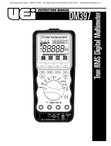
Model UT803
OPERATING MANUAL


TABLE OF CONTENTS
TITLE PAGE
3
4
5
6
8
9
10
11
12
16
16
18
20
22
24
26
28
30
32
33
33
33
34
34
35
35
Model UT803: OPERATING MANUAL
1
Overview
Unpacking Inspection
Safety Information
Rules For Safe Operation
International Electrical Symbols
The Meter Structure
Rotary Switch
Functional Buttons
Display Symbols
Measurement Operation
A. DC or AC Voltage Measurement
B. DC or AC Current Measurement
C. Measuring Resistance
D. Testing for Continuity
E. Testing Diodes
F. Capacitance Measurement
G. Frequency Measurement
H. Temperature Measurement
I . Measuring Transistor
Operation of Hold Mode
The POWER Button
The SELECT Button
Turning on the Display Backlight
The RANGE Button
The MAX MIN Button
AC/AC+DC Button

2
TITLE PAGE
35
36
36
37
38
38
39
41
42
43
44
44
45
46
47
47
48
48
49
51
52
52
53
53
54
54
55
55
55
Model UT803: OPERATING MANUAL
POWER INPUT Switch
Sleep Mode
RS232 Button
General Specifications
Accuracy Specifications
A. DC Voltage
B. AC Voltage
C. DC Current
D. AC Current
E. Resistance
F. Continuity Test
G. Diode Test
H. Capacitance
I . Frequency
J. Temperature
K. Transistor
Maintenance
A. General Service
B. Replacing the Fuses
C. Replacing the Battery
RS232C and USB Serial Port
System Requirements for Installing the UT803 Interface Program
RS232C Serial Port
A. Connecting between the Meter and computer
B. RS232C Port Cable
C. Setting of RS232C Serial Ports
USB Serial Port
A. Connecting between the Meter and computer
B. Setting of USB Serial Ports

3
Overview
This Operating Manual covers information on safety
and cautions. Please read the relevant information
carefully and observe all the Warnings and Notes strictly.
Warning
To avoid electric shock or personal injury, read the
“Safety Information” and “Rules for Safety Operation”
carefully before using the Meter.
Digital Bench-Type True RMS Multimeter Model UT803
(hereafter referred to as “the Meter”) has autorange
and manual range options with maximum reading 5999
and 3 5/6 digits which has a unique outlook design.
In addition to all the conventional features including
DC/AC voltage, current, resistance, diode, continuity
test, capacitance, temperature
0
C and
0
F, transistor,
max/min, there is a data hold, low battery display, sleep
mode, RS232C and USB standard serial port for easy
connection with computer to realize macro recording
and monitoring and capture of transient dynamic data,
displaying change of waveform during the measurement,
providing data and evidence to engineering technicians
for scientific research.
This is also a highly applied digital multimeter of good
performance with full overload protection and display
backlight function.
Model UT803: OPERATING MANUAL

4
Unpacking Inspection
Open the package case and take out the Meter. Check the following items carefully to see any missing or damaged
part:
Item Description Qty
In the event you find any missing or damage, please contact your dealer immediately.
Model UT803: OPERATING MANUAL
Operating Manual
Test Lead
Alligator Clip
Multi-Purpose Socket
Point Contact Temperature Probe (to be used under 230
0
C temperature measurement)
Power Cord (AC 250V)
RS232C Interface Cable
USB Interface Cable
Installation Guide & Computer Interface Software (CD-ROM)
1
2
3
4
5
6
7
8
9
1 piece
1 pair
1 pair
1 piece
1 piece
1 piece
1 piece
1 piece
1 piece

5
Safety Information
This Meter complies with the standards IEC61010: in
pollution degree 2, overvoltage category (CAT. I 1000V,
CAT.II 600V) and double insulation.
CAT III: Distribution level, fixed installation, with smaller
transient overvoltages than CAT. IV
CAT IV: Primary supply level, overhead lines, cable
systems etc.
Use the Meter only as specified in this operating manual,
otherwise the protection provided by the Meter may be
impaired.
In this manual, a Warning identifies conditions and
actions that pose hazards to the user, or may damage
the Meter or the equipment under test.
A Note identifies the information that user should pay
attention on.
International electrical symbols used on the Meter and
in this Operating Manual are explained on page 8.
Model UT803: OPERATING MANUAL

6
Rules For Safe Operation
Warning
To avoid possible electric shock or personal injury,
and to avoid possible damage to the Meter or to the
equipment under test, adhere to the following rules:
Before using the Meter inspect the case. Do not use
the Meter if it is damaged or the case (or part of the
case) is removed. Look for cracks or missing plastic.
Pay attention to the insulation around the connectors.
Inspect the test leads for damaged insulation or exposed
metal. Check the test leads for continuity. Replace
damaged test leads with identical model number or
electrical specifications before using the Meter.
Do not apply more than the rated voltage, as marked
on the Meter, between the terminals or between any
terminal and grounding.
The rotary switch should be placed in the right position
and no any changeover of range shall be made during
measurement is conducted to prevent damage of the
Meter.
When the Meter working at an effective voltage over
60V in DC or 30V rms in AC, special care should be
taken for there is danger of electric shock.
Use the proper terminals, function, and range for
your measurements.
If the value to be measured is unknown, use the
maximum measurement position and reduce the
range step by step until a satisfactory reading is
obtained.
Do not use or store the Meter in an environment of
high temperature, humidity, explosive, inflammable
and strong magnetic field. The performance of the
Meter may deteriorate after dampened.
When using the test leads, keep your fingers behind
the finger guards.
Disconnect circuit power and discharge all high-
voltage capacitors before testing resistance, continuity,
diodes, current, or capacitance.
Before measuring current, check the Meter’s fuses
and turn off power to the circuit before connecting
the Meter to the circuit.
Model UT803: OPERATING MANUAL
l
l
l
l
l
l
l
l
l
l
l

7
Replace the battery as soon as the battery indicator
appears. With a low battery, the Meter might
produce false readings that can lead to electric shock
and personal injury.
Remove test leads, temperature probe, RS232C
interface cable, USB interface cable and alligator clip
from the Meter and turn the Meter power off before
opening the Meter case.
When servicing the Meter, use only the same model
number or identical electrical specifications
replacement parts.
The internal circuit of the Meter shall not be altered
at will to avoid damage of the Meter and any accident.
Soft cloth and mild detergent should be used to clean
the surface of the Meter when servicing. No abrasive
and solvent should be used to prevent the surface
of the Meter from corrosion, damage and accident.
The Meter is suitable for indoor use.
Turn the Meter power off when it is not in use.
Take out the battery when not using for a long time
if using battery to power on the Meter.
When using battery to power on the Meter, constantly
check the battery as it may lead when it has been
using for some time, replace the battery as soon as
leaking appears. A leaking battery will damage the
Meter.
Model UT803: OPERATING MANUAL
l
l
l
l
l
l
l
l
l

8
Model UT803: OPERATING MANUAL
International Electrical Symbols
AC or DC
Grounding
Double Insulated
Warning. Refer to the Operating Manual
Deficiency of Built-In Battery
Continuity Test
Diode
Capacitance Test
Fuse
Conforms to Standards of European Union

9
The Meter Structure (see figure 1)
1. LCD Display 2. Rotary Switch
3. Input Terminals 4. Functional Buttons
Model UT803: OPERATING MANUAL
(Figure 1)

10
Rotary Switch
Below table indicated for information about the rotary switch positions:
AC and DC voltage measurement
:Continuity test.
:Diode test.
:Resistance measurement.
Capacitance test
:Frequency measurement.
:Temperature in Fahrenheit
Temperature in celsius
Transistor test
AC or DC current measurement range from 0.1uA to 5999uA.
AC or DC current measurement range from 0.01mA to 599.9mA.
AC or DC current measurement range from 0.01A to 10.00A.
V
mA
A
A
Model UT803: OPERATING MANUAL
Rotary Switch Position
Function
Hz
0
F
0
C
hFE
Hz
0
F

11
Functional Buttons
Below table indicated for information about the functional button operations.
Turn the power on and off.
Turn the display backlight on and off.
Switches between AC and DC measurement.
Switches between continuity and diode and resistance measurements
Switches between frequency and Fahrenheit temperature.
Press HOLD to enter and exit the Hold mode in any mode, the Meter beeps.
Press RANGE to switch between manual and auto ranging.
Turn on or off the serial port interface without changing the original setting.
Starts recording of maximum and minimum values. Steps the display through high (MAX) and low (MIN).
To select AC or AC+DC measurement.
Model UT803: OPERATING MANUAL
Button
POWER
LIGHT
SELECT
HOLD
RANGE
RS232C
MAX MIN
AC AC+DC
Operation Performed
l
l
l

12
HOLD
hFE MIN
MAX
RS232
AC+DC Trus RMS
Auto Range Manual
Trms
0
C umVA
DC munF
0
F
~mV
Mk Hz
12 10 1 11
5.6.7
14
2
16
13 3 4
8
9
15
Model UT803: OPERATING MANUAL
Display Symbols (see figure 2)
(Figure 2)

13
Symbol
Number
Model UT803: OPERATING MANUAL
True RMS
HOLD
AC
DC
AC+DC
OL
,K ,M
A, mA, µA
Meaning
Indicator for true rms value.
Data hold is active.
Sleep Mode feature is enabled.
Indicates negative reading.
Indicator for AC voltage or current.
Indicator for DC voltage or current
Indicator for AC+DC measurement
The input value is too large for the selected range.
:Ohm. The unit of resistance.
:kilohm. 1 x 10
3
or 1000 ohms.
:Megaohm.1x10
6
or 1,000,000 ohms.
A :Amperes (amps).The unit of current.
mA:Milliamp. 1 x 10
-3
or 0.001 amperes.
µA : Microamp. 1x 10
-6
or 0.000001 amperes.
1
2
3
4
5
6
7
8
9
K
M

14
Symbol
Number
Model UT803: OPERATING MANUAL
Meaning
V : Volts. The unit of voltage.
mV: Millivolt.1 x 10
-3
or 0.001 volts.
F : Farad.The unit of capacitance.
mF: Millifarad.1 x 10
-3
or 0.001 farads
µF : Microfarad.1x10
-6
or 0.000001 farads.
nF : Nanofarad.1 x 10
-9
or 0.000000001 farads.
Centigrade temperature
Temperature in Fahrenheit
Hz : Hertz. The unit of frequency in cycles/second.
kHz : Kilohertz. 1 x 10
3
or 1,000 hertz.
MHz: Megahertz. 1 x 10
6
or 1,000,000 hertz.
Unit of transistor.
Test of diode
The continuity buzzer is on.
9
10
11
V, mV
F, mF,
µF,nF
0
C,
0
F
Hz, kHz,
MHz
β

15
Symbol
Number
Model UT803: OPERATING MANUAL
AutoRange
Manual
Meaning
12
13
14
15
16
Indicator of Auto or manual range
Display of maximum or minimum value.
Data output is in progress.
The battery is low.
Warning: To avoid false readings, which could lead to possible electric shock or
personal injury, replace the battery as soon as the battery indicator appears.
Transistor test is on
MAX
RS232
MIN
hFE

16
Measurement Operation
A. DC or AC Voltage Measurement (See figure 3)
Warning
To avoid harms to you or damages to the Meter from
electric shock, please do not attempt to measure
voltages higher than 1000V although readings may
be obtained.
To measure DC/AC voltage, connect the Meter as
follows:
Model UT803: OPERATING MANUAL
1.
2.
3.
Insert the red test lead into the V terminal and the
black test lead into the COM terminal. If the measured
value is less than 600mV, insert the red test lead
into mV terminal instead and press RANGE button
to select manual range 600.0mV mode, the LCD
displays “MANUAL” and “mV”.
Set the rotary switch to V ; press SELECT button
to select DC or AC measurement mode.
Connect the test leads across with the object being
measured. The measured value shows on the display.
AC measurement displays True RMS value.
(Figure 3)

4. Press AC/AC+DC button to measure AC+DC voltage’s
true RMS.
Note
In each range, the Meter has an input impedance of
10M except 600mV range has 3000M . This
loading effect can cause measurement errors in high
impedance circuits. If the circuit impedance is less
than or equal to 10k , the error is negligible (0.1%
or less).
When DC/AC voltage measurement has been
completed, disconnect the connection between the
testing leads and the circuit under test, and remove
the testing leads away from the input terminals of
the Meter.
17
Model UT803: OPERATING MANUAL
l
l

B. DC or AC Current Measurement (See figure 4)
Warning
Before connect the Meter in serial with the tested
return circuit, close the return circuit’s current to avoid
the dangerous of sparking.
If the fuse burns out during measurement, the Meter
may be damaged or the operator himself may be hurt.
Use proper terminals, function, and range for the
measurement. When the testing leads are connected
to the current terminals, do not parallel them across
any circuit.
To measure current, do the following:
18
Model UT803: OPERATING MANUAL
1.
2.
3.
4.
Insert the red test lead into the µA mA terminal and
the black test lead into the COM terminal.
Set the rotary switch to an appropriate measurement
position in µA , mA or A , press SELECT button
to select AC or DC measurement mode.
Connect the test leads in serial with the object being
measured. The measured value shows on the display.
AC measurement displays True RMS value.
Press AC/AC+DC button to measure AC+DC
current’s true RMS
(Figure 4)
/