Page is loading ...

Rev: C 20230728LL Doc. #ZBM001214
Appearance may vary slightly
Patents: www.oneida-air.com/patents
OWNER’S MANUAL
Dust Cobra
Dust Collector
Industrial
14 Gallon
#XCKM011400


1oneida-air.com
Table of Contents
System Start-Up Information 2
System Specications 6
System Contents 8
System Dimensions 10
Assembly Instructions 11
Maintenance 23
Troubleshooting 25
Warranty Information 26
Recommended Accessories 27
Recommended Accessories 28
Notes 29

Oneida Air Systems, Inc.2
System Start-Up Information
WARNING
1. READ and understand ALL instructions and warning labels BEFORE using the dust collector.
2. REPLACE warning labels if they become obscured or removed.
3. ALWAYS follow all applicable federal, state, local, OSHA, NFPA, or authorities having jurisdiction codes and
regulations when installing and operating this dust collector.
4. ENSURE that all users of this dust collector are informed of all warnings and precautions, safe use, and
maintenance procedures.
5. FULL mental alertness is required. e machine is not intended for use by persons (including children) with
reduced physical, sensory or mental capabilities, or lack of experience and knowledge
6. DO NOT allow use by or near children.
7. DO NOT allow to be used as a toy.
8. NEVER leave the dust collector running while unattended.
9. TURN OFF and UNPLUG the dust collector BEFORE walking away, servicing, or cleaning. Allow the fan
blower motor to come to a COMPLETE STOP before walking away or performing any maintenance, service,
cleaning, or adjustments. is eliminates the risk of injury from unintended startup or contact with live
electrical components.
10. ENSURE that your dust collector is turned OFF and UNPLUGGED during installation. is eliminates the
risk of injury from unintended startup or contact with live electrical components.
11. COMPLETELY INSTALL ductwork/ex hose before operating collector.
a. Seal ductwork with silicone sealant or duct tape if leaks are found.
b. Have dust drum in place and sealed.
c. NEVER operate without lter and cowling in place. is machine has high speed rotating elements than
can cause severe injury.
12. ONLY use the dust collector for its intended purpose as described in this manual. DO NOT force it or
an attachment to do a job for which it was not designed. Consult this owner’s manual or reach out for
recommended accessories.
13. ENSURE enough air volume is at the suction point to capture all the particulate generated.
Before Purchasing or installing a dust collection system the process owners/operators
are cautioned to do so in accordance with prescribed Federal, State, Local, OSHA, NFPA,
and any other applicable codes or regulations relating to the type of dust(s) you are
collecting.
This manual contains specific precautionary statements relative to worker safety. Read
thoroughly and comply as directed. The most up to date safety information can be found
on our website: oneida-air.com/safety

oneida-air.com 3
System Start-Up Information (Continued)
14. NEVER make modications without prior approval from Oneida Air Systems. Modifying the dust collector
or using it dierently than intended will void the warranty and may result in malfunction or mechanical
failure that leads to serious personal injury or death!
15. DO NOT locate or operate the system in moist, wet, poorly lit, or cluttered environments. Operating in these
areas can create shock hazards, increase the risks of accidents and injury, and/or lower the operating lifespan
of the dust collector.
16. DO NOT install in classied hazardous atmospheres without an enclosure rated for the application. System
Location must account for wind, seismic zone, and other load conditions. Codes may regulate acceptable
locations for installing dust collectors. Consult with the appropriate authorities having jurisdiction to ensure
compliance with all national and local codes regarding dust collector installation. Equipment must be
anchored in a manner consistent with local code requirements. Anchors must be sucient to support dead,
live, seismic, and other anticipated loads. Consult a qualied engineer for nal selection of anchorage.
17. ENSURE exhaust air is properly vented. It should NOT be vented into a wall, a ceiling, or a concealed space
of a building. Personal injury, death, and/or property damage can result from material discharge during
venting. e risk of personal injury and/or property damage can be minimized or avoided by locating vented
equipment outside buildings and away from normally occupied areas. If exhaust air is vented outside, you
must provide make up / return air. Flue gases (carbon monoxide) can be drawn into the shop from furnaces,
water heaters, or other appliances
18. INSPECT and MAINTAIN REGULARLY. Keep the dust collector in proper working order. A machine that
isn’t properly maintained, not working as it should, has been dropped, damaged, le outdoors, or dropped in
water could malfunction leading to serious personal injury or death!
19. AVOID CORD DAMAGE. DO NOT pull or carry by cord. DO NOT use cord as handle. DO NOT unplug
by pulling on cord. To unplug, grab the plug, DO NOT close door on cord or pull cord around sharp edges or
corners. DO NOT run dust collector over cord. DO NOT handle cord/plug with wet hands. Keep cord away
from heated surfaces.
20. ALWAYS check for damaged parts. A part that is damaged should be carefully checked to determine that
it will operate properly and perform its intended function. Immediately repair or replace damaged or mis-
adjusted parts before operating machine.
21. DO NOT put any object in openings. DO NOT use with any opening blocked. (Except when pulsing - See
Maintenance Section for more information.)
22. ALWAYS wear a NIOSH approved respirator when emptying dust bins and during operation. Some dust
created by power sanding, sawing, grinding, drilling, and other construction activities contains chemicals
known to cause cancer, birth defects or other long-term respiratory damage
23. ALWAYS keep hair, loose clothing, ngers, and all parts of body AWAY from openings and moving parts.
24. ALWAYS wear ANSI-approved safety glasses or a face shield when operating or observing machinery and
when emptying dust bin.
25. ALWAYS wear hearing protection during extended periods of operation.

Oneida Air Systems, Inc.4
System Start-Up Information (Continued)
1. THIS UNIT IS NOT RATED FOR USE IN COMBUSTIBLE ENVIRONMENTS.
2. DO NOT operate the dust collector in areas where explosion risks are high. Areas of high risk include, but
are not limited to, areas near pilot lights, open ames, or other ignition sources.
3. ONLY operate dust collector in locations that include a re suppression system or have a re extinguisher
available nearby.
a. e ABC type (dry chemical) is generally a good choice for small wood shops.
b. Additional information on portable extinguishers can be found in NFPA 10 (Standard for Portable Fire
Extinguishers).
4. DO NOT allow accumulation of layers of ne dust on horizontal surfaces. Especially overhead lights,
electrical boxes and fuse panels which can ignite dust. Keep the oor around the system clean and free of
scrap material, oil, grease.
5. ENSURE all equipment and ductwork is electrically grounded.
6. DO NOT use PVC drain pipe.
7. ALWAYS consult an electrician or qualied service personnel about wiring practices and electrical codes
in your area. ONLY allow an electrician or qualied service personnel to do electrical installation or repair
work.
8. ALWAYS disconnect power before accessing or exposing electrical equipment. Improper wiring can cause
re, electrocution, injury, or death.
9. DO NOT use to pick up anything that is burning or smoking, such as cigarettes, matches, or hot ashes.
10. DO NOT use to pick up liquids, ammable liquids, or combustible liquids, such as gasoline, or use in areas
where they may be present.
11. DO NOT use excessively large wood waste bins. Wood dust mixtures are highly ammable and can be
explosive
FIRE HAZARDS
Process owners/operators retain all responsibility for the suitability of fire and explosion
hazard mitigation, suppression, and isolation strategies and to follow all applicable
federal, state, local, OSHA, NFPA, or authorities having jurisdiction codes and regulations
when installing and operating this dust collector.
Improper operation of a dust control system may contribute to conditions in the work
area or facility that could result in severe personal injury and product or property
damage.
Oneida Air Systems assumes no responsibility or liability for the suitability of any fire and/
or explosion mitigation strategy, or any items incorporated into a collector as part of an
owner/operators hazard mitigation strategy.

oneida-air.com 5
Customer Service Dept.
1-866-387-8822 • support@oneida-air.com
System Start-Up Information (Continued)
12. ALWAYS check your dust bin for smoldering materials before leaving the shop.
13. NEVER introduce sparks or sources of ignition into the dust collector. Sparks can be generated in several
ways:
a. High speed sanders, abrasive planers, saws, and edgers may strike foreign material and create a red-hot
metal fragment.
b. Knots in hardwood can create frictional sparks.
c. Trapped metal, when drawn into the dust collection system, can spark against ductwork.
d. Check wood stock for old nails and screws which can create red-hot metal fragments.
14. DO NOT overload woodworking equipment, especially sanders, as excessive frictional heat can
spontaneously ignite dust. Sanders can produce concentrations of dust well into the combustible range.
15. ALWAYS check that all dust collection equipment is properly selected and sized for the intended use.
Authorities with jurisdiction should be consulted before installing to verify local codes and installation
procedures. In the absence of such codes, install collector according to the National Electric Code, NFPA No.
70-latest edition and NFPA 91, NFPA664 Code (NFPA 654 if combustible dust is present).

6Oneida Air Systems
System Specications
OPERATION
Fan Rating (Free Fan) 245CFM
Fan Rating (with Cyclone & Filter) 245 CFM @ 23" WC - Maximum Flow Rate
202 CFM @ 34" WC - with 25’ of 2.5"diameter ex hose
Maximum Suction Rating 70" WC
MOTOR AND ELECTRICAL
Motor Type UL listed Industrial motor
Voltage 110V
Amperage 15.5A
Power Cord Length 20'
Power Plug Included Yes
Power Plug Type 110V: NEMA
Recommended Circuit Size 20A
Sound Emission With Standard Silencer & Filter: 73 dBA @ 10 ft
CARTRIDGE FILTER
Filter Type GORE Cleanstream® HEPA Filters
Filter Rating 99.97% ltration eciency at 0.3 microns (µm)
Pulse Type Manual Internal Rapid Pulse Filter Cleaner System
Pulse Interval ~30 Minutes or as needed based on the situation
SYSTEM DIMENSIONS AND CONSTRUCTION
Cyclone Body Industrial, Static Conductive Resin
Inlet Size 2.5" O.D. (2.25" I.D.)
Inlet Dimensions 2.3" ID
Drum Type Reinforced Steel Drum with Painted Exterior
Container Size 17 Gallons/35 gallons
Overall Height 17 Gallon: 53.5" / 35 Gallon: 59.25"
Drum Dolly Height Add 4-7/8"
Overall Weight 17 Gallon: 45 lbs // 35 Gallon: 55.8 lbs

7oneida-air.com
System Specications
WARNING
This motor can expose you to chemicals,
including carbon black, which is known to
the State of California to cause cancer.
For more information go to
www.P65Warnings.ca.gov
Keep the Certicate of Compliance on hand while doing lead remediation

8 Oneida Air Systems
System Contents
Please unpack the parts carefully and conrm you have received each item listed here.
* Some components are pre-installed at the factory and are listed here for your convenience.
ID Part number Part description Qty
ABXM001205 110V Cobra Motor Assembly 1
B SCX001205D Molded Cobra Cone Assembly 1
C FCH000004 GORE® CleanStream Pro HEPA Filter 1
D STX000005 Stand Body 1
E STX041419 Stand Legs 4
F SMD140400 Drum Assembly 1
F1* SDS140000 14 Gallon Molded Drum 1
F2* RHL000604 Drum Window 1
F3* AFS103258 10-32 5/8" Phillips Pan Head Screws 4
F4* AFT901032 10-32 Nylock Nuts 4
F5* RHC000012 3" Caster with 5/16"-18 x 3/4" Stems 5
G AHX001214 14 Galon Cobra Hardware Kit 1
G1 AFS156075 5/16-18 X 3/4" Carriage Bolt 16
G2 AFW180000 5/16" Flat Washer 16
G3 AFT900516 5/16" - 18 Nylock Nut 16
G4 RHC000012 3" Caster with 5/16"-18 x 3/4" Stems 4
G5 RGZ040014 Bin Gasket 4
G6 STX000006 Handle Gasket 1
G7 AFL990001 Drum Latches 2
G8 AFS501032 10-32 1/2" Phillips Pan Head Screws 4
G9 AFT901032 10-32 Nylock Nut 4
G10 AFB155180 5/16-18 x 2-1/2" Hex Head Bolt 6
G11 AFB250125 1/4"-20 x 1 1/4" Carriage Bolt 1
G12 AFW180516 5/16" Rubber Washer 1
G13 AFW025000 1/4" Flat Washer 1
G14 AFT000005 1/4" Whiz-Lock Nut 1
G15 AFT000006 1/4"-20 Thumb Nut 1
G16 RHS000000 Vacuum Hose Storage Strap 1
G17 RLH000516 5/16" Push-In Plug 3
G18 ASC000015 Silicone Tube 1
G19 VSC001205 Velcro Tie Straps 3
G20 AFL001205 Motor Assembly Draw Latches 2
G21 AFS632438 6-32 x 7/16" Phillips Pan Head Screw 4
G22 AFT900632 6-32 Nylock Nut 4
ID Part number Part description Qty
G23 RGM250000 Cobra Motor Gasket 2
G24 AFJ051602 5/16"-18 x 2" J Bolt 2
G25 AFT155175 5/16" Whiz-Lock Nut 2
G26 RHS000010A Filter Retainer Strap 1
G27 ABF000500 1/2" Nylon Elbow 1
G28 RLH000002 Nylon Washer 1
G29 RLH000003 Rubber O Ring 1
G30 AHX000018 Quick Disconnect Kit 1
G30A RLH000006 1/4" NPT Nylon Elbow 1
G30B RLH000005 3/8” Socket 1
G30C RLH000004 3/8" Male Plug 1
G30D RLH000002 Nylon Washer 1
G30E RLH000003 Rubber O Ring 1
G30F RLH000007 Nylon Nut 1
G31 AHX000033 Tubing Assembly 1
G31A VRV050500 1/2" ID Clear Vinyl Tubing 1/3'
G31B AWV000050 1/2" ID Switch Valve 1
G31C VRV050500 1/2" ID Clear Vinyl Tubing 7'
G32 RGZ190000 Cobra Gasket 1
G33 AFS015920 1/4"-20 X 3/4" Hex Head Bolt 8
G34 AFW025000 1/4" Flat Washer 16
G35 AFT000005 1/4" Whiz-Lock Nut 8
G36 RHS000050 Vacuum Hose Tether Strap 1
G37 RHS203016 Ladder Lock Slider 2
G38 ACB360000 Turn Key Hose Clamp 1
G39 AXD000006 1" Hook Tape .16'
G40 AXD000007 1" Loop Tape .16'
G41 RLH000023 23 mm Button Plug 1
H AXB999110B Dust Sentry Bin Level Indicator 1
I ASK000000 Accessory Shop Vac Kit 1
I1 VSHRFB250 2.50" x 25' Hose 1
I2 ASV000000 CleanShop Accesories 1
I3 DRL040212 4 to 2-1/2" Reducer 1
If you cannot find an item on the list, examine the packaging materials very carefully for nested items. Please
note that certain components have been pre-installed. There may be hardware leftover.

G36
H
I1
I2
I3
G37
9oneida-air.com
System Contents (Continued)
A
C
B
D
F
G25
G11
G24 G26
G12 G17
G14
Hose Storage Hardware
Filter Attachment Hardware
Motor Attachment Hardware
Vent Tube Quick Disconnect Pack
Mounting Hardware
G13
G15
G18
G16
G19
G38
G30A
G30E G30F
G30B G30C
G30D
G29G28
G20 G21 G22
G23
G39
G41
G40
G7 G8
G9
G6G5
× 16
G2
× 8
G33
G31
× 8
G35
× 16
G34
× 16
G3
E
G10
Drum Hardware
× 16
G1
G4
G32
G27

10 Oneida Air Systems
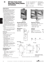
System Dimensions
Nominal dimensions shown. Dimensions subject to slight variations in manufacturing.
35-1/2"
901 mm
10-5/16"
262 mm
26-1/16"
661 mm
31-1/16"
788 mm
58-1/8"
1,476 mm
22-13/16"
579 mm

oneida-air.com 11
Assembly Instructions
1 Insert the Handle Gasket (G6) into the
Handle's opening (open, ribbed-side facing
upwards) and push it onto the Stand Body's
handle (D) so that it is fully covering the top
edge [FIG. 1a].
e Handle Gasket should be nested within
the divots on each side of the Handle [FIG.
1b]. Repeat for both Handles.
FIG. 1a
FIG. 1b
Divots
You will need the following tools:
GENERAL STAND
#2 Phillips Head Screwdriver 7/16" Wrench 1/2" Socket Wrench Channel Lock Pliers
3/8" Wrench 7/16" Socket Wrench Utility Knife Power Drill
5/16" Wrench 1/2" Wrench Drill Bit

Oneida Air Systems, Inc.12
Assembly Instructions (Continued)
FIG. 3a FIG. 3b
FIG. 3c FIG. 3d
FIG. 3e
G5
D
Threaded
Inserts
Threaded
Inserts
2 Insert four Hex Head Bolts (G10) down
through the threaded inserts on the Stand
Body (D) shown circled in [FIG. 2].
Note: ese will protrude down from the Stand
Body and help position the 14-gallon bin
directly underneath the cyclone.
FIG. 2
3 To Install the Bin Gasket (G5) onto the Stand
Body (D) using the previously installed Hex
Head Bolds (G10) as a guideline:
a. Turn the Stand Body (D) upside down
[FIG. 3a].
b. Lay out the four Bin Gasket segments
(G5). DO NOT REMOVE THE BACKER
TAPE [FIG. 3b].
c. Arrange the Bin Gasket segments (G5)
in a circle with the ends interlocking and
aligning to the rounded front edge of the
Stand Body [FIG. 3c].
d. Carefully mark a circle around the inside
of the arranged Bin Gasket segments (G5)
with a marker to create a reference line
[FIG. 3d].
e. Peel the backer tape o of the Bin Gasket
segments (G5) and adhere them to the
Stand Body (D), lining them up with your
reference line [FIG. 3e].
Note: We recommend removing the Lid Gasket's
backing paper as you go, rather than removing
it all at once. Press each gasket piece rmly onto
the Stand Body to ensure a long-lasting, airtight
seal.

oneida-air.com 13
Assembly Instructions (Continued)
4 Align each Stand Leg (E) to the Stand Body
(D) [FIG. 4a] and secure using four Carriage
Bolts (G1), four Washers (G2), and four
Nylock Nuts (G3) [FIG. 4b].
FIG. 4a
FIG. 4b

Oneida Air Systems, Inc.14
Assembly Instructions (Continued)
FIG.5
5 Align the Latches (G7) onto the holes on either
side of the Stand Body (D) and secure them
in place using two Pan-Head Screws (G8) and
Nylock Nuts (G9) [FIG 5].
Note: Firmly tighten this hardware. You may
need to open the latch to access the screw holes
for mounting. Allow for an additional 3" of
clearance around the system for ease of access to
the latches.
6 Secure Casters (G4) to the threaded insert
[FIG. 6a] on the bottom of each of the four
Stand Legs [FIG. 6b].
Note: For ease of assembly, we recommend
channel lock pliers to tighten the casters. Over
torquing can damage the connection point.
G9 G7 G8
FIG. 6a
FIG. 6b

15oneida-air.com
Assembly Instructions (Continued)
B
B
D
G32
G32
FIG. 9
G34
G34
G34
G33
FIG. 8
B
G16
G11 F11F10 F12 F13
FIG. 7bFIG. 7a
7 Choose one of the three holes on the Cone
Assembly (B) to store the Hose (I1) onto.
Turn Cone Assembly upside-down and install
one Carriage Bolt (G11), one Rubber Washer
(G12), two Flat Washers (G13), and a Whiz-
Lock Nut (G14) into the chosen hole as shown
in [FIG. 7a].
en attach Vacuum Hose Storage Strap (G16)
to the Carriage Bolt and secure in place with
the umb Nut (G15) [FIG. 7a].
Insert a Push-in Plug (G17) into the two
remaining holes [FIG. 7b].
Note: Silicone (G18) can be applied to the Push-
In Plugs for a more permanent installation.
8 Turn Cone Assembly (B) right side up and
align the Cobra Gasket (G32), the bottom
ange of the Cone Assembly (B), and the
Stand Body (D) [FIG. 8].
9 Secure the Cone Assembly (B) to the Stand
Body (D) with eight Hex Head Bolts (G33),
sixteen Flat Washers (G34), and eight Whiz-
Lock Nuts (G35) as shown in [FIG. 9].

Either Hole
16 Oneida Air Systems
Assembly Instructions (Continued)
10 Secure Nylon Elbow (G27) into upper drilled
hole with Rubber O Ring (G29), Nylon
Washer (G28), and the Nut included on the
Nylon Elbow (G27) [FIG. 10].
Refer to the Quick Disconnect Installation
Sheet (#ZBI000019) for more information.
11 Slide the shorter end of the Tube Assembly
(G31A) onto the Nylon Elbow (G27) as shown
in [FIG. 11a].
Note: If you are not using the automatic bag
holding feature of the system, the Switch Valve
(G31B) of the Tube Assembly MUST be in
the closed position. Otherwise leave the Tube
Assembly in the open position [FIG 11b].
FIG. 11b
B
G27G28G29G27
FIG. 11a
FIG. 10
Closed
Open
12 Take the Tubing Assembly (G31) and route it
through the closest retaining hole located in
the back corner of the Stand Body (D) [FIG.
12].
Note: Which hole you use will be determined
by the orientation of your Cone Assembly (B).
Use whichever hole is closest to ensure adequate
length for the Tubing Assembly (G31) to connect
to the Drum (F).
G31
D
G31
FIG. 12

oneida-air.com 17
Assembly Instructions (Continued)
Infrared
Sensor
Vinyl
Hose
Discharge
13 Install the Dust Sentry's (H) infrared sensor to
the pre-cut hole on the Stand Body (D). FIG.
13a].
• Refer to the Dust Sentry Instructions
#ZBI000002A
Note: If you are not using the Dust Sentry the
Button Plug (G41) MUST be installed in the
pre-cut hole on the Stand Body [FIG. 13b].
FIG. 13a
FIG. 13b
14 Install the Quick-Disconnect Kit (G30) onto
the pre-drilled hole near the bottom section of
the Drum (F) [FIG. 14a].
• Refer to the Quick Disconnect Installation
Sheet for more information.
Note: If you are not using the automatic bag
holding feature of the system, the Valve of
the Tube Assembly MUST be in the closed
position [FIG. 14b].
G30F
G30E
G30D
G30C
G30BG30A
FIG. 14a
FIG. 14b
Closed
Open

Oneida Air Systems, Inc.18
FIG. 15
Assembly Instructions (Continued)
G31C
FIG. 16
G30A
15 Center the Drum Assembly (F) underneath
the Stand Assembly and lower the Latches
(G7) so that they hook underneath the rim of
the Drum [FIG. 15]. e Latches can then be
closed to li the drum up from the ground and
seal the dust collector for operation.
Note: Be sure to rotate the Drum to ensure that
you can easily see the pre-installed ll viewing
window. e Hex Head Bolts (G10) installed
in Step 13 are guides for positioning the Drum
during latching. e back rim of the Drum
should be in light contact with both Hex Head
Bolts as the Drum is lied up and latched.
16 Attach the long end of the Tube Assembly
(G31C) onto the Nylon Elbow (G30A)
installed on the lower section of the Drum (F).
Push the Hose onto the tting so that all barbs
are covered [FIG. 16].
Note: If you are not using the automatic bag
holding feature of the system, the Valve of
the Tube Assembly MUST be in the closed
position.
/