Page is loading ...

CHANDELIER
Instruction Manual
Please read carefully and save these instructions, as you may need them at a later date.
SAFETY
WARNING: BE SURE THE ELECTRICITY TO THE WIRES YOU ARE WORKING ON IS SHUT OFF; EITHER THE FUSE
IS REMOVED OR THE CIRCUIT BREAKER IS TURNED OFF. TURNING THE POWER OFF USING THE LIGHT SWITCH
IS NOT SUFFICIENT TO PREVENT ELECTRICAL SHOCK.
NOTE: The important safeguards and instructions appearing in this manual are not meant to cover all possible conditions or
situations that may occur. It must be understood that common sense, caution, and care, are factors which cannot be built
into any product. These factors must be supplied by the person(s) installing this unit.
READ & SAVE THESE INSTRUCTIONS
CAUTION: Before assembling the lighting fixture, refer to the section titled Wiring Connections. If you feel you do not have
enough electrical wiring experience, either refer to a do-it–yourself wiring handbook or have your lighting fixture installed by
a qualified, licensed electrician.
UNPACK THE PACKAGE
Check the contents to be sure everything is included
Tools Needed: Slotted screwdriver, Adjustable wrench, Step ladder, Wire cutters, wiring supplies as required by electrical
code.
INSTALLATION & OPERATION INSTRUCTIONS
GENERAL
Before starting the installation, disconnect the power by turning off the circuit breaker or by removing the appropriate fuse at
the fuse box. Turning the power off using the light switch is not sufficient to prevent electrical shock.
All electrical connections must be in accordance with local and National Electrical Code (NEC) standards. If you are
unfamiliar with proper electrical wiring connections, obtain the services of a qualified electrician.
Remove the fixture and the mounting packages from the box and make sure that no parts are missing by referencing the
illustrations on the installation instructions.
Be sure to read these installation instructions and review the diagrams thoroughly before installation.
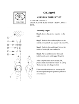
Assembly and Installation
1. Thread Iron Bar (20) into center column (21) until secure. Then adjust steel wire (19) length, Use Hex Wrench (18)
to thread Hex Screw (17) into Ball (16) tightly.
2. Thread Tube (24) onto threaded tube (22), then attach threaded tube (27) onto tube (24) and tighten until
secure. Place Cluster Assembly (25) through threaded tube (27) and then tighten with Hex Nut (26).
3. Place Cup (28) through threaded tube (27) and then tighten with Finial (29).
4. Make sure all the electrical is power off, and then attach the mounting plate (4) to the junction box (1) using the provided
machine screws (10).

5. Connect chain (14) with Canopy Loop (15) and hanging loop (12) together. Adjust the chain length as needed. Thread
Fixture wire (6) and ground wire (3) through the chain (14), ring (13), hanging loop (12), canopy (11) and threaded tube
(9).
6. Attach the ground wire (3) under the ground screw (5) marked “GND”, and fasten the ground screw (5) to the ground
wire (3) until secure. Connect black/smooth fixture wire to black supply wire and white/ribbed fixture wire to the white
supply wire using wire connectors (2) provided. Connect the fixture ground wire (3) and the house ground wire using
wire connectors (2) provided. Place wiring back in the junction box.
7. Place the Canopy (11) and ring (13) and onto the Junction box (1). Spin ring (13) onto hanging loop (12) until secure.
Note: According to your specific needs, you can adjust the length of threaded tube (9) by screwing it into the mounting plate
(4). And then Screw hex nut (7) to fasten it.
8. Screw bulb (10) into the socket (31).
ELECTRICAL CONNECTIONS
Required Supply Circuit: 120V, 60Hz
Connect the white wire(s) from the fixture to the white wire of the supply circuit. Connect the black wire(s) from the fixture to the black
wire of the supply circuit. Connect the green or bare copper wire to the ground wire of the supply circuit. Use UL/CSA listed wire
connectors suitable for the size type, and number of conductors. No loose strands or loose wires should be present. Secure wire
connectors with UL/CSA listed electrical tape.
1. Junction box
2. Wire connector
3. Ground wire
4. Mounting plate
5. Ground screw
6. Fixture Wire
7. Hex nut
8. Washer
9. Threaded tube
10. Machine Screw
11. Canopy
12. Hanging loop
13. Ring
14. Chain
15. Canopy Loop
16. Ball
17. Hex Screw
18. Hex Wrench
19. Steel Wire
20. Iron Bar
21. Center Column
22. Threaded tube
23. Glass Shade
24. Tube
25. Cluster Assembly
26. Hex. Nut
27. Threaded Tube
28. Cup
29. Finial
30. Bulb
31. Socket
/