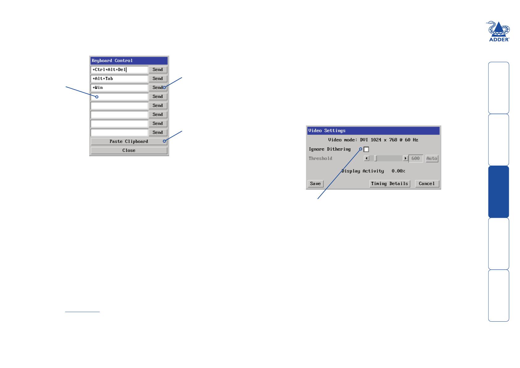
ADDER Digital ipeps Owner's manual

Category
KVM switches
Type
Owner's manual

This manual is also suitable for

AdderLink Digital iPEPS
User Guide

 




1
Contents - page 2
Contents
Introduction
AdderLink Digital iPEPS features ................................................4
What’s in the box ........................................................................5
What you may additionally need ...............................................5
Installation
Mounting .....................................................................................6
Connections .................................................................................7
Host computer ........................................................................7
IP network port ....................................................................... 8
Power supply connection .......................................................9
Configuration
Connecting to Digital iPEPS ......................................................10
Initial configuration ..................................................................11
Performing a flash upgrade ......................................................12
Flash upgrade using the remote method ...........................12
Flash upgrade using the dipswitch method .......................12
Operation
Using the viewer window ....................................................13
The menu bar ...................................................................13
When using the viewer window .....................................13
Host selection ........................................................................ 14
Configure .......................................................................... 14
Auto calibrate ........................................................................15
Re-synchronise mouse .....................................................15
Access mode - shared/private .............................................. 15
Power switching ....................................................................15
Editing the viewer window menu bar .................................16
Controls .................................................................................17
Single Mouse Mode .........................................................17
Resync Mouse ...................................................................17
Refresh Screen ..................................................................17
Mouse Control .................................................................. 17
Advanced mouse configuration ......................................18
Info .................................................................................... 18
Keyboard Control ............................................................. 19
Video settings ................................................................... 19
Sound control ...................................................................20
Virtual Media .......................................................................21
Remotely transferring files as a virtual disk drive ......... 21
Remotely exporting a disk drive to the host ..................22
Resetting the Digital iPEPS to factory default ....................23
 




2
HT
Further information
Getting assistance ......................................................................24
Appendix 1 - VNC viewer connection options .........................25
Display ...................................................................................25
Inputs ..................................................................................... 26
Connection ............................................................................27
Expert ....................................................................................27
Appendix 2 - VNC viewer window options ..............................28
Appendix 3 - Java viewer options .............................................29
Encoding and colour level .................................................... 29
Inputs ..................................................................................... 29
Security ..................................................................................29
Misc ........................................................................................ 29
Appendix 4 - Configuration menus ..........................................30
User accounts ........................................................................31
Gui edit configuration .....................................................32
Unit configuration ................................................................33
EDID configuration ..........................................................34
Advanced unit configuration ..........................................35
Time & date configuration ................................................... 37
Network configuration (IPV4) .............................................. 38
Network configuration (IPV6) .............................................. 39
Setting IP access control ...................................................40
Serial port configuration ...................................................... 41
Host configuration ................................................................42
Power switching configuration .......................................43
Logging and status ...............................................................44
LDAP configuration ..............................................................45
Appendix 5 - Networking issues ...............................................46
Positioning Digital iPEPS in the network ............................46
Placing Digital iPEPS behind a router or firewall ........... 46
Placing Digital iPEPS alongside the firewall ...................48
Appendix 6 - An introduction to IPv6 .....................................49
Vastly increased address space .............................................49
Standard subnet size ............................................................49
Address allocation ................................................................49
Mixing IPv4 and IPv6 ...........................................................50
Appendix 7 - The KVMADMIN utility .......................................51
Appendix 8 - Known working video modes ............................52
Appendix 9 - Product compatibility .........................................52
Appendix 10 – Hotkey sequences and Adder Port Direct .......53
End user licence agreement ......................................................55
Index
 




3
IP network/
Internet
PC
Introduction
Drawing upon our long and successful
history within the field of remote system
control, we have taken our best KVM via
IP technology and miniaturised it. The
result is the AdderLink Digital iPEPS, a
highly responsive, cost efficient way to
control a single system from any remote
position - worldwide.
Digital iPEPS stands for ‘Digital iP Engine
Per Server’ and gives an indication of the
clear design goals that have been applied
to this product since its conception. In
situations where a single system must be
placed in a relatively isolated location and
yet must be controlled from elsewhere,
then Digital iPEPS is the solution. The
host system can run its usual operating
system completely unchanged and needs
only to be connected to the compact
Digital iPEPS unit. This ensures that
there is no performance hit associated
with other remote solutions and also
provides the authorised remote user with
complete control. The remote user uses a
compact VNC viewer utility and can link
to the Digital iPEPS via any connected IP
network, or via the Internet.
IP network/Internet
The IP port allows direct connection
to an Ethernet-based local network
and from there onto the wider
Internet, as required.
Alternatively, the robust Digital iPEPS
security system will allow direct
connection to the outside world.
Four simultaneous remote users
Digital iPEPS can support four
remote users at any one time.
Adder Virtual Media feature
Allows an authorised remote user to
transfer files and folders to a host
computer, such that they appear as
though presented locally on removable
media (as would a memory stick or
CD-ROM). Via the IP network link, the
remote user can then control the host
and make use of the transferred files
and folders. An indispensable feature
when remotely upgrading or patching
distant host systems.
 




4
AdderLink Digital iPEPS features
The AdderLink Digital iPEPS unit uses the following connections to provide
secure remote access to a host computer.
1
ON
2
USB link for keyboard and mouse
Use this port to link the Digital iPEPS to
a USB port on the host computer. This
will provide USB keyboard and mouse
connections.
Video input
DVI/D digital video input from the
host computer.
Power input
Connect the supplied
power adapter here.
IP network port
This Ethernet port provides the connection
to the network. The port is intelligent
and can automatically sense whether it is
attached to a 10Mb or 100Mb network
and whether a cross-over or straight cable
is in use. The green and yellow indicators
provide useful status information.
Audio input
Optionally use the
supplied 3.5mm jack
cable to link this port
with the audio output
of the host computer.
USB link for the Adder Virtual Media feature
Optionally use this port to link the Digital iPEPS to
a USB port on the host computer. This will provide
a USB connection specifically for the Adder Virtual
Media feature.
RS232 serial input
Optionally use the
supplied power control
cable to link this port
with the RS232 port of
a power switch.
Configuration switches
SW1 is used to determine
how Digital iPEPS derives
its power. SW2 is used
to reset the Digital iPEPS
back to its factory defaults.
SW2 is also used during
firmware upgrades.
 




5
Whats in the box
Digital iPEPS module
What you may additionally need
CD-ROM
Power adapter plus country-
specific power cable
Part number: PSU-IEC-5VDC-2.5A
Four self-adhesive
rubber feet
3.5mm jack stereo audio cable
Part number: VSC22
2 x USB cable 2m (type A to B)
Part number: VSC24
Video cable 2m DVI/D to DVI/D
Part number: VSCD1
Rack chassis faceplate
Part number: X-RMK-FASCIA
Power control cable
Part number: VSC45
Rack mount chassis
Part number: X-RMK-CHASSIS
HDMI to DVI-D video cable
Part number: VSCD11
 




6
Installation
Mounting
The Digital iPEPS offers two main mounting
methods:
• Suppliedfourself-adhesiverubberfeet
• Rackchassisfaceplate-seebelow
Connections
Two countersunk screws are included to
attach the supplied faceplate to the Digital
iPEPs unit and one panhead screw is provided
to fix the faceplate to the rack chassis.
1
ON
2
HT
 




7
DVI-D video cable
USB cable for Adder Virtual
Media feature (optional
connection)
USB cable for
keyboard and
mouse links
Connections
Installation of the Digital iPEPS involves a number of basic
connections to some or all of the following items:
• Hostcomputer(below)
• IP network port
• Power supply
Host computer
The Digital iPEPS is connected to the host computer using the supplied DVI-D
video, USB, audio and power control cables (the latter two connections are
optional).
To attach the video and USB cables
1 Wherever possible, ensure that power is disconnected from the Digital iPEPS
and the computer. Live connections are possible but it is also preferable to
power down items before connection or disconnection.
2 Connect the supplied DVI-D cable to the video socket at one end of the Digital
iPEPS and connect the other end to the video output of the host computer.
3 Connect one of the supplied USB cables to the socket labelled and the
other end to a vacant USB port on the host computer.
4 [Optional step] If the Adder Virtual Media feature is required and/or you wish
to power the Digital iPEPS without using the supplied power adapter, then
also connect the other supplied USB cable to the socket labelled
If the VM USB connection is not
made then the supplied power
adapter must be used.
To attach the audio and power control cables
1 [Optional step] Where audio from the host computer is required, connect
the supplied 3.5mm jack stereo audio cable between the audio port of
the Digital iPEPS and the line output of the host computer.
2 [Optional step] Where a remote power switch is to be used with the host
computer, connect the supplied power control cable to the socket labelled
on the Digital iPEPS. Connect the other end to the serial port of the
remote power switch.
Power control cable for
use when a remote power
switch will be used
Audio connection to link
with the speaker output
of the host computer
 




8
IP network port
The Digital iPEPS provides an autosensing Ethernet IP port that can operate at 10
or 100Mbps, according to the network speed. The Digital iPEPS is designed to
reside easily at any part of your network:
• Itcanbeplacedwithinthelocalnetwork,behindanyrewall/router
connections to the Internet, or
• Itcanbeplacedexternallytothelocalnetwork,onaseparatesub-network
or with an open Internet connection.
Wherever in the network the Digital iPEPS is situated, you will need to determine
certain configuration issues such as address allocation and/or firewall adjustment
to allow correct operation. Please refer to Networking issues within the
Configuration chapter for more details.
IMPORTANT: When the Digital iPEPS is accessible from the public Internet, you
must ensure that sufficient security measures are employed.
To connect the IP network port
1 Depending upon where in the network the Digital iPEPS is being connected,
run a category 5e or 6 cable from the appropriate hub or router to the
Digital iPEPS.
2 Connect the plug of the category 5e or 6 cable into the IP port on the end
panel of the Digital iPEPS.
Category 5e or
6 link cable
3 Configure the network settings as appropriate to the position of the Digital
iPEPS within the network - see Networking issues for details.
 




9
Power supply connection
The Digital iPEPS provides flexibility in the way that it is powered in order to suit
your installation requirements. Each Digital iPEPS can be powered:
• ViabothUSB connections from the host computer, or
• Fromthesuppliedautosensingpoweradapter.
Power supply issues and options
If you intend to derive power from the host computer then both USB
connections must be made to the host computer. The Digital iPEPS will share its
requirements between the two ports and will automatically refuse to operate if
only one connection is made.
If you want to disable virtual media by omitting its USB cable, then you will need
to use the supplied power adapter. On the side panel of the Digital iPEPS, use
switch 1 to determine how power should be
derived:
SW1 OFF Derive Digital iPEPS power
from either the USB
connections or the supplied
power adapter.
ON Derive Digital iPEPS power
only from the supplied power
adapter.
To connect the power adapter
1 Connect the low voltage output connector from the power supply adapter
to the power socket on the end panel of the Digital iPEPS.
Low voltage
output connector
from the supplied
power adapter
1
ON
2
2 Connect the IEC connector of the supplied country-specific power lead to
the socket of the power supply.
3 Connect the power lead to a nearby mains supply socket.
Note: SW2 is used to reset the Digital iPEPS back to its factory defaults and is
also used during firmware upgrades.
 




10
Configuration
Connecting to Digital iPEPS
Connection to (and configuration of) Digital iPEPS is carried out over a network,
using a VNC Viewer program running on a computer or mobile device. VNC
Viewers are available for most computers, tablets and smartphones.
• IfyoualreadyhaveaVNCviewer,pleasefollowtheInitialconguration
instructions given on the next page.
If you do not already have a VNC viewer, there are three options:
• YoucandownloadaWindowsVNCViewerfromtheDigitaliPEPSitself.
• YoucandownloadthelatestVNCViewersformostoperatingsystemsvia
the RealVNC website, or for tablets and smartphones from the appropriate
app store.
• Withoutdownloadinganything,youcanrunaJavaversionoftheVNC
Viewer inside your web browser.
To download a Windows VNC Viewer from the Digital iPEPS unit
Note: The version of VNC supplied within the Digital iPEPS supports audio,
however, audio is not supported in the later viewers from RealVNC.
1 Connect the Digital iPEPS to an IP network where a suitable computer
is available on the same subnet (please see the Installation chapter for
connection details).
2 On that computer, open an internet browser and enter the default local IP
address used by the Digital iPEPS:
http://192.168.1.42
The Digital iPEPS welcome screen should be displayed:
3 Click the link Download the Windows VNC Viewer from unit.
4 Once the file is downloaded, run it and follow the on screen instructions
to open a VNC connection to the Digital iPEPS. (The VNC Viewer is a single
executable file which does not require an ‘installation’ step. Simply put the
file in a suitable place (such as the Desktop) and run it from there.)
To download a VNC Viewer
To download a (free) VNC Viewer for a desktop or notebook computer, visit the
download page of the RealVNC website:
http://www.realvnc.com/download/viewer
To download a VNC Viewer app for a tablet or smartphone, visit the Apple or
Android app store, or look at the RealVNC website (www.realvnc.com) for
further information.
To use the Java VNC Viewer
1 Connect the Digital iPEPS to an IP network where a suitable computer
is available on the same subnet (please see the Installation chapter for
connection details).
2 On that computer, open an internet browser and enter the default IP
address used by the Digital iPEPS:
http://192.168.1.42
The Digital iPEPS welcome screen should be displayed (as shown above).
3 ClickthelinkConnectusingbuilt-inJavaVNCViewer.TheJavaviewerwill
load and run inside the browser. For more details see Appendix 3 - Java
viewer options.
HT
 




11
Initial configuration
To perform the initial configuration, you need to connect the Digital iPEPS to an
IP network and use a computer located on the same network to connect to it.
To perform the initial configuration
1 Connect the Digital iPEPS to an IP network where a suitable computer is
available on the same subnet (please see the Installation chapter for
connection details).
2 Use a computer connected to the same subnet of the network.
On that computer, locate and select the VNC viewer icon
A connection details dialogue will be displayed:
4 Click the OK button. The viewer window may open straight away (if so
continue at step 6) or the system may require user authentication in which
case an authentication dialogue will be displayed:
Options button
Provides a range of viewer and connection settings - MORE [+]
Enter the Digital iPEPS
address here and click OK
If required, select the
encryption mode
5 Enter admin as the Username, leave the password entry blank and click
theOKbutton.Youwillnowbepromptedtoenteranewpasswordbefore
the Viewer window opens:
Click the Configure button
Use the various options
(particularly the ‘Unit
Configuration’ and ‘Network
Configuration’ options) to
arrange the Digital iPEPS to
suit your requirements.
See Appendix 4 -
Configuration menus.
6 Click the Configure button to display the Configuration menu:
3 In the ‘Server:’ entry, type the address: 192.168.1.42
 




12
Performing a flash upgrade
The firmware in Digital iPEPS is fully upgradable and there are two methods that
you can use:
•Theremotemethod,or
•The‘dipswitch’method.
The most streamlined upgrade procedure is the remote method because it is
carried out completely from a remote system. The ‘dip switch’ method is useful
because it can be carried out even if the firmware within the Digital iPEPS unit
has been corrupted.
Flash upgrade using the remote method
Using this method, the Digital iPEPS is upgraded via remote connection (through
the IP network port). Upgrades are digitally signed by Adder using a secure key.
This prevents unauthorised or altered firmware images being downloaded into
the unit.
To perform a flash upgrade
1 Download the latest firmware revision for the Digital iPEPS from the Adder
website and decompress the download file. View the decompressed files
and make a note of the name and location of the .bin file that was part of
the download file collection.
2 Make a remote connection to the Digital iPEPS unit and login as the admin
user.
3 Once logged in, click the ‘Configure’ button in the top right corner of the
window.
4 Click the ‘Unit Configuration’ button.
5 Click the ‘Advanced Unit Configuration’ button.
6 Click the ‘Upgrade Firmware’ button. A dialogue box will be displayed:
7 Note the IP address shown in the dialogue box and click OK.
8 The unit is now ready to accept the upgrade files. Open your browser and
log into the Digital iPEPS using the IP address that was confirmed in the
dialog. Once connected, the unit will offer the following screen:
9 Click the ‘Browse’ button and locate the .bin upgrade file that you
downloaded earlier. Click the ‘Perform Upgrade’ button. The upgrade will
take place and its progress will be shown on screen.
10 When the upgrade is complete, click the link ‘Click here to reboot the unit
into normal operation’.
Flash upgrade using the dipswitch method
Use the dipswitch method if the firmware on the Digital iPEPS has become
corruptedandthereisnoaccessfromaVNCsession.Youwillneedtoknowthe
IP address of the Digital iPEPS (the default IP is 192.168.1.42).
1 With the power off, change dip switch 2 to ON.
2 Power On the Digital iPEPS.
3UsingawebbrowsergototheIPaddressoftheDigitaliPEPS.Youshould
see the upgrade page as shown above.
4 Browse to the .bin file and then click the Perform upgrade button.
 




13
Operation
Using the viewer window
Once connected to the Digital iPEPS via the VNC Viewer (please see Connecting
to Digital iPEPS for details), the viewer window gives you the ability to view
and control the Digital iPEPS and its host computer(s). Its operation is almost
identicalregardlessofwhetheryouusedtheVNCvieweroryourJavaviewerto
display it.
The menu bar
The viewer window presents a menu bar similar to that shown below. Certain
items within the toolbar are displayed depending upon your access permissions
and/or the Digital iPEPS configuration.
When using the viewer window
What is the best screen resolution to use?
The best resolution for your computer is one that is larger than the screen of the host
computer that you are viewing. This will allow you to see everything without scrolling
around. Alternatively, the VNC viewer can be set to scale the image to fit your screen,
but remember that some pixel dithering effect will be seen when scaling is used.
How do I navigate around a larger screen?
If the screen that you are viewing has a larger resolution than your viewing
window you will need to scroll around to see all items. The viewer window
allows you to ‘bump scroll’ (only in full screen mode). This means that when
your mouse cursor bumps against the edge of the screen, the screen image will
scroll across automatically.
How do I escape from full screen mode?
Press the F8 button. This button is changeable but is most often set to F8.
How do I make the most of a slow connection?
The VNC viewer is slightly better suited to slower connections than the browser
viewer because it offers more options. Click the Options button of the VNC
viewer when entering the Digital iPEPS address during log on.
Rate limit mouse events
When selected, this mode greatly reduces the mouse movement data that are
sent to the host computer. When you move the local mouse, the remote cursor
will catch up roughly once per second.
For details about how to determine the options on the
menu bar, see Editing the viewer window menu bar.
Re-sync mouse
Ensures that the
mouse pointer
which you move
and the mouse
pointer on the
host system
are correctly
synchronised.
Controls
Displays a menu
of options
concerning
keyboard, video
and mouse
operation.
Access mode
Allows you
to choose
between
Shared and
Private access
modes.
Dialogue area
Indicates your username
and the host system that
you are currently viewing.
This area can also display
other messages.
Configure
This option is only
available to the
admin user and
provides access
to the main
configuration
menus.
Viewer options
(VNC viewer
only) Click the
VNC icon to
view the viewer
window options.
Power
Click to access
the power on/
off options for
the current
host computer.
Hosts
Click to
display a list
of computers.
Choose an
entry to
connect to
that host
computer.
Ctrl Alt Del
Sends the
Ctrl Alt Del
sequence
to the
current host
computer.
Auto calibrate
This button will
calibrate the
mouse, but only
when relative
mouse mode is
selected.
Note: During initial use, neither
the Hosts nor the Power buttons
will be present.
HT
 




14
Host selection
The Hosts button on the menu bar provides the quickest and most efficient way
to switch between host computers. This is because the button is close at hand,
but also because the screen calibration details for each host are reused when
this method of switching is used.
Note: The Hosts button is displayed only when the switching details for two or
more computers have been declared within the configuration section by the
admin user.
To select a host
1 Click the Hosts button to display a list of
computers.
2 Click the required computer name to view and
control it.
See Host configuration for details about
programming new hosts into the Digital iPEPS (‘admin’
user status required).
Configure
This option is displayed only when you are logged on as the ‘admin’ user. When
selected it provides access to a wide range of Digital iPEPS settings.
See Appendix 4 for more details.
 




15
Access mode - shared/private
Up to four users can be simultaneously logged-in and all will view the same
host. If you need to perform a sensitive task that should not be viewed by other
users, you can change the access mode to Private. This action prevents other
users connecting at the same time.
To change the access mode
1 Click one of the arrow buttons adjacent to the
Shared/Private indicator.
Power switching
When configured (and where you have access rights) this option allows you to
control the mains power input to the currently selected host computer.
Note: This option is generally used to power cycle remote systems that have
failed to respond. Before switching a system off, ensure that all attempts have
first been made to power it down through normal means.
To switch a system on or off
1 Use the Hosts button to select the required
computer.
2 Click the Power button and then select the Switch
on or Switch off option, as appropriate.
Auto calibrate
Auto calibrate will calibrate the mouse only if relative mouse mode is selected.
This detects the mouse motion and will report back that the mouse has been
calibrated correctly depending upon the operating system.
See the notes on Advanced mouse configuration for more details.
Once this has been done, providing you use the ‘Hosts’ button to switch
between host computers, the video settings for each machine will be re-used.
Re-synchronise mouse
If you find that your local mouse pointer and that of the host are not correctly
synchronised, use this feature to re-align their movements. This operation is also
selectable from the Controls menu.
To re-synchronise the mouse
1 Use the Hosts button to select the required computer.
2 Click the button and then click OK in the subsequent pop-up message.
Note: If you find that this doesn’t work, you may need to perform a mouse
calibration again.
 




16
Editing the viewer window menu bar
If required, you can customise the menu bar of the viewer window to ensure
that it contains only the necessary options.
The menu bar can be edited locally by each user or edited singly by the admin or
alternatively, the admin can globally alter the menu bar for all users.
To edit the menu bar locally
1 Login remotely via VNC viewer and display the viewer window.
2 Place the mouse pointer on the menu bar and click the right mouse button.
A popup will be displayed:
To edit the menu bar via admin
1 Login remotely via VNC viewer as admin user and display the viewer window.
2 Click the Configure button in the top right corner of the viewer window.
3 Click the User Accounts button.
4 Against the entry for the required user, click the Menu Bar Edit button. The
following dialogue will be displayed:
3 Click on any option within the popup to add it to or remove it from the
menu bar.
4 When all changes have been made, click anywhere else within the viewer
window.
Changes made in this way will affect the individual user only.
5 Select/deselect the items that you wish to appear on the menu bar. As you
do so, the Menu bar appearance image will show how the bar will look
using your edited settings.
6 Optional: To globally apply your changes, tick the Apply to all users on Save
option.
7 Click the Save button.
Note: The local menu bar edit popup shown above
will only appear if the Enable direct right click
Menu editing option is ticked within the Gui Edit
Configuration screen (for that user) as shown right.
 




17
Mouse Control
This option displays a mouse control dialogue and is useful when the remote
cursor is failing to respond correctly to your mouse movements, even after using
the Resync mouse option.
The mouse control dialogue allows you to control the remote mouse cursor
using a selection of buttons that you click with your local mouse.
Controls
When clicked, this button reveals a menu of
options concerned with keyboard, video and
mouse operation.
Single Mouse Mode
This mode is for fast network connections where
the cursor response is sufficient to provide instant
visual feedback on the remote screen. When
enabled, the cursor is ‘captured’ within the viewer
window until you use the ‘escape’ hot keys.
To quit from single mouse mode, press F8 and then P. Alternatively, enable and
use the mouse button escape sequences - see Advanced unit configuration
for details.
The single mouse mode does not require calibration.
Resync Mouse
This option has the same effect as the button on the menu bar and re-
synchronises the local and remote mouse pointers.
Refresh Screen
This option refreshes the whole screen image to remove any artefacts from
moved screen items. This is useful when using very low refresh rates on slow
speed communication links.
Click to move the remote
mouse cursor up, down,
left or right
Click to calibrate the
remote mouse
Click to produce a single
mouse click for the left,
centre or right mouse
buttons
Click to produce a
continuous mouse click
and hold for the left,
centre or right mouse
buttons
When ticked the unit
will attempt to switch
to Absolute Mouse
mode (recommended). If
the computer does not
support this then it will
display a warning and
return to relative mouse
mode.
Click to display
the Advanced
Mouse
Configuration
dialogue. See next
page.
 




18
Info
When selected, this option displays an information dialogue showing the current
logged on users, the current host, its video mode and its mouse motion details.
Advanced mouse configuration
This dialogue allows the mouse acceleration to be configured according to
the operating system in use and also permits manual fine tuning for situations
where problems are encountered with the Calibrate function.
For best results, choose the appropriate Change motion: entry to match the host
in use.
The available Change Motion schemes are: Constant, XFree86, Windows Pre-XP,
Windows XP, Windows XP SP2, OS/2, Solaris, Solaris 9 and Mac OSX. Most of
these offer the Speed setting as the only option, however, the Windows Pre-Xp
and XFree86 options contain many other parameters.
When the Absolute Mode option is ticked in the main Mouse Control menu,
this dialogue allows you to adjust the Absolute Offset scale:
 




19
Keyboard Control
This option displays a keyboard control dialogue and is useful for sending
keyboard combinations (to the host) that are needed regularly or that are
trapped by the Digital iPEPS.
When entering codes:
+ means press down the key that follows
means release the key that follows
+– means press down and release the key that follows
* means wait 250ms (note: if a number immediately follows the asterisk, then
the delay will equal the number, in milliseconds)
It is automatically assumed that all keys specified will be released at the end, so
there is need to specify -Ctrl or -Alt if these keys are to be released together.
Examples:
‘Ctrl + Alt 12’ would be expressed as: +Ctrl+ Alt+1–1+2
+N means press the ‘N’ key
+Scroll means press the Scroll lock key
+Space means press the space key
Click to send
the code
Enter the
code here
Click to send the
contents of the
clipboard to the host
Click to send
the code
Click to send the
contents of the
clipboard to the host
Ignore Dithering
The ‘Ignore Dithering’ option increases performance and reduces network
traffic when the host computer is an Apple Mac or another computer that
has dithered video output. It also improves performance if the video source is
noisy (e.g. from a camera or a VGA-to-DVI converter).
Video settings
This option provides a range of options related to the video configuration.
Dithering is a technique used by some graphics cards to improve perceived
image quality by continuously slightly varying the colour of each pixel. This gives
the illusion of more shades of colour than the display can really reproduce, and
smooths the appearance of gradually shaded areas in images. Unfortunately,
dithering is an issue for KVM extenders such as Digital iPEPS because it makes
the image appear to be changing all the time even when it is static. This means
that a great deal of unnecessary network data is sent to the VNC viewer,
reducing the video frame rate and making mouse response appear slow.
The Ignore Dithering option works by ignoring small variations in the video
from frame to frame. It is disabled by default to give full colour accuracy and the
best possible frame rate from non-dithered video sources.
The Threshold setting adjusts the level of dithering noise that is ignored. The
‘Auto’ button attempts to choose a suitable value automatically, but the level
can also be adjusted manually using the slider or arrow buttons. The best value
is of course a compromise between capturing all the ‘real’ screen changes whilst
ignoring the (almost invisible) dithering noise. A good way to choose the value
is to watch the Display Activity indicator for a static screen. If the Threshold
is too low, the Display Activity will be a high percentage while nothing is really
changing. If the Threshold is too high, the Display Activity will be very low (or
zero) but some real changes in the screen may be missed.
Note: If using the Paste Clipboard feature, within the VNC viewer properties,
ensure that in the Inputs section, the Share clipboard with server option is
enabled. See Appendix 1 for details.
  • Page 1 1
  • Page 2 2
  • Page 3 3
  • Page 4 4
  • Page 5 5
  • Page 6 6
  • Page 7 7
  • Page 8 8
  • Page 9 9
  • Page 10 10
  • Page 11 11
  • Page 12 12
  • Page 13 13
  • Page 14 14
  • Page 15 15
  • Page 16 16
  • Page 17 17
  • Page 18 18
  • Page 19 19
  • Page 20 20
  • Page 21 21
  • Page 22 22
  • Page 23 23
  • Page 24 24
  • Page 25 25
  • Page 26 26
  • Page 27 27
  • Page 28 28
  • Page 29 29
  • Page 30 30
  • Page 31 31
  • Page 32 32
  • Page 33 33
  • Page 34 34
  • Page 35 35
  • Page 36 36
  • Page 37 37
  • Page 38 38
  • Page 39 39
  • Page 40 40
  • Page 41 41
  • Page 42 42
  • Page 43 43
  • Page 44 44
  • Page 45 45
  • Page 46 46
  • Page 47 47
  • Page 48 48
  • Page 49 49
  • Page 50 50
  • Page 51 51
  • Page 52 52
  • Page 53 53
  • Page 54 54
  • Page 55 55
  • Page 56 56
  • Page 57 57
  • Page 58 58
  • Page 59 59

ADDER Digital ipeps Owner's manual

Category
KVM switches
Type
Owner's manual
This manual is also suitable for

Ask a question and I''ll find the answer in the document

Finding information in a document is now easier with AI