Page is loading ...

H3C S9500 Series Routing Switches
Installation Manual
Hangzhou H3C Technologies Co., Ltd.
http://www.h3c.com
Manual Version: T2-08048H-20071025-C-2.03
Product Version: S9500-CMW520-R2127

Copyright © 2006-2007, Hangzhou H3C Technologies Co., Ltd. and its licensors
All Rights Reserved
No part of this manual may be reproduced or transmitted in any form or by any means
without prior written consent of Hangzhou H3C Technologies Co., Ltd.
Trademarks
H3C, , Aolynk, , H
3
Care,
, TOP G, , IRF, NetPilot,
Neocean, NeoVTL, SecPro, SecPoint, SecEngine, SecPath, Comware, Secware,
Storware, NQA, VVG, V
2
G, V
n
G, PSPT, XGbus, N-Bus, TiGem, InnoVision and
HUASAN are trademarks of Hangzhou H3C Technologies Co., Ltd.
All other trademarks that may be mentioned in this manual are the property of their
respective owners.
Notice
The information in this document is subject to change without notice. Every effort has
been made in the preparation of this document to ensure accuracy of the contents, but
all statements, information, and recommendations in this document do not constitute
the warranty of any kind, express or implied.
To obtain the latest information, please access:
http://www. h3c.com
Technical Support
customer_service@h3c.com
http://www. h3c.com

About This Manual
Related Documentation
The related manuals are listed in the following table.
Manual Description
H3C S9500 Series Routing
Switches Operation Manual
It provides an operation guide. It consists of access
volume, IP service volume, IP routing volume, IP
multicast volume, MPLS/VPN volume, QoS/ACL
volume, security volume, system volume, and
acronyms.
H3C S9500 Series Routing
Switches Command Manual
It explains all commands available in the S9500
series and provides a list of commands the S9500
series do not support. It consists of the same
modules as the operation manual.
Organization
H3C S9500 Series Routing Switches Installation Manual is organized as follows:
Chapter Contents
1 Product Overview
Introduces the appearance, architecture and system
features of the S9500 series.
2 Preparing for Installation
Lists the preparations and precautions for the
installation.
3 Installing the Switch
Details the installation of the chassis, PSUs, boards
and cable connection for the S9500 series.
4 Commissioning the
Switch
Concentrates on the initial power-on and booting of
the S9500 series.
5 Troubleshooting and
Maintaining the Switch
Presents troubleshooting the switch ,the hardware
and software upgrade.
6 Appendix A Cable
Management
Introduces how to bind cables.
7 Appendix B Engineering
Labels for Cables
Introduces the use of engineering labels.

Chapter Contents
8 Appendix C Installation
of Lightning Arrester for
AC Power
Introduces the installation of lightning arrester for AC
power of S9500 series routing switches.
Conventions
The manual uses the following conventions:
I. Command conventions
Convention Description
Boldface
The keywords of a command line are in Boldface.
italic
Command arguments are in italic.
[ ]
Items (keywords or arguments) in square brackets [ ] are
optional.
{ x | y | ... }
Alternative items are grouped in braces and separated by
vertical bars. One is selected.
[ x | y | ... ]
Optional alternative items are grouped in square brackets
and separated by vertical bars. One or none is selected.
{ x | y | ... } *
Alternative items are grouped in braces and separated by
vertical bars. A minimum of one or a maximum of all can be
selected.
[ x | y | ... ] *
Optional alternative items are grouped in square brackets
and separated by vertical bars. Many or none can be
selected.
&<1-n>
The argument(s) before the ampersand (&) sign can be
entered 1 to n times.
# A line starting with the # sign is comments.
II. GUI conventions
Convention Description
< >
Button names are inside angle brackets. For example, click
<OK>.
[ ]
Window names, menu items, data table and field names
are inside square brackets. For example, pop up the [New
User] window.
/
Multi-level menus are separated by forward slashes. For
example, [File/Create/Folder].

III. Symbols
Convention Description
Warning
Means reader be extremely careful. Improper operation
may cause bodily injury.
Caution
Means reader be careful. Improper operation may cause
data loss or damage to equipment.
Note Means a complementary description.
Environmental Protection
This product has been designed to comply with the requirements on environmental
protection. For the proper storage, use and disposal of this product, national laws and
regulations must be observed.

Installation Manual
H3C S9500 Series Routing Switches Table of Contents
i
Table of Contents
Chapter 1 Product Overview ........................................................................................................1-1
1.1 Introduction........................................................................................................................1-1
1.2 Physical Structure..............................................................................................................1-1
1.2.1 Chassis and Slots ...................................................................................................1-2
1.2.2 Backplane................................................................................................................1-5
1.2.3 Power System.........................................................................................................1-6
1.2.4 PoE Power Supply..................................................................................................1-8
1.2.5 Fan Tray................................................................................................................1-10
1.3 Switching and Routing Processing Unit...........................................................................1-11
1.4 Line Processing Unit........................................................................................................1-12
1.5 Service Board ..................................................................................................................1-14
1.6 System Specifications......................................................................................................1-14

Installation Manual
H3C S9500 Series Routing Switches Chapter 1 Product Overview
1-1
Chapter 1 Product Overview
1.1 Introduction
The S9500 Series Routing Switches (hereinafter referred to as the S9500 series) are
developed by Hangzhou H3C Technologies Co., Ltd. (hereinafter referred to as H3C)
for use on business-oriented enterprise networks, the distribution layer of large MANs,
the core layer of small MANs, and the backbone of large enterprise networks and
campus networks. They can serve as switching cores and convergence centers.
Currently, the S9500 series consist of the following models:
z S9505: This model provides a switching capacity of up to 600 Gbps. It allows for
the concurrent wire-speed forwarding on 240 GE ports, 20 × 10GE ports, 240 FE
electrical ports, or 100 FE optical ports.
z S9508: This model provides a switching capacity of up to 960 Gbps. It allows for
the concurrent wire-speed forwarding on 384 GE ports, 32 × 10GE ports, 384 FE
electrical ports, or 160 FE optical ports.
z S9508V: This model provides a switching capacity of up to 960 Gbps. It allow for
the concurrent wire-speed forwarding on 384 GE ports, 32 × 10GE ports, 384 FE
electrical ports, or 160 FE optical ports. This model adopts upright slots.
z S9512: This model provides a switching capacity of up to 1.44 Tbps. It allows for
the concurrent wire-speed forwarding on 576 GE ports, 48 × 10GE ports, 576 FE
electrical ports, or 240 FE optical ports.
Note:
Unless otherwise specified in this document, the S9508V and the S9508 have the
same configuration.
1.2 Physical Structure
The S9500 series use integrated chassis, which consists of a power area, board area,
backplane, and fan area.

Installation Manual
H3C S9500 Series Routing Switches Chapter 1 Product Overview
1-2
Note:
z Two switching and routing processor units (SRPUs) can be installed on the S9500
series to support active-standby switchover.
z Two power supply units (PSUs) can be installed on the S9500 series to provide
hot-standby 1+1 redundancy.
z The S9500 series support PoE and an external PoE power supply is optional.
z Boards, fan tray, and AC/DC PSUs are hot-swappable.
1.2.1 Chassis and Slots
I. S9505
(1) SRPU slots (2) LPU slots (3) Cable management bracket
(4) PSUs (5) PoE power entry module (6) Fan tray
Figure 1-1 Front view of the S9505
z The S9505 chassis provides seven slots in its board area: The top two
accommodate SRPUs, which can operate in 1+1 redundancy mode; the remaining
five accommodate LPUs/service boards.
z At the bottom of the chassis is the power area that contains one PoE entry module
and two PSUs. The two PSUs are hot-swappable; they can operate in 1+1
redundancy mode. The switch supports both AC and DC power inputs. So you can
select AC or DC PSUs as needed.

Installation Manual
H3C S9500 Series Routing Switches Chapter 1 Product Overview
1-3
z On the right of the chassis is the fan area that contains one vertical fan tray. The
fans draw air in from the left and exhausts air from the right.
II. S9508
(1) LPU slots (2) SRPU slots (3) PSUs
(4) PoE power entry module (5) Fan tray
Figure 1-2 Front view of the S9508
z The S9508 chassis provides ten slots in its board area: The middle two
accommodate SRPU modules; the remaining eight accommodate LPUs/service
boards.
z At the bottom of the chassis is the power area that contains one PoE power entry
module and two PSUs. The switch supports both AC and DC power inputs. So you
can select AC or DC PSUs as needed.
z On the right of the chassis is the fan area that contains one vertical fan tray. The
fans draw air in from the left and exhausts air from the right.

Installation Manual
H3C S9500 Series Routing Switches Chapter 1 Product Overview
1-4
III. S9508V
(1) Fan tray (2) LPU slots (3) SRPU slots
(4) Air filter (5) PSUs (6) PoE power entry module
Figure 1-3 Front view of the S9508V
z The S9508V chassis provides ten vertical slots in its board area: The middle two
accommodate SRPU modules; the remaining eight accommodate LPU/service
boards.
z At the bottom of the chassis is the power area that contains one PoE power entry
module and two PSUs. The switch supports both AC and DC power inputs. So you
can select AC or DC PSUs as needed.
z Above the power area is the air filter, which can be removed from the chassis in
the case of replacement or regular cleaning.
z On the top of the chassis is the fan area that contains one horizontal fan tray. The
fans draw air in from the bottom and exhaust air from the top.

Installation Manual
H3C S9500 Series Routing Switches Chapter 1 Product Overview
1-5
IV. S9512
(1) LPU slots (2) SRPU slots (3) PSUs
(4) PoE power entry module (5) Fan trays
Figure 1-4 Front view of the S9512
z The S9512 chassis provides fourteen slots in its board area: The middle two
accommodate SRPU modules and the remaining twelve accommodate
LPUs/service boards.
z At the bottom of the chassis is the power area that contains one PoE entry module
and two PSUs. The switch supports both AC and DC power inputs. So you can
select AC or DC PSUs as needed.
z On the right of the chassis is the fan area that contains two vertical fan trays. The
fans draw air in from the left and exhaust air from the right.
1.2.2 Backplane
The backplane of the S9500 series allows high-speed data exchange between SRPUs
and LPUs, as well as the exchange of various management and control signals in the
system.

Installation Manual
H3C S9500 Series Routing Switches Chapter 1 Product Overview
1-6
I. Functions
The following are the main functions of the backplane:
z Providing communication channels for signal exchange between boards
z Supporting board hot-swapping
z Supporting board auto-discovery in slots
z Connecting PSUs to distribute power SRPUs, LPUs/service boards, and fan tray(s)
and providing monitor channels for them.
II. Structure
The S9500 series use a passive backplane, which provides multiple board slots, one or
two fan interfaces, and two –48V power interfaces (one for PSUs and the other for PoE
power entry module).
1.2.3 Power System
Note:
z The S9500 series support both AC and DC power inputs. So you can choose AC or
DC PSUs as needed.
z The S9500 series support 1+1 power supply redundancy.
z The PSUs of the S9500 series are hot-swappable.
The power system is at the bottom of the chassis. In the PSU slots, you can insert either
two AC PSUs or two DC PSUs. The PSUs are cooled by the built-in fans, which draw
air into the chassis from the front and exhaust air from the rear.
z AC PSU
Table 1-1 Specifications for AC PSUs
Specifications
Item
NEPS1200-A NEPS2000-A NEPS3500-A
Model S9505 S9508/S9512 S9508/S9512
Rated
voltage
range
100 to 240 VAC, 50
Hz or 60 Hz
100 to 120 VAC, 60 Hz
200 to 240 VAC, 50 Hz
100 to 240 VAC,
50 Hz or 60 Hz
Input
voltage
range
90 to 264 VAC, 50 Hz
or 60 Hz
90 to 264 VAC, 50 Hz or
60 Hz
90 to 264 VAC, 50
Hz or 60 Hz

Installation Manual
H3C S9500 Series Routing Switches Chapter 1 Product Overview
1-7
Specifications
Item
NEPS1200-A NEPS2000-A NEPS3500-A
Max
input
current
15 A 15 A
Single 1800 W
sub-PSU :15 A
Two 1800W
sub-PSUs: 30 A
Table 1-2 Configuration and output power of AC PSUs
PSU Configuration
Maximum output
power
NEPS1200-A
1 × NEPS1200-A, no redundancy
2 × NEPS1200-A, 1+1 redundancy
1200 W (90 V to 264 V)
NEPS2000-A
1 × NEPS2000-A, no redundancy
2 × NEPS2000-A, 1+1 redundancy
1200 W (90 V to 160 V)
2000 W (160 V to 264 V)
1 × NEPS3500-A enclosure + 1 ×
sub-PSU, no redundancy
1 × NEPS3500-A enclosure + 2 ×
sub-PSU, 1+1 redundancy
1200 W (90 V to 180 V)
1800 W (180 V to 264 V)
1 × NEPS3500-A enclosure + 2 ×
sub-PSU, no redundancy
2 × NEPS3500-A enclosure + 3 ×
sub-PSU, 2+1 redundancy
2 × NEPS3500-A enclosure + 4 ×
sub-PSU, 2+2 redundancy backup
2400 W (90 V to 180 V)
3500 W (180 V to 264 V)
NEPS3500-A
2 × NEPS3500-A enclosure + 3 ×
sub-PSU, no redundancy
2 × NEPS3500-A enclosure + 4 ×
sub-PSU, 3+1 redundancy
3500 W (90 V to 180 V)
z DC PSU
Table 1-3 Specifications for DC PSUs
Specifications
Item
NEPS1200-D NEPS2000-D NEPS3500-D
Model S9505 S9508/S9512 S9508/S9512
Rated
voltage
range
–48 to –60 VDC –48 to –60 VDC –48 to –60 VDC
Input
voltage
range
–36 to –72 VDC –36 to –72 VDC –36 to –72 VDC

Installation Manual
H3C S9500 Series Routing Switches Chapter 1 Product Overview
1-8
Specifications
Item
NEPS1200-D NEPS2000-D NEPS3500-D
Max
input
current
25 A 42 A 75 A
Max
output
power
1,200 W 2,000 W 3,500 W
1.2.4 PoE Power Supply
The S9500 series support power over Ethernet (PoE). With this feature, an S9500
switch equipped with an external PoE power supply and PoE-capable LPUs can deliver
–48 VDC to its remotely powered devices (PDs), such as IP phones, wireless LAN
(WLAN) access points (APs) and network cameras, through Ethernet cables.
Currently, among the LPUs of the S9500 series, only GV48 is PoE capable.
z The S9500 series can supply power to remote PDs through Ethernet electrical
ports on the LPUs. Each LPU can simultaneously supply power to up to 48 PDs
with the maximum distance of 100 m (328.1 feet).
z Each Ethernet port can deliver up to 15.4 W to its PD.
z The S9500 series determine whether to deliver power to a newly detected PD
according to the following condition: If the remaining PoE power of the switch is
greater than what is required by a newly detected PD, the switch supplies power to
it. Otherwise, the switch does not supply power to it.
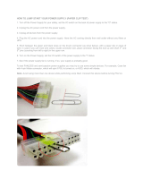
I. PoE power entry module
The PoE-supported S9505/S9508/S9508V/S9512 switch chassis has a PoE power
entry module between the two PSUs. You can connect this PoE power entry module to
an external PoE power supply PSE4500-A.
Figure 1-5 PoE power entry module

Installation Manual
H3C S9500 Series Routing Switches Chapter 1 Product Overview
1-9
II. External PoE power supply
The S9505/S9508/S9508V/S9512 uses the PSE4500-A power system as an external
PoE power supply.
Figure 1-6 shows the PSE4500-A front panel.
Figure 1-6 PSE4500-A front panel
Table 1-4 describes typical equipment configurations and specifications of PSE4500-A.
Table 1-4 Typical equipment configurations and specifications of PSE4500-A
Item Specifications
Physical dimensions (H × W × D)
175 × 482.6 × 320.5 mm (6.89 × 19.00 × 12.62
in.)
System controller One
Rectifiers (NP2500UAC)
Two NP2500UACs (required) + one redundant
NP2500UAC (optional); NP2500UAC is
hot-swappable
AC accessories
Three AC inputs and switches
Three AC voltage detection circuits
Input voltage range: 90 to 264 VAC
DC accessories
A single DC output, with a max output power of
4500 W (220 V)/2400 W (110 V)
The external PoE power system has the monitoring function. It provides one RS232
and two RS485 monitoring interfaces. The external PoE power supply can display
alarm information through the ALM LED. The system can learn the running information
of the rectifiers by connecting a monitoring port to the SRPU. You can use cables to
connect the monitoring ports from the front or the rear of the external PoE power
supply.

Installation Manual
H3C S9500 Series Routing Switches Chapter 1 Product Overview
1-10
Note:
The external PoE power system for the S9500 series only support RS485 monitoring
ports.
Table 1-5 LEDs of external PoE power system
LED Label Color
Normal
state
Abnormal
state
Abnormal reason
Input power
LED
AC Green ON OFF
Loss of AC input
power, or blown fuse
Output
power LED
DC Green ON OFF
No DC output from
PSU
Fault LED Fault Red OFF ON
Irreversible fault
occurred in PSU
Running
status LED
RUN Green ON OFF
PSU shutdown or
PSU running trouble
Alarm LED ALM Red OFF ON
Loss of AC input
power, under-voltage
or over-voltage input,
over-voltage output,
output short-circuit,
or PSU fault
1.2.5 Fan Tray
z The S9505 uses one 25 W fan tray, which contains four 120 × 120 × 25.4 mm (4.7
× 4.7 × 1.0 in.) DC fan units.
z The S9508 uses one 35 W fan tray, which contains six 120 × 120 × 25.4 mm (4.7 ×
4.7 × 1.0 in.) DC fan units.
z The S9508V uses one 70 W fan tray, which contains six 120 × 120 × 38 mm (4.7 ×
4.7 × 1.5 in.) DC fan units.
z The S9512 uses two 25 W fan trays, each of which contains four 120 × 120 × 25.4
mm (4.7 × 4.7 × 1.0 in.) DC fan units.
The fans of the S9505/S9508/S9508V/S9512 operate at –48 VDC supplied from the
backplane.

Installation Manual
H3C S9500 Series Routing Switches Chapter 1 Product Overview
1-11
Figure 1-7 Fan tray panel of the S9505/S9508/S9512
Figure 1-8 Fan tray panel of the S9508V
Table 1-6 LEDs on fan tray panel
LED Color Status Meaning
OFF The fan tray is faulty.
RUN Green
ON The fan tray is operating normally.
OFF The fan tray is operating normally.
ALM Red
ON The fan tray is faulty.
1.3 Switching and Routing Processing Unit
SRPUs serve as the core of the S9500 series. They mainly have the following
functions:
z Route calculation and forwarding table maintenance.
z Integrating crossbar switching fabric to accomplish service exchange between
different boards.
z Providing system configuration and monitoring functions, which allows the system
to monitor other boards and upgrade/reset service board software.
The following table lists the SRPUs applicable to the S9500 series.

Installation Manual
H3C S9500 Series Routing Switches Chapter 1 Product Overview
1-12
Table 1-7 SRPUs applicable to the S9500 series
SRPU S9505 S9508 S9508V S9512
LSB1SRP1N4
9
LSB1SRP1N5
9
9
LSB1SRP1N6
9
LSB1SRP1N7
9
9
9
9
LSB1SRP2N4
9
LSB1SRP2N5
9
9
LSB1SRP2N6
9
LSB1SRP2N7
9
9
9
9
LSB2SRP2N4
9
LSB2SRP2N5
9
9
LSB2SRP2N6
9
LSB2SRP2N7
9
9
9
9
Note:
The tick 9 indicates that the SRPU is applicable to the switch. SRP2N’s forwarding
capacity is twice the SRP1N’s.
1.4 Line Processing Unit
The following LPUs are available:
Table 1-8 LPUs available
LPU Suffix User interface
LSB1FP20 B0, CA0 20 × 100 Mbps SFP/LC optical ports
LSB1F32G B0, CA0
4 × 1000 Mbps SFP/LC optical ports and 32 ×
auto-sensing 10/100 Mbps RJ-45 ports
LSB1FT48 B0 48 × auto-sensing 10/100 Mbps RJ-45 electrical ports
LSB2FT48 CA0 48 × auto-sensing 10/100 Mbps electrical ports
LSB1GP12
B0, CA0,
DB0
12 × 1000 Mbps SFP/LC optical ports
LSB1GP24
B0, CA0,
CB0, DB0,
DC0
24 × 1000 Mbps SFP/LC optical ports

Installation Manual
H3C S9500 Series Routing Switches Chapter 1 Product Overview
1-13
LPU Suffix User interface
LSB2GP24 DB0, DC0 24 × 1000 Mbps SFP/LC optical ports
LSB1GP48 DB0
48 × 1000 Mbps SFP/LC optical ports (1:4
convergence)
LSB1GP48L DB0 48 × 1000 Mbps SFP/LC optical ports (wire-speed)
LSB1GV48 DB0
48 × auto-sensing 10/100/1000 Mbps RJ-45
electrical ports (PoE-capable)
LSB2GV48 DB0
48 × auto-sensing 10/100/1000 Mbps RJ-45
electrical ports (PoE-capable)
LSB1GT24
B0, CA0,
DB0
24 × auto-sensing 10/100/1000 Mbps RJ-45
electrical ports
LSB2GT24 DB0
24 × auto-sensing 10/100/1000 Mbps RJ-45
electrical ports
LSB1GT48L DB0
48 × auto-sensing 10/100/1000 Mbps RJ-45
electrical ports (wire-speed)
LSB1P4G8 CA0
8 × 1000 Mbps SFP/LC optical ports and 4 × OC-3c
SFP/LC POS optical ports
LSB1GT8P CA0
4 × 1000 Mbps SFP/LC optical ports and 8 ×
auto-sensing 10/100/1000 Mbps RJ-45 ports
LSB1XP2
B0, CA0,
CB0, DB0,
DC0
2 × 10GBase-R XFP/LC/10GBase-W XFP/LC optical
ports
LSB1XP4
B0, CA0,
DB0
4 × 10GBase-R XFP/LC/10GBase-W XFP/LC optical
ports (1:2 convergence)
LSB1XP4L DB0
4 × 10GBase-R XFP/LC/10GBase-W XFP/LC optical
ports (wire-speed)
LSB1XP4T DB0
4 × 10GBase-R XFP/LC/10GBase-W XFP/LC optical
ports
LSB1XK1
B0, CA0,
DB0
1 × 10GBase-R XENPAK/SC port
LSB1SP4 CA0 4 × OC-48c SFP/LC POS optical ports
LSB1UP1 CA0 1 × OC-192c XFP/LC POS optical port
LSB1VP2 CA0 2 × OC-192c XFP/LC RPR optical ports
LSB1RSP2 CA0 2 × OC-48c SFP/LC RPR optical ports

Installation Manual
H3C S9500 Series Routing Switches Chapter 1 Product Overview
1-14
Note:
The first column and the second column in the above table form an LPU model, for
example, LSB1XP2B0.
1.5 Service Board
Each kind of service board is specially designed for high-speed processing of a certain
service and has partial or no functions of LPU.
Currently, the following service boards are available:
z LSB1NATB0: for NAT service, no service port
z LSB1VPNB0: for VPLS service, no service port
z LSB1NAMB0: for NAM service, no service port
Note:
For detailed specifications for the SRPUs, LPUs, and service boards, visit the website
at www. h3c.com.
1.6 System Specifications
The following table summarizes the physical specifications of the S9500 series.
Table 1-9 Technical specifications of the S9500 series
Item S9505 S9508 S9508V S9512
Dimensions
(H × W × D)
486 × 436 ×
450 mm (19.1
× 17.2 × 17.7
in.)
619 × 436 × 450
mm (24.4 × 17.2
× 17.7 in.)
888 × 436 ×
450 mm (35 ×
17.2 × 17.7
in.)
753 × 436 × 450
mm (29.6 × 17.2
× 17.7 in.)
Weight (full
load)
≤ 65 kg (143
lb)
≤ 80 kg (176 lb)
≤ 90 kg
(198.4 lb)
≤ 100 kg (220
lb)
Max power
consumption
1,200 W 2,000 W 2,000 W
2,000 W/3,500
W
Overall
switching
capacity
SRP1N6:
300 Gbps
SRP2N6: 600
Gbps
SRP1N5:
480 Gbps
SRP2N5:
960 Gbps
SRP1N5:
480 Gbps
SRP2N5:
960 Gbps
SRP1N4:
720 Gbps
SRP2N4:
1.44 Tbps
Number of
VLANs
4 K
/