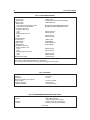
Yamaha DragStar XVS1100 Owner's manual
- Category
- Toy vehicles
- Type
- Owner's manual
This manual is also suitable for

WARNINGS, CAUTIONS
AND NOTES
The terms WARNING, CAUTION and NOTE
have specific meanings in this manual.
A WARNING emphasizes areas where injury or
even death could result from negligence. Mechani
-
cal damage may also occur. WARNINGS should be
taken seriously.
A CAUTION emphasizes areas where equipment
damage could result. Disregarding a CAUTION
could cause permanent mechanical damage, though
injury is unlikely.
A NOTE provides additional information to
make a step or procedure easier or clearer. Disre
-
garding a NOTE could cause inconvenience but
would not cause equipment damage or personal
injury.
SAFETY
Professional mechanics can work for years and
never sustain a serious injury or mishap. Follow
these guidelines and practice common sense to
safely service the motorcycle.
1. Do not operate the vehicle in an enclosed area.
The exhaust gasses contain carbon monoxide, a poi-
sonous gas that is odorless, colorless, and tasteless.
Carbon monoxide levels build quickly in a small
enclosed area, and it can cause unconsciousness and
death in a short time. Make sure the work area is
properly ventilated or operate the vehicle outside.
2. Never use gasoline or any extremely flammable
liquid to clean parts. Refer to Cleaning Parts and
Handling Gasoline Safely in this section.
3. Never smoke or use a torch in the vicinity of
flammable liquids, such as gasoline or cleaning sol
-
vent.
4. When welding or brazing on the motorcycle, re
-
move the fuel tank, carburetor and shocks to a safe
distance at least 50 ft. (15 m) away.
5. Use the correct type and size tool to avoid dam
-
aging fasteners.
6. Keep tools clean and in good condition. Replace
or repair worn or damaged equipment.
7. When loosening a tight fastener, be guided by
what would happen if the tool slips.
8. When replacing fasteners, make sure the new
fasteners are of the same size and strength as the
original ones.
9. Keep the work area clean and organized.
10. Wear eye protection any time the safety of your
eyes is in question. This includes procedures in
-
volving drilling, grinding, hammering, compressed
air and chemicals.
11. Wear the correct clothing for the job. Tie up or
cover long hair so it cannot be caught in moving
equipment.
12. Do not carry sharp tools in clothing pockets.
13. Always have an approved fire extinguisher
available. Make sure it is rated for gasoline (Class
B) and electrical (Class C) fires.
14. Do not use compressed air to clean clothes, the
motorcycle or the work area. Debris may be blown
into your eyes or skin. Never direct compressed air
at yourself or someone else. Do not allow children
to use or play with any compressed air equipment.
15. When using compressed air to dry rotating
parts, hold the part so it can not rotate. Do not allow
the force of the air to spin the part. The air jet is ca-
pable of rotating parts at extreme speed. The part
may be damaged or disintegrate, causing serious
injury.
16. Do not inhale the dust created by brake pad and
clutch wear. In most cases, these particles contain
asbestos. In addition, some types of insulating ma-
terials and gaskets may contain asbestos. Inhaling
asbestos particles is hazardous to health.
17. Never work on the vehicle while someone is
working under it.
18. When placing the vehicle on a stand, make sure
it is secure before walking away.
Handling Gasoline Safely
Gasoline is a volatile, flammable liquid and is one
of the most dangerous items in the shop.
Because gasoline is used so often, many people
forget that it is hazardous. Only use gasoline as fuel
for gasoline internal combustion engines. When
working on a vehicle, remember that gasoline is al
-
ways present in the fuel tank, fuel lines and carbure
-
tors. To avoid a disastrous accident when working
around the fuel system, observe the following
precautions:
1. Never use gasoline to clean parts. See Cleaning
Parts in this section.
2. When working on the fuel system, work outside
or in a well-ventilated area.
2 CHAPTER ONE

3. Do not add fuel to the fuel tank or service the
fuel system while the vehicle is near open flames,
around sparks or near someone who is smoking.
Gasoline vapor is heavier than air; it collects in low
areas and is more easily ignited than liquid gasoline.
4. Allow the engine to cool completely before
working on any fuel system component.
5. When draining the carburetor, catch the fuel in a
plastic container and then pour it into an approved
gasoline storage container.
6. Do not store gasoline in glass containers. If the
glass breaks, a serious explosion or fire may occur.
7. Immediately wipe up spilled gasoline with rags.
Store the rags in a metal container with a lid until
they can be properly disposed of, or place them out-
side in a safe place for the fuel to evaporate.
8. Do not pour water onto a gasoline fire. Water
spreads the fire and makes it more difficult to extin
-
guish. Use a class B, BC or ABC fire extinguisher to
put out a gasoline fire.
9. Always turn off the engine before refueling. Do
not spill fuel onto the engine or exhaust system. Do
not overfill the fuel tank. Leave an air space at the
top of the tank to allow room for the fuel to expand
due to temperature fluctuations.
Cleaning Parts
Cleaning parts is one of the more tedious and dif
-
ficult service jobs performed in the home garage.
There are many types of chemical cleaners and sol
-
vents available for shop use. Most are poisonous
and extremely flammable. To prevent chemical ex
-
posure, vapor buildup, fire and serious injury, ob
-
serve each product warning label and note the
following:
1. Read and observe the entire product label before
using any chemical. Always know what type of
chemical is being used and whether it is poisonous
and/or flammable.
2. Do not use more than one type of cleaning sol
-
vent at a time. If mixing chemicals is called for,
measure the proper amounts according to the manu
-
facturer’s instructions.
3. Work in a well-ventilated area.
4. Wear chemical-resistant gloves.
5. Wear safety glasses.
6. Wear a vapor respirator if the instructions call
for it.
7. Wash hands and arms thoroughly after cleaning
parts.
8. Keep chemical products away from children and
pets.
9. Thoroughly clean all oil, grease and cleaner resi
-
due from any part that must be heated.
10. Use a nylon brush when cleaning parts. Metal
brushes may cause a spark.
11. When using a parts washer, only use the solvent
recommended by the manufacturer. Make sure the
parts washer is equipped with a metal lid that will
lower in case of fire.
Warning Labels
Most manufacturers attach information and
warning labels to the vehicle. These labels contain
instructions that are important to personal safety
when operating, servicing, transporting and storing
the vehicle. Refer to the owner’s manual for the de
-
scription and location of labels. Order replacement
labels from the manufacturer if they are missing or
damaged.
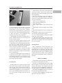
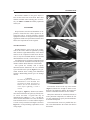
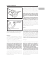
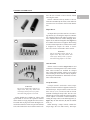
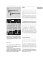
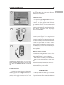
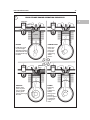
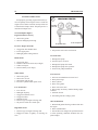
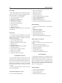
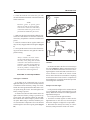
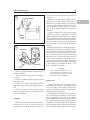
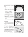
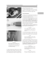
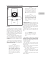
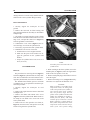
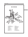
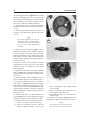
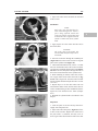
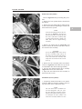
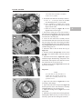
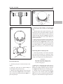
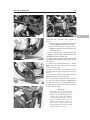
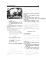
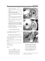
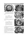
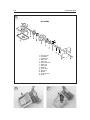
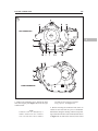
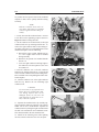
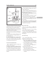
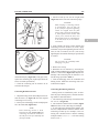
SERIAL NUMBERS
Serial numbers and model codes are stamped into
the motorcycle and/or printed on labels.
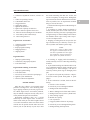
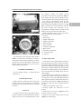
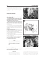
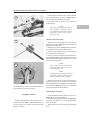
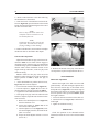
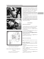
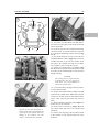
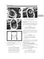
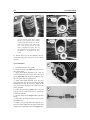
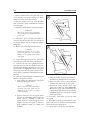
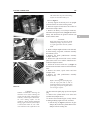
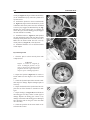
The VIN or vehicle identification number (Fig
-
ure 1) appears on a label on the inside of the left
fork leg. This number is also stamped on the right
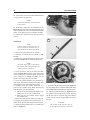
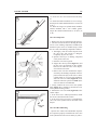
side of the steering head (Figure 2). Yamaha’s pri
-
mary ID number is a variation of the VIN number.
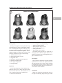
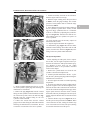
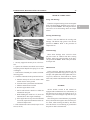
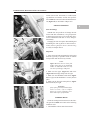
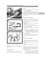
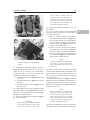
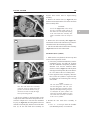
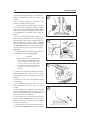
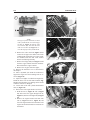
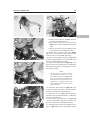
The model code (Figure 3) appears on a label on
the side of the right main frame tube.
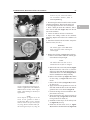
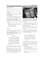
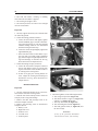
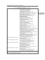
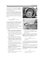
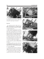
The engine number (Figure 4) is stamped on the
right side of the upper crankcase.
GENERAL INFORMATION 3
1
1

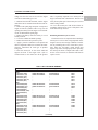
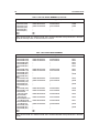
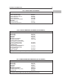
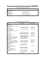
Record these numbers in the Quick Reference
Data section at the front of the book. Have these
numbers available when ordering parts. If neces
-
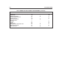
sary, use Table 1 and Table 2 to identify a particular
motorcycle.
FASTENERS
Proper fastener selection and installation is im
-
portant to ensure that the vehicle operates as de
-
signed and can be serviced efficiently. Original
equipment fasteners are designed for their specific
applications. Make sure replacement fasteners meet
all the same requirements as the originals.
Threaded Fasteners
Threaded fasteners secure most of the compo
-
nents on the vehicle. Most are tightened by turning
them clockwise (right-hand threads). If the normal
rotation of the component would loosen the fas-
tener, it may have left-hand threads. If a left-hand
threaded fastener is used, it is noted in the text.
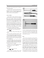
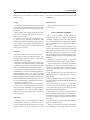
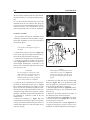
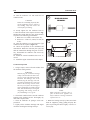
Two dimensions are required to match the thread
size of the fastener: the number of threads in a given
distance and the outside diameter of the threads.
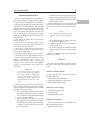
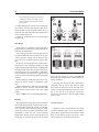
Two systems are currently used to specify
threaded fastener dimensions: the U.S. standard
system and the metric system (Figure 5). Pay par
-
ticular attention when working with unidentified
fasteners. Mismatching thread types can damage
threads.
CAUTION
To ensure the fastener threads are not
mismatched or cross threaded, start
all fasteners by hand. If a fastener is
hard to start or turn, determine the
cause before tightening it with a
wrench.
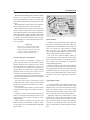
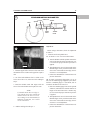
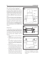
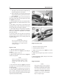
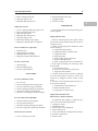
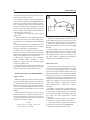
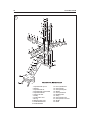
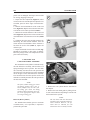
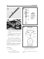
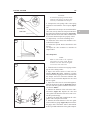
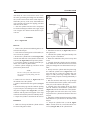
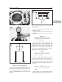
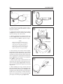
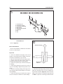
The length (L, Figure 6), diameter (D) and dis
-
tance between thread crests (pitch) (T) classify met
-
ric screws and bolts. A typical bolt may be
identified by the numbers, 8—1.25 × 130. This in
-
dicates the bolt has diameter of 8 mm, the distance
between thread crests is 1.25 mm and the length is
130 mm. Always measure bolt length as shown in
Figure 6 to avoid purchasing replacements of the
wrong length.
The numbers located on the top of the fastener
(Figure 6) indicate the strength of metric screws
and bolts. The higher the number, the stronger the
fastener. Unnumbered fasteners are the weakest.
Many bolts and studs are combined with nuts to
secure particular components. To indicate the size
of a nut, manufacturers specify the internal diame
-
ter and the thread pitch.
The measurement across two parallel flats on a
nut or bolt head indicates the wrench size that fits
the fastener.
4 CHAPTER ONE
2
3
4

WARNING
Do not install fasteners with a
strength classification lower than
what was originally installed by the
manufacturer. Doing so may cause
equipment failure and/or damage.
Torque Specifications
The components of the motorcycle may be sub
-
jected to uneven stresses if the fasteners of the vari
-
ous subassemblies are not installed and tightened
correctly. Fasteners that are improperly installed or
that work loose can cause extensive damage. Use an
accurate torque wrench when tightening fasteners,
and tighten each fastener to its specified torque.
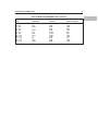
Torque specifications for specific components
appear in the procedures and at the end of the appro
-
priate chapters. Specifications for torque are pro
-
vided in Newton-meters (N•m), foot-pounds
(ft.-lb.) and inch-pounds (in.-lb.). Refer to Table 7
for torque conversion factors and to Table 6 for
general torque specifications. To use the general
torque table, first determine the size of the fastener
as described in Threaded Fasteners in this section.
Locate that size fastener in Table 6, and tighten the
fastener to the indicated torque. Torque wrenches
are described under Basic Tools in this chapter.
Self-Locking Fasteners
Several types of bolts, screws and nuts use vari
-
ous means to create interference between the
threads of two fasteners to prevent the fasteners
from loosening. The most common types are the ny
-
lon-insert nut or a dry adhesive coating on the
threads of a bolt.
Self-locking fasteners improve resistance to vi-
bration and therefore provide greater holding
strength than standard fasteners. Most self-locking
fasteners cannot be reused. The materials used to
form the lock become distorted after the initial in-
stallation and removal. Always discard and replace
self-locking fasteners after their removal. Do not re-
place self-locking fasteners with standard fasteners.
Washers
There are two basic types of washers: flat wash
-
ers and lockwashers. Flat washers are simple discs
with a hole for a screw or bolt. Flat washers help
distribute fastener load, they protect components
from fastener damage, and they can be used as spac
-
ers and seals. Lockwashers are used to prevent a
fastener from working loose.
When replacing washers, make sure the replace
-
ments are of the same design and quality as the orig
-
inals.
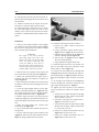
Cotter Pins
A cotter pin is a split metal pin inserted into a hole
or slot to prevent a fastener from working loose. In
certain applications, such as the rear axle on an ATV
or motorcycle, a cotter pin and castellated (slotted)
nut is used.
GENERAL INFORMATION 5
1
5
U.S. Standard Metric
60°
60°
6
Grade marking
-9.8
T
L
D

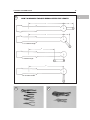
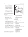
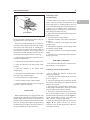
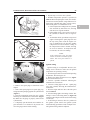
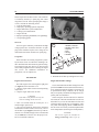
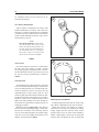
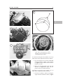
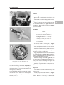
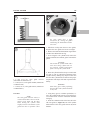
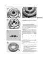
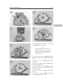
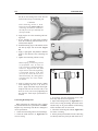
To use a cotter pin, first make sure the pin’s diam
-
eter is correct for the hole in the fastener. After cor
-
rectly tightening the fastener and aligning the holes,
insert the cotter pin through the hole and bend the
ends over the fastener (Figure 7). Unless instructed
to do so, never loosen a torqued fastener to align the
holes. If the holes do not align, tighten the fastener
just enough to achieve alignment.
Cotter pins are available in various diameters and
lengths. Measure length from the bottom of the
head to the tip of the shortest pin.
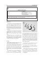
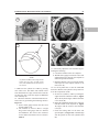
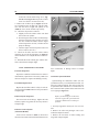
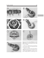
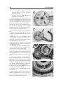
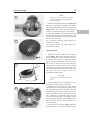
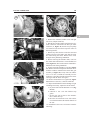
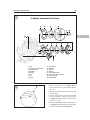
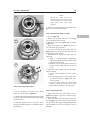
Snap Rings and E-clips
Snap rings (Figure 8) are circular-shaped metal
retaining clips. They secure parts and gears onto
shafts, pins or rods. External type snap rings are
used to retain items on shafts. Internal type snap
rings secure parts within housing bores. In some ap-
plications, in addition to securing the compo-
nent(s), snap rings of varying thickness also
determine endplay. These are usually called
selective snap rings.
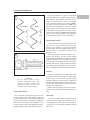
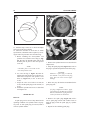
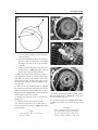
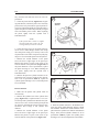
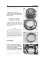
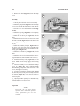
Two basic types of snap rings are used: machined
and stamped snap rings. Machined snap rings (Fig-
ure 9) can be installed in either direction since both
faces have sharp edges. Stamped snap rings (Figure
10) are manufactured with a sharp edge and a round
edge. When installing a stamped snap ring in a
thrust application, install the sharp edge facing
away from the part producing the thrust.
E-clips are used when it is not practical to use a
snap ring. Remove E-clips with a flat blade screw
-
driver by prying between the shaft and E-clip. To in
-
stall an E-clip, center it over the shaft groove, and
push or tap it into place.
Observe the following when installing snap
rings:
1. Remove and install snap rings with snap ring pli
-
ers. See Snap Ring Pliers in this chapter.
2. In some applications, it may be necessary to re
-
place snap rings after removing them.
3. Compress or expand snap rings only enough to
install them. If overly expanded, they lose their re
-
taining ability.
4. After installing a snap ring, make sure it seats
completely.
5. Wear eye protection when removing and install
-
ing snap rings.
SHOP SUPPLIES
Lubricants and Fluids
Periodic lubrication helps ensure a long service
life for any type of equipment. Using the correct
type of lubricant is as important as performing the
lubrication service, although in an emergency the
wrong type of lubricant is better than none. The fol
-
lowing section describes the types of lubricants
6 CHAPTER ONE
7
Correct installation
of cotter pin
8
Internal snap ring Plain circlip
External snap ring
E-clip

most often required. Make sure to follow the manu-
facturer’s recommendations for lubricant types.
Engine oils
Generally, all liquid lubricants are called oil.
They may be mineral-based (including petroleum
bases), natural-based (vegetable and animal bases),
synthetic-based, or emulsions (mixtures).
Engine oil is classified by two standards: the
American Petroleum Institute (API) service classi
-
fication and the Society of Automotive Engineers
(SAE) viscosity rating. This information is on the
oil container label. Two letters indicate the API ser
-
vice classification (SF, SG, etc.). The number or se
-
quence of numbers and letter (10W-40 for example)
is the oil’s viscosity rating. The API service classifi
-
cation and the SAE viscosity index are not
indications of oil quality.
The service classification indicates that the oil
meets specific lubrication standards. The first letter
in the classification (S) indicates that the oil is for
gasoline engines. The second letter indicates the
standard the oil satisfies.
Always use an oil with a classification recom
-
mended by the manufacturer. Using an oil with a
different classification can cause engine damage.
Viscosity is an indication of the oil’s thickness.
Thin oils have a lower number while thick oils have
a higher number. A W after the number indicates
that the viscosity testing was done at low tempera
-
ture to simulate cold-weather operation. Engine oils
fall into the 5- to 50-weight range for single-grade
oils.
Most manufacturers recommend multigrade oil.
Multigrade oils (10W-40, for example) are less vis
-
cous (thinner) at low temperatures and more vis
-
cous (thicker) at high temperatures. This allows the
oil to perform efficiently across a wide range of en
-
gine operating conditions. The lower the number,
the better the engine will start in cold climates.
Higher numbers are usually recommended when
operating an engine in hot weather.
Greases
Grease is an oil to which a thickening base has
been added so the end product is semi-solid. Grease
is often classified by the type of thickener added,
such as lithium soap. The National Lubricating
Grease Institute (NLGI) grades grease. Grades
range from No. 000 to No. 6, with No. 6 being the
thickest. Typical multipurpose grease is NLGI No.
2. For specific applications, manufacturers may rec
-
ommend a water-resistant type grease or one with
an additive such as molybdenum disulfide (MoS
2
).
Brake fluid
Brake fluid is the hydraulic fluid used to transmit
hydraulic pressure (force) to the wheel brakes.
Brake fluid is classified by the Department of
Transportation (DOT). Current designations for
brake fluid are DOT 3, DOT 4 and DOT 5. This
classification appears on the fluid container.
Each type of brake fluid has its own definite char
-
acteristics. Do not intermix different types of brake
fluid. DOT 5 fluid is silicone-based. DOT 5 is not
compatible with other fluids or in systems for which
it was not designed. Mixing DOT 5 fluid with other
fluids may cause brake system failure. When add
-
ing brake fluid, only use the fluid recommended by
the vehicle manufacturer.
GENERAL INFORMATION 7
1
10
Rounded edges
Sharp edges
Direction of thrust
9
Full support
areas
Direction
of thrust

Brake fluid will damage plastic, painted or plated
surfaces. Use extreme care when working with
brake fluid. Immediately clean up any spills with
soap and water. Rinse the area with plenty of clean
water.
Hydraulic brake systems require clean and mois
-
ture-free brake fluid. Never reuse brake fluid.
Brake fluid absorbs moisture, which greatly re
-
duces its ability to perform correctly. Keep brake
fluid containers and reservoirs properly sealed. Pur
-
chase brake fluid in small containers, and discard
any small leftover quantities properly. Do not store
a container of brake fluid with less than 1/4 of the
fluid remaining. This small amount absorbs mois
-
ture very rapidly.
WARNING
Never put a mineral based (petro
leum) oil into the brake system. Min
eral oil will cause rubber parts in the
system to swell and break apart, re
sulting in complete brake failure.
Cleaners, Degreasers and Solvents
Many chemicals are available to remove oil,
grease and other residue from the vehicle. Before
using cleaning solvents, consider how they will be
used and disposed of, particularly if they are not
water-soluble. Local ordinances may require spe-
cial procedures for the disposal of various cleaning
chemicals. Refer to Safety and Cleaning Parts in
this chapter for more information on their use.
Generally, degreasers are strong cleaners used to
remove heavy accumulations of grease from engine
and frame components.
Use brake parts cleaner to clean brake system
components when contact with petroleum-based
products will damage seals. Brake parts cleaner
leaves no residue.
Use electrical contact cleaner to clean electrical
connections and components without leaving any
residue.
Carburetor cleaner is a powerful solvent used to
remove fuel deposits and varnish from fuel system
components. Use this cleaner carefully, as it may
damage finishes.
Most solvents are designed to be used in a parts
washing cabinet for individual component clean
-
ing. For safety, use only nonflammable or high flash
point solvents.
Gasket Sealant
Sealants are used in combination with a gasket or
seal and are occasionally used alone. Follow the
manufacturer’s recommendation when using seal
-
ants. Use extreme care when choosing a sealant
other than the type originally recommended.
Choose sealants based on their resistance to heat,
various fluids and their sealing capabilities.
One of the most common sealants is RTV, or
room temperature vulcanizing sealant. This sealant
cures at room temperature over a specific time pe-
riod. It allows the repositioning of components
without damaging gaskets.
Moisture in the air causes the RTV sealant to
cure. Always install the tube cap as soon as possible
after applying RTV sealant. RTV sealant has a lim
-
ited shelf life and will not cure properly if the shelf
life has expired. Keep partial tubes sealed, and dis
-
card them if they have surpassed the expiration
date.
Applying RTV sealant
Clean all old gasket residue from the mating sur
-
faces. Remove all gasket material from blind
threaded holes; it can cause inaccurate bolt torque.
Spray the mating surfaces with aerosol parts
cleaner, and then wipe them with a lint-free cloth.
The area must be clean for the sealant to adhere.
Apply RTV sealant in a continuous bead, 2-3 mm
(0.08-0.12 in.) thick. Circle all the fastener holes
unless otherwise specified. Do not allow any seal
-
ant to enter these holes. Assemble and tighten the
fasteners to the specified torque within the time
frame recommended by the RTV sealant manufac
-
turer.
8 CHAPTER ONE
11

Gasket Remover
Aerosol gasket remover can help remove stub
-
born gaskets. This product can speed up the re
-
moval process and prevent damage to the mating
surface that may be caused by a scraping tool. Most
of these products are very caustic. Follow the gasket
remover manufacturer’s instructions for use.
Threadlocking Compound
A threadlocking compound is a fluid applied to
the threads of fasteners. After tightening the fas-
tener, the fluid dries and becomes a solid filler be-
tween the threads. This makes it difficult for the
fastener to work loose from vibration or heat expan-
sion and contraction. Some threadlocking com
-
pounds also provide a seal against fluid leaks.
Before applying threadlocking compound, re
-
move any old compound from both thread areas and
clean them with aerosol parts cleaner. Use the com
-
pound sparingly. Excess fluid can run into adjoin
-
ing parts.
Threadlocking compounds are available in vari
-
ous strength, temperature and repair applications.
Follow the manufacturer’s recommendations re
-
garding compound selection.
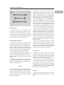
TOOLS
Most of the procedures in this manual can be car
-
ried out with simple hand tools and test equipment
familiar to the home mechanic. Always use the cor
-
rect tools for the job at hand. Keep tools organized
and clean. Store them in a tool chest with related
tools organized together.
Quality tools are essential. The best are con
-
structed of high-strength alloy steel. These tools are
light, easy to use and resistant to wear. Their working
surface is smooth, and the tool is carefully polished.
They have an easy-to-clean finish and are comfort
-
able to use. Quality tools are a good investment.
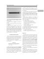
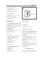
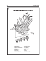
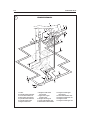
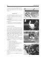
When building a new tool kit, consider purchas
-
ing a basic set (Figure 11) from a large tool sup
-
plier. These sets contain a variety of commonly
used tools, and they provide substantial savings
when compared to individually purchased tools. As
one becomes more experienced and tasks become
more complicated, specialized tools can be added.
Some of the procedures call for special tools. In
most cases, the tool is illustrated in use. It may be
possible to substitute similar tools or fabricate a
suitable replacement. However, in some cases, the
specialized equipment may make it impractical for
the home mechanic to perform the procedure. When
necessary, such operations are identified in the text.
It may be less expensive to have a professional per-
form these tasks, especially if the cost of the
equipment is high.
In the case of Yamaha special tools, two part
numbers are listed. The part number for special
tools sold in the United States begin with a two let-
ter prefix, for example: YM-90069. Part numbers
for tools sold in Europe and Australia markets begin
with a number, for example: 90890-01290.
Screwdrivers
Screwdrivers of various lengths and types are
mandatory for the simplest tool kit. The two basic
types are the slotted tip (flat blade) and the Phillips
tip. These are available in sets that often include an
assortment of tip sizes and shaft lengths.
As with all tools, use a screwdriver designed for
the job. Make sure the size of the tip conforms to the
size and shape of the fastener. Use them only for
driving screws. Never use a screwdriver for prying
or chiseling metal. Repair or replace worn or dam
-
aged screwdrivers. A worn tip may damage the fas
-
tener, making it difficult to remove.
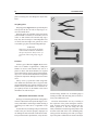
Wrenches
Box-end, open-end and combination wrenches
(Figure 12) are available in a variety of types and
sizes.
GENERAL INFORMATION 9
1
12

The number stamped on the wrench refers to the
distance between the work areas. This must match
the distance across two parallel flats on the bolt
head or nut.
The box-end wrench is an excellent tool because
it grips the fastener on all sides. This reduces the
chance of the tool slipping. The box-end wrench is
designed with either a 6- or 12-point opening. For
stubborn or damaged fasteners, the 6-point provides
superior holding ability by contacting the fastener
across a wider area at all six edges. For general use,
the 12-point works well. It allows the wrench to be
removed and reinstalled without moving the handle
over such a wide arc.
An open-end wrench is fast and works best in ar
-
eas with limited overhead access. Because it con
-
tacts the fastener at only two points, an open-end
wrench is subject to slipping under heavy force or if
the tool or fastener is worn. A box-end wrench is
preferred in most instances, especially when apply-
ing considerable force to a fastener.
The combination wrench has a box-end on one
end and an open-end on the other. This combination
makes it a very convenient tool.
Adjustable Wrenches
An adjustable wrench or Crescent wrench (Fig-
ure 13) fits nearly any nut or bolt head that has clear
access around its entire perimeter. An adjustable
wrench is best used as a backup wrench to hold a
large nut or bolt while the other end is being loos
-
ened or tightened with a box-end or socket wrench.
Adjustable wrenches contact the fastener at only
two points, which makes them more subject to slip
-
ping off the fastener. The fact that one jaw is adjust
-
able and may loosen only aggravates this
shortcoming. Make certain the solid jaw is the one
transmitting the force.
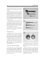
Socket Wrenches, Ratchets and Handles
Sockets that attach to a ratchet handle (Figure
14) are available with 6-point (A, Figure 15)or
12-point (B) openings and different drive sizes. The
drive size indicates the size of the square hole that
accepts the ratchet handle. The number stamped on
the socket is the size of the work area and must
match the fastener head.
As with wrenches, a 6-point socket provides su
-
perior-holding ability, while a 12-point socket
needs to be moved only half as far to reposition it on
the fastener.
Sockets are designated for use with either hand.
Impact sockets are made of thicker material for
more durability. Compare the size and wall thick
-
ness of a 19-mm hand socket (A, Figure 16) and the
19-mm impact socket (B). Use impact sockets when
using an impact driver or air tools. Use hand sockets
with hand-driven attachments.
10 CHAPTER ONE
13
14
15

WARNING
Do not use hand sockets with air or
impact tools. They may shatter and
cause injury. Always wear eye protec
tion when using impact or air tools.
Various handles are available for sockets. The
speed handle is used for fast operation. Flexible
ratchet heads in varying lengths allow the socket to
be turned with varying force and at odd angles. Ex
-
tension bars allow the socket setup to reach difficult
areas. The ratchet is the most versatile wrench. It al
-
lows the user to install or remove the nut without
removing the socket.
Sockets combined with any number of drivers
make them undoubtedly the fastest, safest and most
convenient tool for fastener removal and installa
-
tion.
Impact Driver
An impact driver provides extra force for remov
-
ing fasteners by converting the impact of a hammer
into a turning motion. This makes it possible to re
-
move stubborn fasteners without damaging them.
Impact drivers and interchangeable bits (Figure 17)
are available from most tool suppliers. When using
a socket with an impact driver, make sure the socket
is designed for impact use. Refer to Socket
Wrenches, Ratchets and Handles in this section.
WARNING
Do not use hand sockets with air or
impact tools, They may shatter and
cause injury. Always wear eye protec
tion when using impact or air tools.
Allen Wrenches
Allen or setscrew wrenches (Figure 18) are used
on fasteners with hexagonal recesses in the fastener
head. These wrenches are available in L-shaped
bars, sockets and T-handles. A metric set is required
when working on most vehicles made by Japanese
and European manufacturers. Allen bolts are some
-
times called socket bolts.
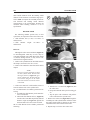
Torque Wrenches
A torque wrench is used with a socket, torque
adapter or similar extension to tighten a fastener to a
measured torque. Torque wrenches come in several
drive sizes (1/4, 3/8, 1/2 and 3/4) and use various
methods of reading the torque value. The drive size
indicates the size of the square drive that accepts the
socket, adapter or extension. Common methods of
reading the torque value are the deflecting beam (A,
Figure 19), the dial indicator (B) and the audible
click (C).
When choosing a torque wrench, consider the
torque range, drive size and accuracy. The torque
GENERAL INFORMATION 11
1
16
17
18

specifications in this manual provide an indication
of the range required.
A torque wrench is a precision tool that must be
properly cared for to remain accurate. Store torque
wrenches in cases or separate padded drawers
within a toolbox. Follow the manufacturer’s in
-
structions for their care and calibration.
Torque Adapters
Torque adapters extend or reduce the reach of a
torque wrench. The torque adapter shown in Figure
20 is used to tighten a fastener that cannot be
reached due to the size of the torque wrench head,
drive, and socket. Since a torque adapter changes
the effective lever length (Figure 21) of a torque
wrench, the torque reading on the wrench does not
equal the actual torque applied to the fastener. It is
necessary to calculate the adjusted torque reading
on the wrench to compensate for the change of lever
length. When a torque adapter is used at a right an-
gle to the drive head, calibration is not required,
since the effective length has not changed.
To calculate the adjusted torque reading when us-
ing a torque adapter, use the following formula.
TW = TA × L
L+A
TW is the torque setting or dial reading on the
wrench.
TA is the torque specification and the actual
amount of torque that will be applied to the fastener.
A is the amount that the adapter increases (or in
some cases reduces) the effective lever length as
measured along the centerline of the torque wrench
from the center of the drive to the center of adapter
box end (Figure 21).
L is the lever length of the wrench as measured
from the center of the drive to the center of the grip.
The effective length of the torque wrench is mea
-
sured along the centerline of the torque wrench as is
the sum of L and A. For example:
To apply 20 ft.-lb. to a fastener using an adapter
as shown in the top example in Figure 21.
TA = 20 ft.-lb.
A = 3 in.
L = 14 in.
TW=20×14
= 280 = 16.5 ft. lb.
14+3 17
In this example, a click-type torque wrench
would be set to the calculated torque value (TW =
16.5 ft.-lb.) . When using a dial or beam-type torque
wrench, tighten the fastener until the pointer aligns
with 16.5 ft.-lb. In either case, although the torque
wrench reads 16.5 ft.-lb., the actual torque applied
to the fastener is 20 ft.-lb.
Pliers
Pliers come in a wide range of types and sizes.
Pliers are useful for holding, cutting, bending, and
crimping. Do not use them to turn fasteners. Figure
22 shows several types of useful pliers. Each design
has a specialized function. Slip-joint pliers are gen
-
eral-purpose pliers used for gripping and bending.
Diagonal cutting pliers cut wire and can be used to
remove cotter pins. Adjustable pliers can be ad
-
justed to hold different size objects. The jaws re
-
main parallel so they grip around objects such as
pipe or tubing. Needlenose pliers are used to hold or
bend small objects. Locking pliers (Figure 23),
sometimes called vise-grips, are used to hold ob
-
jects very tightly. They have many uses ranging
from holding two parts together to gripping the end
of a broken stud. Use caution when using locking
12 CHAPTER ONE
19
20

GENERAL INFORMATION 13
1
21
HOW TO MEASURE TORQUE WRENCH EFFECTIVE LENGTH
L
L
L
L
L + A = Effective length
L = Effective length
No calculation needed
A
A
22 23

pliers. The sharp jaws will damage the objects they
hold.
Snap
Ring Pliers
Snap ring pliers (Figure 24) are specialized pliers
with tips that fit into the ends of snap rings to re
-
move and install them.
Snap ring pliers are available with a fixed action
(either internal or external) or convertible (one tool
works on both internal and external snap rings).
They may have fixed tips or interchangeable ones
of various sizes and angles. For general use, select
convertible type pliers with interchangeable tips.
WARNING
Snap rings can slip and fly off during
removal and installation. In addition,
the tips may break. Always wear eye
protection when using snap ring pli
ers.
Hammers
Various types of hammers (Figure 25) are avail-
able to fit a number of applications. A ball-peen
hammer is used to strike another tool, such as a
punch or chisel. Soft-faced hammers are required
when a metal object must be struck without damag-
ing it. Never use a metal-faced hammer on engine or
suspension components. Damage will occur in most
cases.
Always wear eye protection when using ham
-
mers. Make sure the hammer face is in good condi
-
tion and the handle is not cracked. Select the correct
hammer for the job and make sure to strike the ob
-
ject squarely. Do not use the handle or the side of
the hammer to strike an object.
PRECISION MEASURING TOOLS
Each type of measuring instrument is designed to
measure a dimension with a particular degree of ac
-
curacy and within a certain range. When selecting a
measuring tool, make sure it is applicable to the
task.
As with all tools, measuring tools provide the best
results if they are cared for properly. Improper use
can damage the tool and result in inaccurate results.
If any measurement is questionable, verify the mea
-
surement using another tool. A standard gauge is
usually provided with measuring tools to check ac
-
curacy and calibrate the tool.
Precision measurements can vary according to
the experience of the person taking the measure
-
ment. Accurate results are only possible if the me
-
chanic possesses a feel for using the tool.
Heavy-handed use of measuring tools produces less
accurate results than if the tool is handled gently.
Grasp precision measuring tools with your finger
-
tips so the point at which the tool contacts the object
14 CHAPTER ONE
24
25
26

is easily felt. This feel for the equipment produces
consistently accurate measurements and reduces
the risk of damaging the tool or component. Refer to
the following sections for a description of various
measuring tools.
Feeler Gauge
The feeler or thickness gauge (Figure 26) is used
for measuring the distance between two surfaces. A
common use for a feeler gauge is to measure valve
clearance. Wire (round) type gauges are used to
measure spark plug gap.
A feeler gauge set consists of an assortment of
steel strips of graduated thicknesses. Each blade is
marked with its thickness. Blades can be of various
lengths and angles for different procedures.
Calipers
Calipers (Figure 27) are excellent tools for ob
-
taining inside, outside and depth measurements. Al
-
though not as precise as a micrometer, they allow
reasonable precision, typically to within 0.05 mm
(0.001 in.). Most calipers have a range up to 150
mm (6 in.).
Calipers are available in dial, vernier or digital
versions. Dial calipers have a dial, which is easy to
read. Vernier calipers have marked scales that must
be compared to determine the measurement. The
digital caliper uses an LCD display to show the
measurement.
Properly maintain the measuring surfaces of the
caliper. There must not be any dirt or burrs between
the tool and the object being measured. Never force
the caliper closed around an object. Close the cali-
per around the highest point so it can be removed
with a slight drag. Some calipers require calibra-
tion. Always refer to the manufacturer’s instruc-
tions when using a new or unfamiliar caliper.
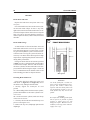
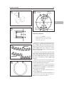
Figure 28 shows a measurement taken with a
metric vernier caliper. To read the measurement,
note that the fixed scale is graduated in centimeters,
which is indicated by the whole numbers 1, 2, 3 and
so on. Each centimeter is then divided into millime-
ters, which are indicated by the small line between
the whole numbers. (1 centimeter equals 10 milli
-
meters). The movable scale is marked in increments
of 0.05 (hundredths) mm. The value of a measure
-
ment equals the reading on the fixed scale plus the
reading on the movable scale.
To determine the reading on the fixed scale, look
for the line on the fixed scale immediately to the left
of the 0-line on the movable scale. In Figure 28, the
fixed scale reading is 1 centimeter (or 10 millime
-
ters).
To determine the reading on the movable scale,
note the one line on the movable scale that precisely
aligns with a line on the fixed scale. Look closely. A
number of lines will seem close, but only one aligns
precisely with a line on the fixed scale. In Figure
28, the movable scale reading is 0.50 mm.
To calculate the measurement, add the fixed scale
reading (10 mm) to the movable scale reading (0.50
mm) for a value of 10.50 mm.
GENERAL INFORMATION 15
1
27
28
10.00 mm
0.50 mm
10.50 mm
Moveable scales
Fixed
scale
0.400 in
.
0.013 in.
0.413 in.

Micrometers
A micrometer is an instrument designed for linear
measurement using the decimal divisions of the
inch or meter (Figure 29). While there are many
types and styles of micrometers, most of the proce-
dures in this manual call for an outside micrometer.
The outside micrometer is used to measure the out-
side diameter of cylindrical forms and the thickness
of materials.
A micrometer’s size indicates the minimum and
maximum size it can measure. The usual sizes
(Figure 30) are 0-1 in. (0-25 mm), 1-2 in. (25-50
mm), 2-3 in. (50-75 mm) and 3-4 in. (75-100
mm).
Micrometers that cover a wider range of mea
-
surement are available. These use a large frame with
interchangeable anvils of various lengths. This type
of micrometer offers a cost savings; however, its
overall size may make it less convenient.
Reading
When reading a micrometer, read numbers from
different scales and add them together.
For accurate results, properly maintain the mea
-
suring surfaces of the micrometer. There must not
be any dirt or burrs between the tool and the mea
-
sured object. Never force the micrometer closed
around an object. Close the micrometer around the
highest point so it can be removed with a slight
drag.
The standard metric micrometer (Figure 31)is
accurate to one one-hundredth of a millimeter
(0.01-mm). The sleeve line is graduated in millime
-
ter and half millimeter increments. The marks on
the upper half of the sleeve line equal 1.00 mm. Ev
-
ery fifth mark above the sleeve line is identified
with a number. The number sequence depends on
the size of the micrometer. A 0-25 mm micrometer,
for example, has sleeve marks numbered 0 through
25, in 5 mm increments. This numbering sequence
continues with larger micrometers. On all metric
micrometers, each mark on the lower half of the
sleeve equals 0.50 mm.
The tapered end of the thimble has fifty lines
marked around it. Each mark equals 0.01 mm.
One complete turn of the thimble aligns its 0
mark with the first line on the lower half of the
sleeve line or 0.50 mm.
When reading a metric micrometer, add the num
-
ber of millimeters and half-millimeters on the
sleeve line to the hundredths of a millimeter shown
on the thimble. Perform the following steps and re
-
fer to Figure 32.
16 CHAPTER ONE
DECIMAL PLACE VALUES*
0.1 Indicates 1/10 (one tenth of an inch
or millimeter)
0.010 Indicates 1/100 (one one-hundreth of
an inch or millimeter)
0.001 Indicates 1/1,000 (one one-thousandth
of an inch or millimeter)
*This chart represents the values of figures placed to the right of the decimal point. Use it when
reading decimals from one-tenth to one one-thousandth of an inch or millimeter. It is not a con-
version chart (for example: 0.001 in. is not equal to 0.001 mm).
29
30

1. Read the upper half of the sleeve line and count
the number of lines visible. Each upper line equals 1
mm.
2. See if the half-millimeter line is visible on the
lower sleeve line. If so, add 0.50 to the reading in
Step 1.
3. Read the thimble mark that aligns with the
sleeve line. Each thimble mark equals 0.01 mm.
NOTE
If a thimble mark does not align ex
actly with the sleeve line, estimate the
amount between the lines. For accu
rate readings to two thousandths of a
millimeter (0.002 mm), use a metric
vernier micrometer.
4. Add the readings from Steps 1-3.
Adjustment
Before using a micrometer, check its adjustment
as follows:
1. Clean the anvil and spindle faces.
2A. To check a 0-1 in. or 0-25 mm micrometer:
a. Turn the thimble until the spindle contacts the
anvil. If the micrometer has a ratchet stop, use
it to ensure the proper amount of pressure is
applied.
b. The adjustment is correct if the 0 mark on the
thimble aligns exactly with the 0 mark on the
sleeve line. If the marks do not align, the mi
-
crometer is out of adjustment.
c. Follow the manufacturer’s instructions to ad
-
just the micrometer.
2B. To check a micrometer larger than 1 in. or 25
mm, use the standard gauge supplied by the manu
-
facturer. A standard gauge is a steel block, disc or
rod that is machined to an exact size.
a. Place the standard gauge between the spindle
and anvil, and measure its outside diameter or
length. If the micrometer has a ratchet stop,
use it to ensure the proper amount of pressure
is applied.
b. The adjustment is correct if the 0 mark on the
thimble aligns exactly with the 0 mark on the
sleeve line. If the marks do not align, the mi
-
crometer is out of adjustment.
c. Follow the manufacturer’s instructions to ad
-
just the micrometer.
GENERAL INFORMATION 17
1
31
STANDARD METRIC MICROMETER
Anvil
Spindle
Locknut
Sleeve line
Thimble
Rachet
Thimble
marks
Sleeve
marks
32
5.00 mm
0.50 mm
0.18 mm
5.68 mm

Care
Micrometers are precision instruments. They
must be used and maintained with great care.
Note the following:
1. Store micrometers in protective cases or separate
padded drawers in a toolbox.
2. When in storage, make sure the spindle and anvil
faces do not contact each other or any other objects.
If they do, temperature changes and corrosion may
damage the contact faces.
3. Do not clean a micrometer with compressed air.
Dirt forced into the tool will cause wear.
4. Lubricate micrometers with WD-40 to prevent
corrosion.
Telescoping and Small Bore Gauges
Use telescoping gauges (Figure 33) and small
bore gauges (Figure 34) to measure bores. Neither
gauge has a scale for direct readings. An outside mi-
crometer must be used to determine the reading.
To use a telescoping gauge, select the correct size
gauge for the bore. Compress the movable post and
carefully insert the gauge into the bore. Carefully
move the gauge in the bore to make sure it is cen-
tered. Tighten the knurled end of the gauge to hold
the movable post in position. Remove the gauge,
and measure the length of the posts with a microme-
ter. Telescoping gauges are typically used to mea
-
sure cylinder bores.
To use a small-bore gauge, select the correct size
gauge for the bore. Carefully insert the gauge into
the bore. Tighten the knurled end of the gauge to
carefully expand the gauge fingers to the limit
within the bore. Do not overtighten the gauge, as
there is no built-in release. Excessive tightening can
damage the bore surface and damage the tool. Re
-
move the gauge and measure the outside dimension
(Figure 35). Small bore gauges are typically used to
measure valve guides.
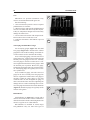
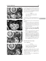
Dial Indicator
A dial indicator (A, Figure 36) is a gauge with a
dial face and needle used to measure variations in
dimensions and movements. Measuring brake rotor
runout is a typical use for a dial indicator.
Dial indicators are available in various ranges
and graduations. They use three basic types of
18 CHAPTER ONE
33
34
35
36

mounting bases: magnetic, clamp, or screw-in stud.
When purchasing a dial indicator, select the mag
-
netic stand type (B, Figure 36) with a continuous
dial.
Cylinder Bore Gauge
A cylinder bore gauge is similar to a dial indica
-
tor. The gauge set shown in Figure 37 consists of a
dial indicator, handle, and different length adapters
(anvils) to fit the gauge to various bore sizes. The
bore gauge is used to measure bore size, taper and
out-of-round. When using a bore gauge, follow the
manufacturer’s instructions.
Compression Gauge
A compression gauge (Figure 38) measures com
-
bustion chamber (cylinder) pressure, usually in psi
or kg/cm
2
. The gauge adapter is either inserted or
screwed into the spark plug hole to obtain the read
-
ing. Disable the engine so it will not start and hold
the throttle in the wide-open position when per
-
forming a compression test. An engine that does not
have adequate compression cannot be properly
tuned. See Chapter Three.
Multimeter
A multimeter (Figure 39) is an essential tool for
electrical system diagnosis. The voltage function
indicates the voltage applied or available to various
electrical components. The ohmmeter function tests
circuits for continuity and measures the resistance
of a circuit.
Some test specifications for electrical compo-
nents are based on results using a specific test meter.
Results may vary if a meter not recommend by the
manufacturer is used. Such requirements are noted
when applicable.
Ohmmeter (analog) calibration
Each time an analog ohmmeter is used or if the
scale is changed, the ohmmeter must be calibrated.
Digital ohmmeters do not require calibration.
1. Make sure the meter battery is in good condition.
2. Make sure the meter probes are in good condi
-
tion.
3. Touch the two probes together and watch the
needle. It should align with the 0 mark on the scale.
4. If necessary, rotate the set-adjust knob until the
needle points directly to the 0 mark.
ELECTRICAL SYSTEM
FUNDAMENTALS
A thorough study of the many types of electrical
systems used in today’s vehicles is beyond the
scope of this manual. However, an understanding of
GENERAL INFORMATION 19
1
37
38
39

electrical basics is necessary to perform simple
diagnostic tests.
Voltage
Voltage is the electrical potential or pressure in an
electrical circuit and is expressed in volts. The more
pressure (voltage) in a circuit, the more work can be
performed.
Direct current (DC) voltage means the electricity
flows in one direction. All circuits powered by a
battery are DC circuits.
Alternating current (AC) means that the electric
-
ity flows in one direction momentarily then
switches to the opposite direction. Alternator output
is an example of AC voltage. This voltage must be
changed or rectified to direct current to operate in a
battery powered system.
Resistance
Resistance is the opposition to the flow of elec-
tricity within a circuit or component and is mea-
sured in ohms. Resistance causes a reduction in
available current and voltage.
Resistance is measured in an inactive circuit with
an ohmmeter. The ohmmeter sends a small amount
of current into the circuit and measures how diffi-
cult it is to push the current through the circuit.
An ohmmeter, although useful, is not always a
good indicator of a circuit’s actual ability under op
-
erating conditions. This is due to the low voltage
(6-9 volts) that the meter uses to test the circuit. The
voltage in an ignition coil secondary winding can be
several thousand volts. Such high voltage can cause
the coil to malfunction, yet the fault may not be de
-
tected during a resistance test.
Resistance generally increases with temperature.
Perform all tests with the component or circuit at
room temperature. Resistance tests performed at
high temperatures may indicate high resistance
readings and result in the unnecessary replacement
of a component.
Amperage
Amperage is the unit of measurement for current
within a circuit. Current is the actual flow of elec
-
tricity. The higher the current, the more work can be
performed. However, if the current flow exceeds
the circuit or component capacity, the system will
be damaged.
Electrical Tests
Refer to Chapter Two for a description of various
electrical tests.
BASIC SERVICE METHODS
Most of the procedures in this manual are
straightforward and can be performed by anyone
reasonably competent with tools. However, con
-
sider personal capabilities carefully before attempt
-
ing any operation involving major disassembly of
the engine.
1. Front, in this manual, refers to the front of the
vehicle. The front of any component is the end clos
-
est to the front of the vehicle. The left and right
sides refer to the position of the parts as viewed by
the rider sitting on the seat facing forward. For ex-
ample, the throttle control is on the right side of the
handlebar.
2. Whenever servicing an engine or suspension
component, secure the vehicle in a safe manner.
3. Tag all similar parts for location, and mark all
mated parts for position. Record the number and
thickness of any shims as they are removed. Iden-
tify parts by placing them in sealed and labeled
plastic bags.
4. Tag disconnected wires and connectors with
masking tape and a marking pen. Do not rely on
memory alone.
5. Protect finished surfaces from physical damage
or corrosion. Keep gasoline and other chemicals off
painted surfaces.
6. Use penetrating oil on frozen or tight bolts.
Avoid using heat where possible. Heat can warp,
melt or affect the temper of parts. Heat also dam
-
ages the finish of paint and plastics.
7. When a part is a press fit or requires a special
tool for removal, the information or type of tool is
identified in the text. Otherwise, if a part is difficult
to remove or install, determine the cause before
proceeding.
8. To prevent objects or debris from falling into the
engine, cover all openings.
9. Read each procedure thoroughly and compare
the illustrations to the actual components before
20 CHAPTER ONE

starting the procedure. Perform each procedure in
sequence.
10. Recommendations are occasionally made to re
-
fer service to a dealership or specialist. In these
cases, the work can be performed more economi-
cally by the specialist than by the home mechanic.
11. The term replace means to discard a defective
part and install a new part in its place. Overhaul
means to remove, disassemble, inspect, measure,
repair and/or replace parts as required to recondi-
tion an assembly.
12. Some operations require the use of a hydraulic
press. If a press is not available, have these opera-
tions performed by a shop equipped with the neces-
sary equipment. Do not use makeshift equipment
that may damage the vehicle.
13. Repairs are much faster and easier if the vehicle
is clean before starting work. Degrease the vehicle
with a commercial degreaser; follow the directions
on the container for the best results. Clean all parts
with cleaning solvent as they are removed.
CAUTION
Do not direct high pressure water at
steering bearings, carburetor hoses,
wheel bearings, suspension and elec
trical components. The water will
force the grease out of the bearings
and possibly damage the seals.
14. If special tools are required, have them avail
-
able before starting a procedure. When special tools
are required, they will be described at the beginning
of the procedure.
15. Make diagrams of similar-appearing parts. For
instance, crankcase bolts are often not the same
lengths. Do not rely on memory alone. It is possible
that carefully laid out parts will become disturbed,
making it difficult to reassemble the components
correctly without a diagram.
16. Make sure all shims and washers are reinstalled
in the same location and position.
17. Whenever a rotating part contacts a stationary
part, look for a shim or washer.
18. Use new gaskets if there is any doubt about the
condition of old ones.
19. If self-locking fasteners are used, replace them
with new ones. Do not reuse a self-locking fastener.
Also, do not install standard fasteners in place of
self-locking ones.
20. Use grease to hold small parts in place if they
tend to fall out during assembly. However, do not
apply grease to electrical or brake components.
Removing Frozen Fasteners
If a fastener cannot be removed, several methods
may be used to loosen it. First, apply penetrating oil
such as Liquid Wrench or WD-40. Apply it liber-
ally, and let it penetrate for 10-15 minutes. Rap the
fastener several times with a small hammer. Do not
hit it hard enough to cause damage. Reapply the
penetrating oil if necessary.
For frozen screws, apply penetrating oil as de-
scribed. Insert a screwdriver in the slot, and rap the
top of the screwdriver with a hammer. This loosens
the rust so the screw can be removed in the normal
way. If the screw head is too damaged to use this
method, grip the head with locking pliers and twist
the screw out.
Avoid applying heat unless specifically in
-
structed, as it may melt, warp or remove the temper
from parts.
Removing Broken Fasteners
If the head breaks off a screw or bolt, several
methods are available for removing the remaining
portion. If a large portion of the remainder projects
out, try gripping it with locking pliers. If the pro
-
jecting portion is too small, file it to fit a wrench or
cut a slot in it to fit a screwdriver (Figure 40).
If the head breaks off flush, use a screw extractor.
To do this, center punch the remaining portion of
the screw or bolt. Drill a small hole in the screw and
tap the extractor into the hole. Back the screw out
with a wrench on the extractor (Figure 41).
GENERAL INFORMATION 21
1
40
Filed
Slotted
Page is loading ...
Page is loading ...
Page is loading ...
Page is loading ...
Page is loading ...
Page is loading ...
Page is loading ...
Page is loading ...
Page is loading ...
Page is loading ...
Page is loading ...
Page is loading ...
Page is loading ...
Page is loading ...
Page is loading ...
Page is loading ...
Page is loading ...
Page is loading ...
Page is loading ...
Page is loading ...
Page is loading ...
Page is loading ...
Page is loading ...
Page is loading ...
Page is loading ...
Page is loading ...
Page is loading ...
Page is loading ...
Page is loading ...
Page is loading ...
Page is loading ...
Page is loading ...
Page is loading ...
Page is loading ...
Page is loading ...
Page is loading ...
Page is loading ...
Page is loading ...
Page is loading ...
Page is loading ...
Page is loading ...
Page is loading ...
Page is loading ...
Page is loading ...
Page is loading ...
Page is loading ...
Page is loading ...
Page is loading ...
Page is loading ...
Page is loading ...
Page is loading ...
Page is loading ...
Page is loading ...
Page is loading ...
Page is loading ...
Page is loading ...
Page is loading ...
Page is loading ...
Page is loading ...
Page is loading ...
Page is loading ...
Page is loading ...
Page is loading ...
Page is loading ...
Page is loading ...
Page is loading ...
Page is loading ...
Page is loading ...
Page is loading ...
Page is loading ...
Page is loading ...
Page is loading ...
Page is loading ...
Page is loading ...
Page is loading ...
Page is loading ...
Page is loading ...
Page is loading ...
Page is loading ...
Page is loading ...
Page is loading ...
Page is loading ...
Page is loading ...
Page is loading ...
Page is loading ...
Page is loading ...
Page is loading ...
Page is loading ...
Page is loading ...
Page is loading ...
Page is loading ...
Page is loading ...
Page is loading ...
Page is loading ...
Page is loading ...
Page is loading ...
Page is loading ...
Page is loading ...
Page is loading ...
Page is loading ...
Page is loading ...
Page is loading ...
Page is loading ...
Page is loading ...
Page is loading ...
Page is loading ...
Page is loading ...
Page is loading ...
Page is loading ...
Page is loading ...
Page is loading ...
Page is loading ...
Page is loading ...
Page is loading ...
Page is loading ...
Page is loading ...
Page is loading ...
Page is loading ...
Page is loading ...
Page is loading ...
Page is loading ...
Page is loading ...
Page is loading ...
Page is loading ...
Page is loading ...
Page is loading ...
Page is loading ...
Page is loading ...
Page is loading ...
Page is loading ...
Page is loading ...
Page is loading ...
Page is loading ...
Page is loading ...
Page is loading ...
Page is loading ...
Page is loading ...
Page is loading ...
Page is loading ...
Page is loading ...
Page is loading ...
Page is loading ...
Page is loading ...
Page is loading ...
Page is loading ...
Page is loading ...
Page is loading ...
Page is loading ...
Page is loading ...
Page is loading ...
Page is loading ...
Page is loading ...
Page is loading ...
Page is loading ...
Page is loading ...
Page is loading ...
Page is loading ...
Page is loading ...
Page is loading ...
Page is loading ...
Page is loading ...
Page is loading ...
Page is loading ...
Page is loading ...
Page is loading ...
Page is loading ...
Page is loading ...
Page is loading ...
Page is loading ...
Page is loading ...
Page is loading ...
Page is loading ...
Page is loading ...
Page is loading ...
Page is loading ...
Page is loading ...
Page is loading ...
Page is loading ...
Page is loading ...
Page is loading ...
Page is loading ...
Page is loading ...
Page is loading ...
Page is loading ...
Page is loading ...
Page is loading ...
Page is loading ...
Page is loading ...
Page is loading ...
Page is loading ...
Page is loading ...
Page is loading ...
Page is loading ...
Page is loading ...
Page is loading ...
Page is loading ...
Page is loading ...
Page is loading ...
Page is loading ...
Page is loading ...
Page is loading ...
Page is loading ...
Page is loading ...
Page is loading ...
Page is loading ...
Page is loading ...
Page is loading ...
Page is loading ...
Page is loading ...
Page is loading ...
Page is loading ...
Page is loading ...
Page is loading ...
Page is loading ...
Page is loading ...
Page is loading ...
Page is loading ...
Page is loading ...
Page is loading ...
Page is loading ...
Page is loading ...
Page is loading ...
Page is loading ...
Page is loading ...
Page is loading ...
Page is loading ...
Page is loading ...
Page is loading ...
Page is loading ...
Page is loading ...
Page is loading ...
Page is loading ...
Page is loading ...
Page is loading ...
Page is loading ...
Page is loading ...
Page is loading ...
Page is loading ...
Page is loading ...
Page is loading ...
Page is loading ...
Page is loading ...
Page is loading ...
Page is loading ...
Page is loading ...
Page is loading ...
Page is loading ...
Page is loading ...
Page is loading ...
Page is loading ...
Page is loading ...
Page is loading ...
Page is loading ...
Page is loading ...
Page is loading ...
Page is loading ...
Page is loading ...
Page is loading ...
Page is loading ...
Page is loading ...
Page is loading ...
Page is loading ...
Page is loading ...
Page is loading ...
Page is loading ...
Page is loading ...
Page is loading ...
Page is loading ...
Page is loading ...
Page is loading ...
Page is loading ...
Page is loading ...
Page is loading ...
Page is loading ...
Page is loading ...
Page is loading ...
Page is loading ...
Page is loading ...
Page is loading ...
Page is loading ...
Page is loading ...
Page is loading ...
Page is loading ...
Page is loading ...
Page is loading ...
Page is loading ...
Page is loading ...
Page is loading ...
Page is loading ...
Page is loading ...
Page is loading ...
Page is loading ...
Page is loading ...
Page is loading ...
Page is loading ...
Page is loading ...
Page is loading ...
Page is loading ...
Page is loading ...
Page is loading ...
Page is loading ...
Page is loading ...
Page is loading ...
Page is loading ...
Page is loading ...
Page is loading ...
Page is loading ...
Page is loading ...
Page is loading ...
Page is loading ...
Page is loading ...
Page is loading ...
Page is loading ...
Page is loading ...
Page is loading ...
Page is loading ...
Page is loading ...
Page is loading ...
Page is loading ...
Page is loading ...
Page is loading ...
Page is loading ...
Page is loading ...
Page is loading ...
Page is loading ...
Page is loading ...
Page is loading ...
Page is loading ...
Page is loading ...
Page is loading ...
Page is loading ...
Page is loading ...
Page is loading ...
Page is loading ...
Page is loading ...
Page is loading ...
Page is loading ...
Page is loading ...
Page is loading ...
Page is loading ...
Page is loading ...
Page is loading ...
Page is loading ...
Page is loading ...
Page is loading ...
Page is loading ...
Page is loading ...
Page is loading ...
Page is loading ...
Page is loading ...
Page is loading ...
Page is loading ...
Page is loading ...
Page is loading ...
Page is loading ...
Page is loading ...
Page is loading ...
Page is loading ...
Page is loading ...
Page is loading ...
Page is loading ...
Page is loading ...
Page is loading ...
Page is loading ...
Page is loading ...
Page is loading ...
Page is loading ...
Page is loading ...
Page is loading ...
Page is loading ...
Page is loading ...
Page is loading ...
Page is loading ...
Page is loading ...
Page is loading ...
Page is loading ...
Page is loading ...
Page is loading ...
Page is loading ...
Page is loading ...
Page is loading ...
Page is loading ...
Page is loading ...
Page is loading ...
Page is loading ...
Page is loading ...
Page is loading ...
-
 1
1
-
 2
2
-
 3
3
-
 4
4
-
 5
5
-
 6
6
-
 7
7
-
 8
8
-
 9
9
-
 10
10
-
 11
11
-
 12
12
-
 13
13
-
 14
14
-
 15
15
-
 16
16
-
 17
17
-
 18
18
-
 19
19
-
 20
20
-
 21
21
-
 22
22
-
 23
23
-
 24
24
-
 25
25
-
 26
26
-
 27
27
-
 28
28
-
 29
29
-
 30
30
-
 31
31
-
 32
32
-
 33
33
-
 34
34
-
 35
35
-
 36
36
-
 37
37
-
 38
38
-
 39
39
-
 40
40
-
 41
41
-
 42
42
-
 43
43
-
 44
44
-
 45
45
-
 46
46
-
 47
47
-
 48
48
-
 49
49
-
 50
50
-
 51
51
-
 52
52
-
 53
53
-
 54
54
-
 55
55
-
 56
56
-
 57
57
-
 58
58
-
 59
59
-
 60
60
-
 61
61
-
 62
62
-
 63
63
-
 64
64
-
 65
65
-
 66
66
-
 67
67
-
 68
68
-
 69
69
-
 70
70
-
 71
71
-
 72
72
-
 73
73
-
 74
74
-
 75
75
-
 76
76
-
 77
77
-
 78
78
-
 79
79
-
 80
80
-
 81
81
-
 82
82
-
 83
83
-
 84
84
-
 85
85
-
 86
86
-
 87
87
-
 88
88
-
 89
89
-
 90
90
-
 91
91
-
 92
92
-
 93
93
-
 94
94
-
 95
95
-
 96
96
-
 97
97
-
 98
98
-
 99
99
-
 100
100
-
 101
101
-
 102
102
-
 103
103
-
 104
104
-
 105
105
-
 106
106
-
 107
107
-
 108
108
-
 109
109
-
 110
110
-
 111
111
-
 112
112
-
 113
113
-
 114
114
-
 115
115
-
 116
116
-
 117
117
-
 118
118
-
 119
119
-
 120
120
-
 121
121
-
 122
122
-
 123
123
-
 124
124
-
 125
125
-
 126
126
-
 127
127
-
 128
128
-
 129
129
-
 130
130
-
 131
131
-
 132
132
-
 133
133
-
 134
134
-
 135
135
-
 136
136
-
 137
137
-
 138
138
-
 139
139
-
 140
140
-
 141
141
-
 142
142
-
 143
143
-
 144
144
-
 145
145
-
 146
146
-
 147
147
-
 148
148
-
 149
149
-
 150
150
-
 151
151
-
 152
152
-
 153
153
-
 154
154
-
 155
155
-
 156
156
-
 157
157
-
 158
158
-
 159
159
-
 160
160
-
 161
161
-
 162
162
-
 163
163
-
 164
164
-
 165
165
-
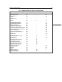 166
166
-
 167
167
-
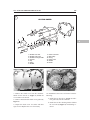 168
168
-
 169
169
-
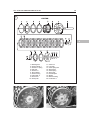 170
170
-
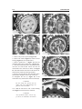 171
171
-
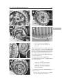 172
172
-
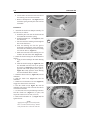 173
173
-
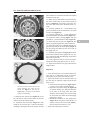 174
174
-
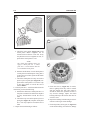 175
175
-
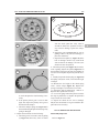 176
176
-
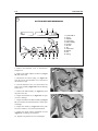 177
177
-
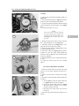 178
178
-
 179
179
-
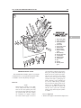 180
180
-
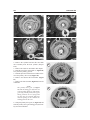 181
181
-
 182
182
-
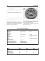 183
183
-
 184
184
-
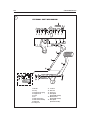 185
185
-
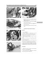 186
186
-
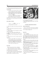 187
187
-
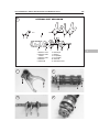 188
188
-
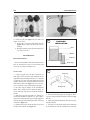 189
189
-
 190
190
-
 191
191
-
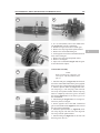 192
192
-
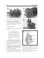 193
193
-
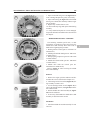 194
194
-
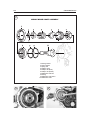 195
195
-
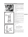 196
196
-
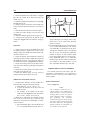 197
197
-
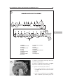 198
198
-
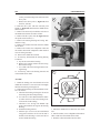 199
199
-
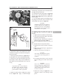 200
200
-
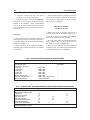 201
201
-
 202
202
-
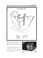 203
203
-
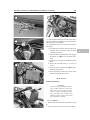 204
204
-
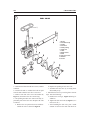 205
205
-
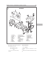 206
206
-
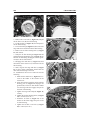 207
207
-
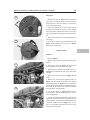 208
208
-
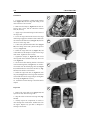 209
209
-
 210
210
-
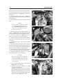 211
211
-
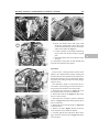 212
212
-
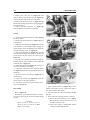 213
213
-
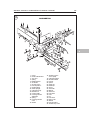 214
214
-
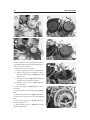 215
215
-
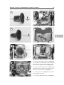 216
216
-
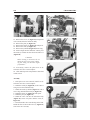 217
217
-
 218
218
-
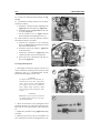 219
219
-
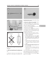 220
220
-
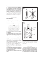 221
221
-
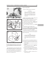 222
222
-
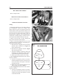 223
223
-
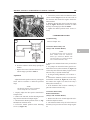 224
224
-
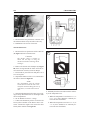 225
225
-
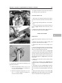 226
226
-
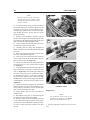 227
227
-
 228
228
-
 229
229
-
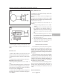 230
230
-
 231
231
-
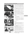 232
232
-
 233
233
-
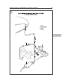 234
234
-
 235
235
-
 236
236
-
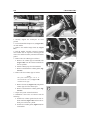 237
237
-
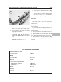 238
238
-
 239
239
-
 240
240
-
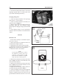 241
241
-
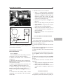 242
242
-
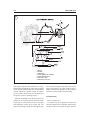 243
243
-
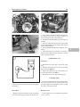 244
244
-
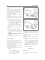 245
245
-
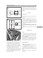 246
246
-
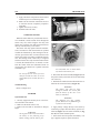 247
247
-
 248
248
-
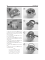 249
249
-
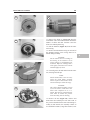 250
250
-
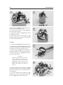 251
251
-
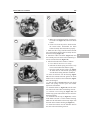 252
252
-
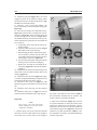 253
253
-
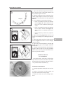 254
254
-
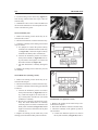 255
255
-
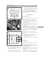 256
256
-
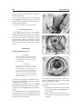 257
257
-
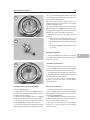 258
258
-
 259
259
-
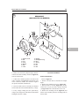 260
260
-
 261
261
-
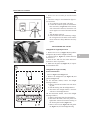 262
262
-
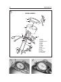 263
263
-
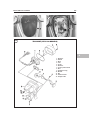 264
264
-
 265
265
-
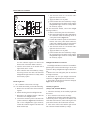 266
266
-
 267
267
-
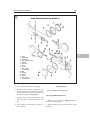 268
268
-
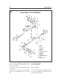 269
269
-
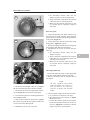 270
270
-
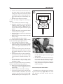 271
271
-
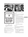 272
272
-
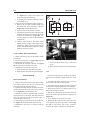 273
273
-
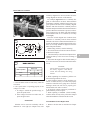 274
274
-
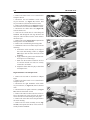 275
275
-
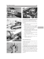 276
276
-
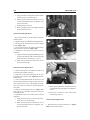 277
277
-
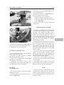 278
278
-
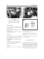 279
279
-
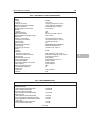 280
280
-
 281
281
-
 282
282
-
 283
283
-
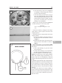 284
284
-
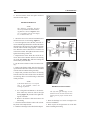 285
285
-
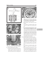 286
286
-
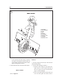 287
287
-
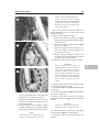 288
288
-
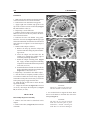 289
289
-
 290
290
-
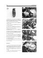 291
291
-
 292
292
-
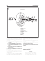 293
293
-
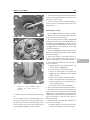 294
294
-
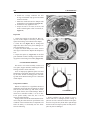 295
295
-
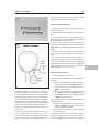 296
296
-
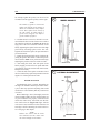 297
297
-
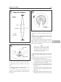 298
298
-
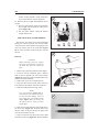 299
299
-
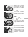 300
300
-
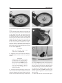 301
301
-
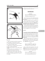 302
302
-
 303
303
-
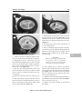 304
304
-
 305
305
-
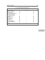 306
306
-
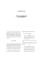 307
307
-
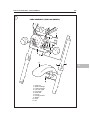 308
308
-
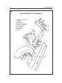 309
309
-
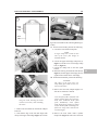 310
310
-
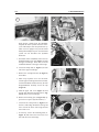 311
311
-
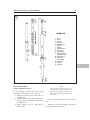 312
312
-
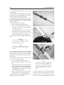 313
313
-
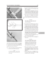 314
314
-
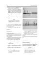 315
315
-
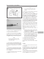 316
316
-
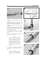 317
317
-
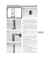 318
318
-
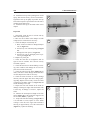 319
319
-
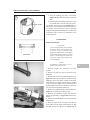 320
320
-
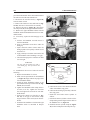 321
321
-
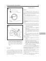 322
322
-
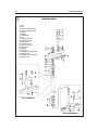 323
323
-
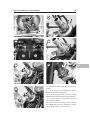 324
324
-
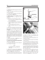 325
325
-
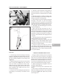 326
326
-
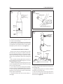 327
327
-
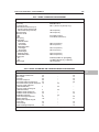 328
328
-
 329
329
-
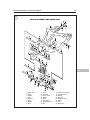 330
330
-
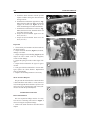 331
331
-
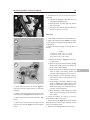 332
332
-
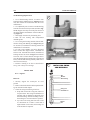 333
333
-
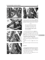 334
334
-
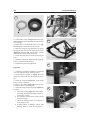 335
335
-
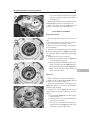 336
336
-
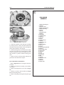 337
337
-
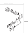 338
338
-
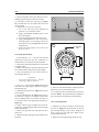 339
339
-
 340
340
-
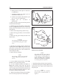 341
341
-
 342
342
-
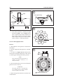 343
343
-
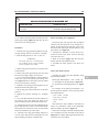 344
344
-
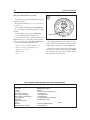 345
345
-
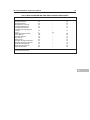 346
346
-
 347
347
-
 348
348
-
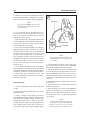 349
349
-
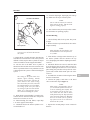 350
350
-
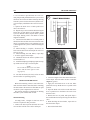 351
351
-
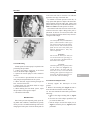 352
352
-
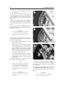 353
353
-
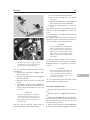 354
354
-
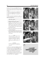 355
355
-
 356
356
-
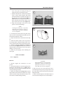 357
357
-
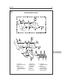 358
358
-
 359
359
-
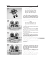 360
360
-
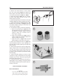 361
361
-
 362
362
-
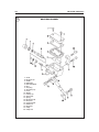 363
363
-
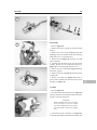 364
364
-
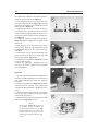 365
365
-
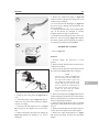 366
366
-
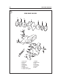 367
367
-
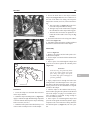 368
368
-
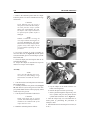 369
369
-
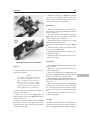 370
370
-
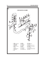 371
371
-
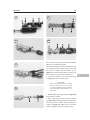 372
372
-
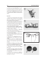 373
373
-
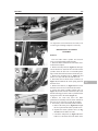 374
374
-
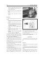 375
375
-
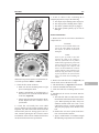 376
376
-
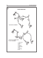 377
377
-
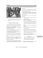 378
378
-
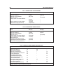 379
379
-
 380
380
-
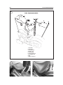 381
381
-
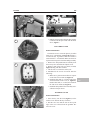 382
382
-
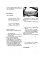 383
383
-
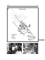 384
384
-
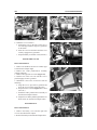 385
385
-
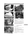 386
386
-
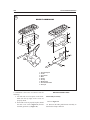 387
387
-
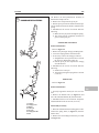 388
388
-
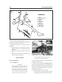 389
389
-
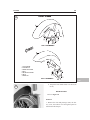 390
390
-
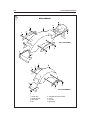 391
391
-
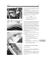 392
392
-
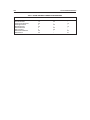 393
393
-
 394
394
-
 395
395
-
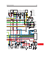 396
396
-
 397
397
-
 398
398
-
 399
399
-
 400
400
-
 401
401
-
 402
402
-
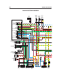 403
403
-
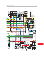 404
404
-
 405
405
-
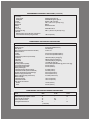 406
406
-
 407
407


Yamaha DragStar XVS1100 Owner's manual
- Category
- Toy vehicles
- Type
- Owner's manual
- This manual is also suitable for
Ask a question and I''ll find the answer in the document
Finding information in a document is now easier with AI
Related papers
-
Yamaha Time Clock XJR1300 (L) '99 User manual
-
-
-
-
-
-
-
-
-
Other documents
-
Generation Lighting OL5901BK Installation guide
-
 LT Sport 769553135125 for Toyota 14" (R14) Rim Skin Hubcap ABS 4pcs Wheel Cover User guide
-
 Ottomanson CT600 Installation guide
-
 OK LIGHTING OK-5119S Installation guide
-
Ralph Lauren RL 1320 Installation guide
-
Vestil HT-10-2036A Owner's manual
-
 Baja Designs S2 Pro Installation guide
-
 Walker Edison Furniture Company HD40MSTBL Installation guide
-
Husky H4425 Operating instructions
-
Bontrager Universal Fender Set Assembly Manual


