Boss Audio Systems BV7260B-V2 Owner's manual
- Category
- Car media receivers
- Type
- Owner's manual


CONTENTS
Safety Precautions................................................................2-3
Installation.................................................................4-6
Wiring Connections...................................................................7
Basic Operation......................................................................8
Radio Operation...............................................................9-10
USB/SD Operation.................................................................11
Bluetooth Operation...........................................................12-13
Other Operations.................................................................14
Maintenance................................................................15
IR Remote Control..............................................................16
Simple Troubleshooting Guide...............................................17
Specifications...........................................................18

2
SAFETY PRECAUTIONS
Important Warnings to Take Note of BEFORE
Commencing Installation
Damage Caused By Incorrect Installation or Usage is
NOT Covered By Warranty.
PLEASE Take the Time to Read the Installation Notes
Carefully.
To Validate the Warranty Please Ensure That the Unit is
Installed by a Professional, VAT registered Car Audio
Installation Company.
To avoid short in your vehicles electrical system, be sure to disconnect
the battery cable before beginning installation.
The unit is intended for vehicles with a 12-volt battery and negative grounding.
Before installing the unit in a recreational vehicle, truck, or bus, check that the
battery voltage is 12 volts.
Remove the two transport screws from the top of the unit before instal-
lation.
Be sure to connect the negative (-) speaker leads to the negative (-) speaker
terminal. Never connect the negative (-) speaker leads to chassis ground.
This unit is only designed for use with 4 speakers. Do not combine outputs
for use with 2 speakers. Do not ground negative speaker leads to the chassis
ground.
Speakers connected to this unit must be high-power units with a minimum
rating of 45W and impedance of 4 to 8 ohms. Connecting speakers with output
and/or impedance values other than those noted there will result in damage to
the head unit and the speakers.
Check the condition off your speakers carefully - connecting the unit to
old of degraded speakers may result in a fault which will damage the
audio IC and invalidate the warranty.
If this unit is installed in a vehicle that does not have an ACC (accessory)
position on the ignition switch, the red lead of the unit should be connected to
a terminal coupled with ignition switch ON/OFF operations. If this is not done,
the vehicle battery may be drained when you are away from the vehicle for
several hours.

3
Secure the wiring with cable clamps or adhesive tape. To protect the wiring,
wrap adhesive tape around them where they lie against metal parts. To avoid
short-circuiting, cover all disconnected lead with insulating tape. There is a
possibility of short-circuiting if the leads are not insulated.
Route and secure all wiring so it cannot touch any moving parts, such as the
gear lever and handbrake. Do not route wiring in places that get hot, such as
near the heater outlet. If the insulation of the wiring melts or gets torn, there is
a danger of the wiring short circuiting to the vehicle’s body.
Don’t pass the yellow lead through a hole into the engine compartment to
connect to the battery. This will damage the lead’s insulation and cause a very
dangerous short.
Do not shorten any leads, if you do, the protection circuit may fail to work
when it should.
Never feed power to other equipment by cutting the insulation of the power
supply lead of the unit and tapping into the lead. The current capacity of the
lead will be exceeded, causing overheating.
Since a unique audio I/C circuit is employed, never wire so the speaker leads
are directly grounded or the left and right - speaker leads are common.
When this product’s source is switched ON, a control signal is outputted
through the orange lead. Connect to an external power amp’s system remote
control or the car’s Auto-antenna relay control terminal (max. 300mA 12V DC).
If the car features a glass antenna, connect to the antenna booster power
supply terminal.
When an external power amp is being used with this system, do not connect
the orange lead to the amp’s power terminal. Such connection could cause
excessive current drain and a major malfunction. Refer to the relevant owner’s
manual for details on connecting the power amp and other units, then make
the connections correctly.
Do not block any vents or heater panels, Blocking them will cause heat to build
up and may result in fire.
If noise is still experienced when the motor of the vehicle accelerates, a choke
should be placed in line with the power to the unit. The installation company
will know what is required.
When replacing the fuse(s) the replacement must be of the same amperage
as shown on the fuse holder. Never replace a fuse with another of a different
value. If the fuse blows again please contact your instsallation company.
Double check that all wiring and connections are correct before re-connecting
the battery and turning on the unit.
After completing the installation and before operating the unit, reconnect the
battery, then press the (RES) button with a pointed object, such as a ball-point
pen to set to unit to it’s initial status. After pushing the button, wait a few sec-
onds for the red light to flash.
SAFETY PRECAUTIONS

4
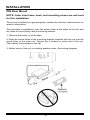
Remove the Old Unit from the Dashboard
DIN Front Mount
DO NOT DISCONNECT WIRES
AT THIS TIME!
2. Insert the keys supplied with the
old unit into both sides of the unit
as shown in figure below until
they click. Pull to remove the old
unit from the dashboard.
1. Remove the outer trim frame.
INSTALLATION
Tools for Installation
2 removal wrenches are supplied for taking out the old unit and place with this
brand name car radio. The following tools and supplies may also be needed for
the installation:
Tools for Installation: Philips Screw-drivers /Machine Screws /Wire Stripper
/Wire Cutter /Hammer /Pencil /Electrical Tape /Electric Drill
Supplies for Installation: Machine Screws /Crimp Connectors /14 Gauge Wire for
Power Connections /14-16 Gauge Speaker Wires
The above are not supplied.
Before you install
Automotive audio equipment installations can be challenging even to the most
experienced of installation technicians. We strongly recommend that this unit
should be professionally installed by a VAT registered installer (this is a require-
ment to validate the warranty).
IMPORTANT: Remove the two transport screws from the top fo the unit before
installing.
Mark Polarity of the Speaker Wires
Marking the polarity of the speaker wirers will make it easier to connect the
existing speakers to your car radio. Consult wiring diagram of existing head unit
before disconnecting any wires. If you are not positive of the polarity of the exist-
ing wires from the speakers to the head unit, install new wires.
1. While the old unit is playing, disconnect the wires from one speaker.
2. Take a length of masking tape and fold it around the wire so it forms a flag.
3. On the masking tape mark the polarity of the speaker wires (+&-), as well as
left or right, and front or rear.
4. Double check that you marked the first speaker correctly by checking that the
speaker wires are the same at the head unit.
5. Repeat this procedure for all of the speakers.
6. Mark the power, ground, and any other wires also.

5
1. After removing the old radio
and mounting sleeve, insert sup-
plied mounting sleeve into open-
ing.
2. Bend the tabs on the mount-
ing sleeve to keep the mount-
ing sleeve firmly in place.
3. Attach wires from the unit to
existing wires. See wiring con-
nections diagram. Insert radio
into dashboard. Then apply the
trim frame to outside of radio.
4. Support radio using rear mounting
bolt and steel bar. (not included)
DIN Front Mount
INSTALLATION
WARNING!
Disconnect negative battery terminal from battery before start-
ing installation. Consult the vehicle’s owner’s manual for proper
instructions.
NOTE: Mark the polarity of the existing speaker wires before discon-
necting battery.
NOTE: Remove the two transport screws from the top of the unit
before installing.

6
NOTE: Outer trim frame, hook, and mounting sleeve are not used
for this installation
This is only intended as a general guide; contact the vehicle’s manufacturer for
specific instructions.
This menthod of installation uses the screw holes at the sides of the unit and
the holes of the existing vehicle mounting bracket.
1. Remove the hooks on both sides.
2. Aligh the screw holes of the mounting bracket supplied with the car and the
screw holes of the main unit. Tighten the 2 screws on each side of the unit.
Then fasten the brackets to the car.
3. Attach wires of the unit to existing speaker wires. See wiring diagram.
DIN Rear Mount
INSTALLATION

7
WIRING CONNECTIONS
Make sure You have a good chassis ground. Good ground connection will
eliminate most electrical noise problems. A good chassis ground requires a
tight connection to the vehicle’s metal chassis. The area around the ground
connection should be clean, bare metal without rust, paint, plastic, dust, or dirt
for a good ground connection.
Black Ground
Connect to vehicle body/chassis. Make sure you have a good chassis ground.
This will eliminate most electrical noise form the motor and alternator. A good
chassis ground requires a tight connection to ground. The area should be free
from rust, paint or any form of dirt.
Yellow Memory Backup
Connect to electrical terminal always supplied with power regardless of ignition
switch position.
Orange Remote
Connect to Auto-antenna or power amp control wire/remote connection.
Maximum current 300mA 12VDC. (Low Current)
Parking wire connection
Speaker Wiring Notes:
Follow the above wiring diagram to install the head unit with new or existing
speakers.
1. This unit is designed for use with four (4) speakers with impedance between
4 Ohms to 8 Ohms.
2. An Impedance load of less than 4 Ohms could damage the unit.
3. Never bridge or combine the speaker wire outputs. When not using four
speakers, use electrical tape to tape the ends of the unused speaker outputs to
prevent a short circuit.
4. Never ground the negative speaker terminals to chassis ground.
RCA Line out
(Left=White;Right=Red)
Parking wire(green)
Video output(yellow)
ISO Connector
Fuse 10A
Antenna Socket
Connector A
1. Rear right speaker(+)/Purple
2.
3. Front right speaker(+)/Grey
5. Front left speaker(+)/White
Rear right speaker(-)/Purple-Black
4. Front right speaker(-)/Grey-Black
6. Front left speaker(-)/White-Black
7. Rear left speaker(+)/Green
8. Rear left speaker(-)/Green-Black
Connector B
1. -
2. -
3. -
4. Battery 12V (+)/Yellow
5. Remote Trlgger/Blue-white
6. -
7. ACC+/Red
8. Ground/Black
If parking cable is connected to hand brake switch, the video display of the mon-
itor will be controlled by driving status, system setup and input video sources.
When the car is moving ahead, if the video is played, the screen shows warning.
The warning screen will prevent the driver from watching images.
Parking brake
lead
Brake light
Car frame
Battery
Purple Wire

8
Basic Operation
1. Turning the unit On / Off
Press the Power Button to turn the unit on. When the unit is on, press the Power Button
once to turn the TFT off. During TFT off, the video out signal will be available so that the
connected monitor will show the screen of the unit. Press the Power Button again to turn the
TFT back on. Press and hold the POW button again to turn the unit off.
2. Mode Selection
Press the volume knob Button to cycle the Play Mode between RADIO, USB, SD, BT and
AUX in.
3. Sound Control
A. Volume
Use the VOL +/- Button to adjust the volume level. Turn the button clockwise to increase the
volume, and vice versa. The larger the number of volume, the higher the volume level.
B. Bass
Press the SEL Button until the display shows “BAS”. Use the VOL +/- Button to adjust. When
EQ is ON, bass control is not available.
C. Treble
Press SEL Button until the display shows “TRE”. Use the VOL +/- Button to adjust. When EQ
is ON, treble control is not available.
D. Balance
Press SEL Button until the display shows “BAL”, then use the VOL +/- Button to adjust the
balance between the left & right speakers.
E. Fader
Press SEL Button until the display shows “FAD”, then use the VOL +/- Button to adjust the
balance between the front & rear speakers.
F. Preset Equaliser Function
Press the SEL Button until the display shows “EQ OFF”, then use the VOL +/- Button to
choose the equaliser sound effects. The Sequence of equaliser setting will be EQ OFF-
POP-ROCK-CLASSIC.
G. Beep On/off
Press the SEL Button until the display shows “BEEP ON”, then use the VOL +/- Button to
turn the beep sound off. The word “BEEP OFF” will be shown on the display.
H. Loudness
Press SEL Button until the display shows “LOUD OFF”, then use the VOL +/- Button to turn
loudness on. The word “LOUD ON” will be shown on the display.
4. Mute Control
Press the MUT Button to activate the Mute function. Press MUT Button again or use the
VOL +/ - Button to cancel.
5. HOME Button
In Radio and Aux modes, press the HOME button to go back to the home screen. You can
select different play modes by turning and pressing the volume knob. Also you can enter the
setup menu in the home screen.
In USB and SD modes, during music or video playback, press the HOME button once to go
back to the directory page, in which you can choose the desired file by pressing and turning
the volume knob. Press again the HOME button to go back to the home screen.
6. SETUP
Enter the setup menu in the home screen by turning and pressing the volume knob. Turn
the volume knob to each item you would like to set. Press the volume knob in each of the
item, followed by turning the volume knob to adjust settings. After adjusting, press the vol-
ume knob to confirm. Repeat these steps to finish the setting of other items. You can adjust
language, date, time, brightness and master reset accordingly.
7. Clock
Press the clock button on the remote control to see the time during USB and SD modes. The
clock always shows itself during radio and Aux modes.

9
Radio Operation
1. Choose Radio Band
Press the MOD Button to access the radio function. Then press the BND button
to choose among the five radio bands - three FM Bands (FM1, FM2, and FM3)
and two AM Bands (AM1, and AM2). Each of the five bands can store up to six
preset stations, for a total of 30 preset memory stations.
2. Radio Tune/Seek Function
In radio mode, press the Seek +/- button to automatically seek the next strong
and clear radio station. Press and hold the Seek +/- button until the screen
shows MANU SEEK. At this time, you can manually fine tune your desired
frequency. Wait until the MANU SEEK to disappear in order to perform auto
seek again.
3. Automatic Store/Preset Scan
A. Automatic Scan & Store
While listening to the FM Radio, press and hold the APS Button for 3 seconds.
The receiver will automatically scan and save stations for all the 3 FM Bands,
whichever band (FM1, 2 or 3) you are listening to.
While listening to the AM Radio, press and the APS Button for 3 seconds. The
receiver will automatically scan and save stations for the 2 AM Bands, which-
ever band (AM1 or 2) you are listening to.
B. Scan Saved Stations
Press the APS button or the AMS button on the remote control once to perform
the scanning functions. In FM mode, press the APS button or the AMS button
and the stations in that FM band will be scanned; press the button in AM mode
and scan the band stations of that AM Band.
4. LIST button
In radio mode, press the LIST button to go to the preset stations list. Press again
to go to the function list. You can select or change setting in the lists by turning
and pressing the volume knob.
In USB/SD mode, press the LIST button during audio playback in order to enter
the song list. Choose the desired song by turning and pressing the volume knob.
Press the LIST button again to leave the song list.
5. Save your Preset Stations
After choosing the preset stations in the list, you can adjust the frequency (by
Seek +/-). There are six numbered preset buttons which can store and recall
stations for each band. While listening to a radio station you would like to save
as a preset,press and hold one of the buttons numbered 1-6 until you hear a
beep. The button you pressed is now the preset button for that station. You can
find the same buttons numbered 1-6 with the same function on the remote .
6. Mono/Stereo Reception Control
After choosing ST in the list, you can turn ST on or off to select stereo or mono
reception. Improvement of reception of weak stations can be done by selecting
ST OFF operation which may cut down some reception noise.
7. Local/Distance Reception Control
After choosing LOC in the list, you can turn LOC on or off to select local or
distance reception. Improvement of reception of distant stations can be done by
selecting LOC OFF operation.

10
Radio Operation (Con’d)
8. Switchable Frequency
The default radio frequency of this product is for U.S. However, you can
set different frequency modes if you are using this product outside U.S.
Press the HOME button and rotate the volume knob to select SETUP.
Enter the SETUP menu and select RADIO AREA and confirm by holding
the SEL knob.
Select your desired radio frequencies as follows:
a. America1 (for U.S.) – FM 87.5-107.9MHz, AM 530-1710KHz.
b. America2 (for South America) – FM 87.5-108MHz, AM 530-1710KHz.
c. Japan (for Japan) – FM 76-90MHz, AM 522-1629KHz.
d. Russia (for Russia) – FM 65-108MHz, AM 522-1620KHz.
e. Europe (for European and Asia) – FM 87.5-108MHz, AM 522-1620KHz.

11
USB/SD Operation
Plug the USB/SD card into the USB/SD port. The unit will play the contents
automatically.
1. Advance / Go Back
Advance to the next track or go back to the previous track by pressing the for-
ward or rewind buttons. Press and hold the same button for fast forward/rewind
the song/video, you may stop anytime by pressing the play/pause button.
2. Play/Pause
Press the play/pause button to pause the playback or resume.
3. TYPE button
Switch the current playback (eg. Music) to another type (eg. Video) by pressing
the TYPE button. The type switch will depend upon the contents in the USB/SD
device.
4. HOME button
Press the HOME button during playback in order to see the full list of files. All
the file names are displayed for your easy reference. Select the desired files by
turning and pressing the volume control.
5. Aspect Ratio
During video playback, press and hold the volume control in order to switch the
aspect ratio of the video. You can select full screen, 16:9, and 4:3 accordingly.
The viewing effect will depend on the video file so it may vary.

12
Bluetooth Wireless Device Operation
Pairing Your Mobile Phone
Before using Bluetooth functions, you must pair your mobile phone and the unit.
Pairing is a special process used when two devices connect for the first time.
The pairing process is used to generate a link key that is used for authentication
purposes for future Bluetooth connections between devices. Your mobile phone
can initiate a search for a new device and pair the unit.
1. Access the mobile phone’s Bluetooth function and set the Bluetooth function
to on
2. Use the mobile phone’s add a new device feature. “BOSS AUDIO” appears
in the list on your mobile phone.
3. Select “BOSS AUDIO”. The unit has an auto pairing function. It will search for
the Bluetooth mobile phone and pair automatically. A prompt to connect should
appear on your mobile phone. Accept the request and initiate the process
NOTE: Some mobile phones require a “pass key” or pairing code to connect.
If your phone requires a pass key or pairing code, you will need to enter this
number. The default pairing code for the unit is “0000”.
Plug the USB/SD card into the USB/SD port. The unit will play the contents
automatically.
Auto-Reconnection
This unit has a built-in auto-reconnection function. In some conditions, the unit
will auto reconnect with the mobile phone (note: the mobile phone must have
been paired with the unit before.)
• When you turn off the unit and then turn it on again.
• Switch off the ACC wire and switch it on again.
Managing Incoming Calls
Answering an Incoming Call
Press the GREEN button to answer an incoming call.
Rejecting an Incoming Call
Press the RED button to reject the incoming call.

13
Bluetooth Wireless Technology Music Function
Wireless products featuring Bluetooth technology provides an Advanced Audio
Distribution Profile (A2DP) profile for streaming music from a mobile phone or a
portable multimedia player (PMP), sometimes referred to as a MP3 player. The
unit allows you to play back audio files from your mobile phone or a PMP using
a Bluetooth connection.
Note: Your mobile phone must support this function. Please refer to your
mobile phone’s instruction manual.
When in A2DP mode
Press the PREVIOUS button on the front panel of the unit to choose the previ-
ous track.
Press the NEXT button on the front panel of the unit to choose the next track.
Press the APS/PAUSE button on the panel control to pause play.
Bluetooth Wireless Device Operation

14
Other Operations
1. AUX Input
The AUX Input Jack is a 3.5mm stereo jack on the front panel of the unit. Press
the Mode button to choose AUX. Connect any portable audio device such as a
MP3 player to unit. Use the volume control to adjust volume.
2. RCA Output
The RCA Output Jack is on the back of the unit. (Refer to Wiring Diagram)
This output is for connecting amplifier, equaliser, or other audio component that
requires a pre-amp out connection. (Red=Right, White=Left) Follow the manu-
factures instructions for the audio component that you are connecting.
3. Video Output
The video output Jack is on the back of the unit. (Refer to Wiring Diagram)
When the unit is on, press POW/TFT OFF button on the panel to switch off the
display. When the display is off, the video out signal will be available so that the
connected monitor will show the screen of the unit. Press this button again to
resume the image.

15
Maintenance
Cleaning the Unit
Do not use any liquids to clean this unit.
Do not use petroleum distillates to clean this unit.
Use a clean, dry cloth to clean this unit.
Replacing the Fuse
Make sure the amperage matches the specified value when replacing the
fuse(s). If the fuse is bad, check the power connection and replace the fuse
with a new one. If the same problem occurs, this might indicate a malfunction
within the unit.
Warning
When replacing a fuse, do not use a fuse with a higher am-
perage rating than the fuse originally supplied to your unit,
otherwise damage will result to your unit.

16
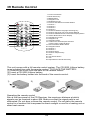
IR Remote Control
Operating the remote control
Aim at the face panel of the CD Receiver, the maximum distance at which
signals can be received is about 6M. Make sure that the signal path is not
obstructed. Do not drop or throw the remote control. Do not place the remote
control in a location that is exposed to direct sunlight or next to a heating unit or
other heat source.
This unit comes with a full remote control system. The CR-2025 Lithium battery
is an included item with the remote control. TO PLACE THE BATTERY:
(1) Remove the cover from the back of the remote control.
(2) Insert a CR-2025 Lithium battery.
(3) Insert the battery holder into the back of the remote control.
1) 2) 3)
1
1. Power On/off/mute
2. Mode Select Key
3. MENU Button
4. Navigation Left
5. Band/Select Type
6. Previous Track/Previous Radio Station
7. Number 1
8. Number 2
9. Number 5
10. Number 6
11. Number 9/Subtitle Language Switching Key
12. Number 0/Change The Audio Output Method
13. Number #/Statistical Disc Information Display Button
14. Answer Button/Time Clock Display
15. Play/Pause Function
16. Navigation Up
17. Navigation Right
18. Confirm The Track/Chapter Selected
or Select Item In SETUP Menu.
19. Next Track/Next Radio Station
20. Navigation Down
21. Number 4
22. Number 3
23. Number 8/Intro
24. Number 7/Repeat Play
25. VOL+
26. Auto Preset Scan/*
27. VOL-
28. Reject Button /Sound Select Key
2
3
4
5
15
16
17
18
19
20
21
22
23
24
25
26
27
28
6
7
8
9
10
11
12
13
14

17
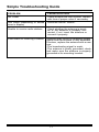
Simple Troubleshooting Guide
PROBLEM
No Power
Unit stops responding or shows
error in display
Unable to receive radio stations
Poor effect on receiving a station
CAUSE/SOLUTION
Check whether the fuse is blown, replace
with fuse of proper value if necessary.
Press the RESET Button .
Check whether the antenna is insert-
ed or the antenna is properly con-
nected; if not, insert the antenna or
connect it properly.
-Antenna may not be of the proper length.
Make sure the antenna is fully extended.
If broken, replace the antenna with a new
one.
-The broadcasting signal is weak.
-The antenna is poorly grounded; check
and make sure the antenna is properly
grounded at its mounting location.

18
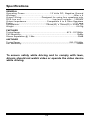
Specifications
GENERAL
Operating Power.....................................12 Volts DC, Negative Ground
Wattage............................................................................80w x 4
Output Wiring.............................Designed for using four speakers only
RCA line out............................................low-level outputs - 1000MV
Output Impedance..............................Compatible 4 to 8 Ohm Speakers
Fuses...........................................................................................10 amp
Dimensions.......................................178mm(W) x 78mm(D) x 51mm (H)
Weight..................................................................................................0.8 Kg
FM/TUNER
Tuning Range...............................................................................87.5 - 107.9MHz
FM Sensitivity..........................................................................................12dBu
Stereo Separation @ 1 Khz.....................................................................35dB
AM/TUNER
Tuning Range...................................................................................530-1710 KHz
Am Sensitivity....................................................................................30dBu
To ensure safety while driving and to comply with laws,
drivers should not watch video or operate the video device
while driving.

-
 1
1
-
 2
2
-
 3
3
-
 4
4
-
 5
5
-
 6
6
-
 7
7
-
 8
8
-
 9
9
-
 10
10
-
 11
11
-
 12
12
-
 13
13
-
 14
14
-
 15
15
-
 16
16
-
 17
17
-
 18
18
-
 19
19
-
 20
20


Boss Audio Systems BV7260B-V2 Owner's manual
- Category
- Car media receivers
- Type
- Owner's manual
Ask a question and I''ll find the answer in the document
Finding information in a document is now easier with AI
Related papers
-
 Boss Audio Systems BV7260B Owner's manual
-
 Boss Audio Systems BV7254 User manual
-
 Boss Audio Systems BV7332B User manual
-
Boss Audio Systems BV7335B Owner's manual
-
-
 Boss Audio Systems 746UAB Owner's manual
-
 Boss Audio Systems BV7254 Owner's manual
-
 Boss Audio Systems 824UAB Owner's manual
-
 Boss Audio Systems BV7280 User manual
-
 Boss Audio Systems BVI9997B Owner's manual


Other documents
-
 Planet Aaudio P395UAB User manual
-
Hyundai H-CMD7079 User manual
-
-
-
 Lightning Audio LA-2300BT Owner's manual
-
Pyle PL78DLB User manual
-
Planet Aaudio P390UAB User manual
-
Caliber RDD571BT Owner's manual
-
-

