Page is loading ...

11921 Slauson Avenue.
Santa Fe Springs, CA. 90670
(800) 227-4116
INSTALLATION
MANUAL
© MAXON Lift Corp. 2008
RC-2B
RC-3B
RC-4B
RC-5B
RC-6B
RC-6K
M-90-01
REV. D
JULY 2008

2
11921 Slauson Ave. Santa Fe Springs, CA. 90670 (800) 227-4116 FAX (888) 771-7713
TABLE OF CONTENTS
WARNINGS ........................................................................................................................... 3
SAFETY INSTRUCTIONS .................................................................................................... 3
INTRODUCTION ...................................................................................................................4
UNIT AS SHIPPED ................................................................................................................5
INSTALLATION OF UNIT ...................................................................................................... 6
WELDING TO FLATBED ......................................................................................................11
HYDRAULIC PIPE INSTALLATION .................................................................................... 12
POWER PACK INSTALLATION .......................................................................................... 13
FUSED POWER CABLE ..................................................................................................... 16
PUMP WIRING CAM CLOSER ........................................................................................... 17
PUMP WIRING HYDRAULIC CLOSER .............................................................................. 18
ADD HYDRAULIC FLUID .................................................................................................... 19
FINAL ADJUSTMENTS ....................................................................................................... 21
ATTACH DECALS ............................................................................................................... 23
OPTIONS ............................................................................................................................ 25
RCT LIGHT INSTALLATION ................................................................................................ 25
RCT LIGHT INSTALLATION - Continued ............................................................................ 26
HAND PUMP OPTION FOR CAM CLOSER ....................................................................... 27
BATTERY PAK INSTALLATION (For Trailers) ..................................................................... 28
RECOMMENDED LIFTGATE POWER CONFIGURATION ................................................ 29
BATTERY CABLE MOUNTING, 6 VOLT SYSTEM ............................................................. 31
BATTERY CABLE MOUNTING, 12 VOLT SYSTEM ........................................................... 32
FIXED RAMP INSTALLATION, 6” ....................................................................................... 33
FIXED RAMP INSTALLATION, 12” ..................................................................................... 34
CART STOP & DUAL CART STOP RAMP INSTALLATION ................................................ 35
HINGED RAMP INSTALLATION (STEEL) .......................................................................... 36
HINGED RAMP INSTALLATION (ALUMINUM) ................................................................... 37

3
11921 Slauson Ave. Santa Fe Springs, CA. 90670 (800) 227-4116 FAX (888) 771-7713
SAFETY INSTRUCTIONS
WARNINGS
SAFETY INSTRUCTIONS
• Comply with all WARNING and instruction decals attached to the Liftgate.
• Keep decals clean and legible. If decals are illegible or missing, replace them. Free replacement
decals are available from Maxon Customer Service.
• Consider the safety and location of bystanders and location of nearby objects when operating the
Liftgate. Stand to one side of the platform while operating the Liftgate
• Do not stand, or allow obstructions, under the platform when lowering the Liftgate. Be sure your
feet are clear of the Liftgate.
• Keep fi ngers, hands, arms, legs, and feet clear of moving Liftgate parts (and platform
edges) when operating the Liftgate.
• Wear appropriate safety equipment such as protective eyeglasses, faceshield and clothing while
performing maintenance on the Liftgate and handling the battery. Debris from drilling and contact
with battery acid may injure unprotected eyes and skin.
• Make sure vehicle battery power is disconnected while installing Liftgate. Connect vehicle
battery power to the Liftgate only when installation is complete or as required in the installation
instructions.
• Do not allow untrained persons to operate the Liftgate.
• Be careful working by an automotive type battery. Make sure the work area is well ventilated and
there are no fl ames or sparks near the battery. Never lay objects on the battery that can short the
terminals together. If battery acid gets in your eyes, immediately seek fi rst aid. If acid gets on your
skin, immediately wash it off with soap and water.
• If an emergency situation arises (vehicle or Liftgate) while operating the Liftgate, release the con-
trol switch to stop the Liftgate.
Comply with the following WARNINGS and SAFETY INSTRUCTIONS while installing
Liftgates. See Operation Manual for operating safety requirements.
• Read and understand the instructions in this Installation Manual before installing Liftgate.
• Before operating the Liftgate, read and understand the operating instructions in Operation
Manual.
• A correctly installed Liftgate operates smoothly and reasonably quiet. The only noticeable noise
during operation comes from the power unit while the platform is raised and lowered. Listen for
scraping, grating and binding noises and correct the problem before continuing to operate Liftgate.
• If it is necessary to stand on the platform while operating the Liftgate, keep your feet and any
objects clear of the inboard edge of the platform. Your feet or objects on the platform can become
trapped between the platform and the Liftgate extension plate.
• Never perform unauthorized modifi cations on the Liftgate. Modifi cations may result in early failure
of the Liftgate and may create hazards for Liftgate operators and maintainers.
• Correctly stow platform when not in use. Extended platforms could create a hazard for
people and vehicles passing by.
WARNING
• Recommended practices for welding on steel parts are contained in the current AWS (American
Welding Society) D1.1 Structural Welding Code - Steel. Damage to Liftgate and/or vehicle, and
personal injury can result from welds that are done incorrectly.
!
WARNINGS

4
11921 Slauson Ave. Santa Fe Springs, CA. 90670 (800) 227-4116 FAX (888) 771-7713
INTRODUCTION
This publication contains the information required to install the following
models and their options; RC, RCW, RCT, RC-CL, and RCHL from 2000
to 6000 pound capacities. If there is any doubt in your mind regarding the
suitability of these lifts being installed on its intended vehicle, or any portion
of these instructions that you do not understand, please contact the Maxon
Customer Service Department for consultation.
Unauthorized modifi cation to this equipment may cause premature
failure or create hazards in its use that are not foreseen at the time of the
installation. These kinds of changes should be discussed with our Engineering
Department before being undertaken.
Bed height requirements to ground are 38” laden to 56” unladen.
These lifts cannot be installed on bodies with swing type doors.
These lifts have been designed to fi t bodies that are 96” wide, (102”
wide, in the case of the RCW Models). If this body has dimensions that are
much different than these, special brackets will have to be fabricated for
attachment. The corner posts of the body must also be made of steel so that
the lift columns can be welded to it. If they are aluminum, then steel plates
will have to be fabricated to bolt to these corner posts for welding to the lift
assembly. Both of the above conditions are rare and therefore have not been
provided for in this manual. Contact the Customer Service Department if either
of the above conditions exist.

5
11921 Slauson Ave. Santa Fe Springs, CA. 90670 (800) 227-4116 FAX (888) 771-7713
UNIT AS SHIPPED
Do not remove stands at bottom of column until instructed to do so.
Steel box containing pump assembly, also contains a packing
list, instruction manuals, decals, and all necessary hardware
to complete installation.
COLUMN SUPPORT ANGLES 48”
POWER UNIT BOX
REINFORCEMENT ANGLE 8”
Two of these 18” angle iron pieces are
to be used fi rst to assist in mounting
the lift to the truck, and then to support
the pump box on trailer installations.
The other two are welded to the column
support angles.
STAND
BATTERY
PAK OPTION
PUMP BOX
STAND

6
11921 Slauson Ave. Santa Fe Springs, CA. 90670 (800) 227-4116 FAX (888) 771-7713
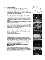
INSTALLATION OF UNIT
There are two pieces of angle iron supports (2-1/2 x 2-1/2 x
18”) that have been provided to assist in lining the unit up to the
body. Tack weld them to the top of the lifts main section, just
strong enough to support it on the truck fl oor till the lift is secured
and ready to weld. Put a chalk mark on the center of the unit (on
the thread plate surface) for aligning with the center of the truck
body.
Remove support angles after lift is mounted and use them for
pump box mount reinforcement.
SUPPORT ANGLE
SUPPORT ANGLE

7
11921 Slauson Ave. Santa Fe Springs, CA. 90670 (800) 227-4116 FAX (888) 771-7713
Corner posts and sill under rear of fl oor must be clean and free of any
obstructions so that the columns of the rail lift can fi t fl at against the rear of the
body.
Chalk mark a center line at the edge of the rear of the truck fl oor to line up
with the mark on the liftgate.
Using the lifting straps, the unit can now be raised either with a chain hoist or
fork lift to a height which will allow the temporary support angles to rest on the
body fl oor. The unit can be moved to the vehicle or the vehicle to the unit till
they meet.
INSTALLATION OF UNIT - Continued

8
11921 Slauson Ave. Santa Fe Springs, CA. 90670 (800) 227-4116 FAX (888) 771-7713
Clamp columns to the truck body and weld
as shown. Remove forklift or chain hoist.
RC-2000/3000/RC-CR3
1/4” Fillet Weld. 2” Long
RC-4000
1/4” Fillet Weld. 3” Long
RC-5000/6000
1/4” Fillet Weld. 4” Long
NOTE: See views A & B on next page.
ALL UNITS: 1/8” fi llet weld
approx. halfway
down the column.
ALL UNITS: See view C on
the next page.
INSTALLATION OF UNIT - Continued

9
11921 Slauson Ave. Santa Fe Springs, CA. 90670 (800) 227-4116 FAX (888) 771-7713
DO NOT WELD COVER
COVER
A
B
C
1/4”
1/4”
2
WELD TO CORNER
POST AND SILL
BOTTOM CORNER OF TRUCK BODY
OUTSIDE OF COLUMN ASSEMBLY
INSIDE OF COLUMN ASSEMBLY
Typ.
(Length as
specifi ed
on previous
page.)
INSTALLATION OF UNIT - Continued

10
11921 Slauson Ave. Santa Fe Springs, CA. 90670 (800) 227-4116 FAX (888) 771-7713
Cut columns off 20” from ground. Place the 2-1/2” x 18”
angle iron provided under at least 2 cross members, to
prepare for the following step and weld.
Cut one end of each of the 4 foot long angle iron braces
so that it lines up with the lift column and the other end
lays fl at against the angle iron referred to in the previous
paragraph.
20”
LIFT COLUMN
CUT
STAND
OFF
18”
ANGLE
WELD
WELD
INSTALLATION OF UNIT - Continued

11
11921 Slauson Ave. Santa Fe Springs, CA. 90670 (800) 227-4116 FAX (888) 771-7713
WELDING TO FLATBED
The column assemblies are
tied in to the fl at bed side rails
with two lengths of channel. The
required sizes are listed below.
RC-2000/3000/4000
3”-4.1 #/ft. Channel
RC-5000/6000
4”-5.4 #/ft. Channel
NOTE: Mounting Channel is not supplied by Maxon
RC-2000/3000/4000
3”of 1/4” fi llet weld
RC-5000/6000
4”of 1/4” fi llet weld
If side rail is less than 1/4” thick,
weld a 1/4” plate to side rail, then
weld channel to 1/4” plate.
RC-2000/3000/4000
3”of 1/4” fi llet weld
RC-5000/6000
4”of 1/4” fi llet weld
Weld to side rail
above a cross
member.
60”
Approx.
Cross Member

12
11921 Slauson Ave. Santa Fe Springs, CA. 90670 (800) 227-4116 FAX (888) 771-7713
HYDRAULIC PIPE INSTALLATION
Remove the seven foot long pipe that is strapped to this column of the
lift gate (two pipes if lift has hydraulic platform closer), and weld to under
side of fl oor cross members. End of pipe to be about two feet from the end of
the truck body. Connect the four foot hoses to the end of the pipe(s) closest
to the power unit and the other end through the pump box to the pump
assembly. See the last page of “Power Pak Installation” for details.
NOTE: Blow air through pipes and hoses before connections are made.
Approx. 24”

13
11921 Slauson Ave. Santa Fe Springs, CA. 90670 (800) 227-4116 FAX (888) 771-7713
POWER PACK INSTALLATION
TRUCK BODIES
TRAILER BODIES
Jack up the steel box containing the pump assembly until it touches at least
two cross members under the fl oor, three if possible, and the back of the
touches the truck chassis frame. Weld where instructed and remove jack.
Leave room for tail lights.
WELD
WELD
MAX.
Jack up the steel box containing the pump assembly until it touches
at least two cross members under the fl oor, three if possible and tack weld.
Add braces provided to the back of the box and the side of the fl oor cross
members. Weld both ends of braces and top of box. Use short pieces of angle
iron provided to weld from the side of the fl oor cross members to the front of
the box.
Make sure the box is not in a position to interfere with the wheels of the
trailer with sliding axle.
Box can also be placed behind the wheels if room permits.
20 feet
18” ANGLE
BRACE
FLOOR CROSS
MEMBERS
WELD ALL
SIDES OF
ANGLE
POWER UNIT BOX
8” (3 REQ’D,
2 SHOWN)

14
11921 Slauson Ave. Santa Fe Springs, CA. 90670 (800) 227-4116 FAX (888) 771-7713
Run 32 ft. power cable from the pump box, along the chassis frame to the
positive terminal of the battery (assuming the negative is ground). Use frame
clips to secure the cable. (Do not attach to the battery terminal until the other
end is fastened on the pump). If the cable is too long, cut to proper length.
3/8” CABLE END
TERMINAL
1/2”
SHRINK TUBE
POWER
CABLE
Strip about 1/2” of the insulation from the end and slide one of the
pieces of shrink tube far enough down that it’s out of your way. Solder the
terminal end fi rmly onto the cable.
Always wear protective eye covering while you are doing soldering
operations.
When it’s cool, slide the shrink tube over the terminal end and heat with
a heat gun til it shrinks tightly over the cable and terminal.
NOTE:
Proper cable connections are extremely important to insure a long and
effi cient life to all electrical components, therefore, solder type terminals,
solder and shrink tubing are provided to insure proper connections. Please
do not use the hammer smashing method since the constant bouncing and
vibration of the vehicle can eventually cause these types of joints to loosen
and deteriorate.
This could also be true of crimping if not done properly or the wrong size
tool is used.
POWER
CABLE
FRAME
CLIP
POWER PACK INSTALLATION - Continued

15
11921 Slauson Ave. Santa Fe Springs, CA. 90670 (800) 227-4116 FAX (888) 771-7713
Route the two hoses (3 if hydraulic closer) and the three conductor cord
(two cords if hydraulic closer), that come out of the bottom of the lift gate main
frame through the power pak box and connect as shown.
TRUCKS ONLY
TRAILERS ONLY
Connect hydraulic hose coming out of bottom of lift gate to
welded pipes under body. Tie the cord(s) and the low pressure line
to the pipe and route through power unit box.
POWER PACK INSTALLATION - Continued

16
11921 Slauson Ave. Santa Fe Springs, CA. 90670 (800) 227-4116 FAX (888) 771-7713
FUSED POWER CABLE
OPTIONAL POWER CABLE KITS
DESCRIPTION PART NUMBER FIGURE
40’ CABLE ASSEMBLY 264848
10’ EXTENSION CABLE
ASSEMBLY
264849
Do not attach cable to battery until Liftgate is
completely installed.
WARNING
!
(CABLE ASSEMBLY)
(EXTENSION CABLE ASSEMBLY)
BATTERY CABLE ASSEMBLY (38’ STD)
(INCLUDES REPLACEMENT FUSE KIT)
P/N 264422
200 AMP REPLACEMENT FUSE
KIT P/N 264687
SHORT END TO
VEHICLE BATTERY
LONG END TO
MOTOR SOLENOID

17
11921 Slauson Ave. Santa Fe Springs, CA. 90670 (800) 227-4116 FAX (888) 771-7713
PUMP WIRING CAM CLOSER
POWER TO
WHT.
BLK.
UP
DOWN
TOGGLE
SWITCH
3
KEY SIDE
(REF)
2
1
BLK
WHT
GRN
GND
TO BATTERY CABLE (+)

18
11921 Slauson Ave. Santa Fe Springs, CA. 90670 (800) 227-4116 FAX (888) 771-7713
PUMP WIRING HYDRAULIC CLOSER

19
11921 Slauson Ave. Santa Fe Springs, CA. 90670 (800) 227-4116 FAX (888) 771-7713
DECAL
(FLUID FILL)
ADD HYDRAULIC FLUID
3. Reinstall fi ller cap (FIG. 19-2).
4. When Liftgate is ready to operate,
unfold and lower the platform to
ground level. (See Operation
Manual.)
CHECKING FLUID LEVEL
(GRAVITY DOWN PUMP SHOWN - USED ON
RC WITH CAM PLATFORM CLOSER)
FIG. 19-2
FILLER
CAP
2. Remove the fi ller cap
(FIG. 19-1). Add 4
quarts of hydraulic fl uid
to reservoir. (Refer to the
NOTE above.)
CAUTION
Keep dirt, water and other contaminants from entering the hydraulic system.
Before opening the hydraulic fl uid reservoir fi ller cap, drain plug and hydrau-
lic lines, clean up contaminants that can get in the openings. Also, protect the
openings from accidental contamination.
+50 to +120 Degrees F - Grade ISO 32
Below + 70 Degrees F - Grade ISO 15 or MIL-H-5606
NOTE: Use correct grade of hydraulic fl uid for your location.
See TABLES 20-1 & 20-2 for recommended brands.
1. Open pump box cover (FIG. 19-1).
5. Remove the fi ller cap (FIG. 19-2).
Check if hydraulic fl uid is at the top
of the GRAVITY DOWN bar on the
decal (FIG. 19-1). If necessary,
add fl uid to the top of the bar.
NOTE: To check oil level in the pump
reservoir, platform must be at
ground level.
6. Reinstall fi ller cap (FIG. 19-2).
PUMP BOX WITH OPEN COVER
FIG. 19-1
PUMP BOX
COVER

20
11921 Slauson Ave. Santa Fe Springs, CA. 90670 (800) 227-4116 FAX (888) 771-7713
TABLE 20-2
TABLE 20-1
ISO 32 HYDRAULIC OIL
RECOMMENDED
BRANDS
PART NUMBER
AMSOIL AWH-05
CHEVRON HIPERSYN 32
KENDALL GOLDEN MV
SHELL TELLUS T-32
EXXON UNIVIS N-32
MOBIL
DTE-13M, DTE-24,
HYDRAULIC OIL-13
ISO 15 OR MIL-H-5606 HYDRAULIC OIL
RECOMMENDED
BRANDS
PART NUMBER
AMSOIL AWF-05
CHEVRON FLUID A, AW-MV-15
KENDALL GLACIAL BLU
SHELL TELLUS T-15
EXXON UNIVIS HVI-13
MOBIL DTE-11M
ROSEMEAD THS FLUID 17111
ADD HYDRAULIC FLUID - Continued
/