Comfort Sync A3 User guide

Type
User guide

This manual is also suitable for

Comfort Sync A3 is a smart hub that connects your home's heating, ventilation, and air conditioning (HVAC) system to your home Wi-Fi network, allowing you to control your home's comfort from anywhere using a mobile device. With Comfort Sync A3, you can adjust your thermostat, set schedules, and monitor your energy usage. You can also receive alerts if there are any problems with your HVAC system. Comfort Sync A3 is easy to install and use, and it can help you save money on your energy bills.

Comfort Sync A3 is a smart hub that connects your home's heating, ventilation, and air conditioning (HVAC) system to your home Wi-Fi network, allowing you to control your home's comfort from anywhere using a mobile device. With Comfort Sync A3, you can adjust your thermostat, set schedules, and monitor your energy usage. You can also receive alerts if there are any problems with your HVAC system. Comfort Sync A3 is easy to install and use, and it can help you save money on your energy bills.

Field Replacement Guide for
Comfort Sync A3 Smart Hub
508045-01, 1/2020
WARNING
Improper installation, adjustment, alteration,
ser vice or maintenance can cause property
damage, personal injury or loss of life.
Installation and service must be performed
by a li censed professional HVAC installer
(or equivalent) or a service agency.
General
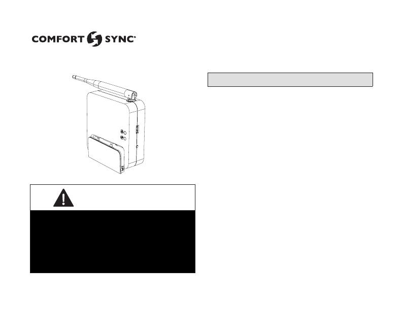
This Smart Hub replacement kit is used to
replace any previous version of the Comfort
Sync A3 thermostat smart hub component.
Read this entire document, noting which
procedures pertain to your specic
equipment and system requirements.
Make sure that all wiring conforms to local
and national building and electrical codes
and ordinances.
Do not Install on voltages higher than
30VAC.
Do not exceed 300 feet (91 meters) run
when using 18 or 22 AWG thermostat wire.
Do not allow load from any thermostat
connection to be more than 1 AMP.
2
Removing Old Smart Hub
1. Make note of homeowner account information and home Wi-Fi access information.
2. Go to the homeowner web portal and remove the original system from the account.
3. Disconnect power to the entire system.
4. Remove the access cover from Smart Hub.
5. Take a picture or make a drawing showing the control wires and what terminals they are
connected to.
6. Disconnect control wiring.
7. Remove all the screws securing the Smart Hub to wall.
8. Lift up and out to remove Smart Hub from the key hole.
9. Discard old Smart Hub.
3
Installing New Smart Hub
1. Remove new Smart Hub from
shipping container.
2. Remove the access cover
from the Smart Hub.
3. Mount the Smart Hub on the
wall with key hole support (see
“Installation Considerations”
on page 7).
4. Use the through-hole screw
previously removed to secure
the Smart Hub.
5. Reconnect all wiring that
was documented during the
removal of the old Smart Hub.
6. Replace the access cover.
7. Unfold the antenna and
position as noted during
removal of the original Smart
Hub.
8. Restore power to system.
1/4”
STRIP 1/4” INSULATION FROM
END OF EACH CONTROL WIRE
A
B
D
USE SMART HUB AS TEMPLATE TO MARK DESIRED MOUNTING
LOCATIONS ON WALL OR STUD.
CAUTION: DO NOT OVERTIGHTEN LOWER MOUNTING SCREW, MAY
DAMAGE SMART HUB.
SECURE SMART-HUB TO
WALL WITH
FIELD-PROVIDED
FASTENERS
RAER
TNORF
KEYHOLE
THROUGH-HOLE
C
MAKE CONNECTIONS TO SMART HUB
SCREW TERMINALS USING WIRING
DIAGRAMS PROVIDED
TERMINALS
(screw type)
+
-
COMMBUS
A B
R i+ I- C
ACC1 ACC2
+
-
COMMBUS
A B
R i+ I- C
ACC1 ACC2
4
Smart Hub LED Indicators, Terminals and External Components
System Status LED
System Commissioning
Status LED
USB Port
Dealer commissioning and
manual reboot button
Terminal Connection Access Cover
Antenna
5
Table 1. System and Commissioning Status Indicators
System Status Indicators
LED Color System Status Description
Green System is normal No system errors (Default state)
Red HVAC Error System has critical alert which needs installer attention.
Cyan Alerts Indoor unit is not connected or unable to communicate.
Magenta Thermostat Error HD display not connected.
Amber Wi-Fi
Either Wi-Fi is not connect, no Wi-FI is within range, or Wi-Fi
hardware error.
Commissioning Status Indicators
Blue System is normal
No mobile device is directly connected using Wi-Fi to the
Smart Hub.
Green LED is blinking
Commissioning button has been activated and Smart Hub is
awaiting for a connection with a mobile device.
Green LED is solid Mobile device is connected to the Smart Hub.
NOTE: When multiple errors are present the Smart Hub will display each condition for one second
on and one second o. Then it will display the next color error code indicator and continue
this sequence until all active errors have been displayed. Then all active errors are repeated
continuously. Display priority for these conditions are HVAC, Alerts, Thermostat and then Wi-Fi
errors.
6
Table 2. Smart Hub Terminal Designations, Order and Wiring
Requirements
Terminal
Designation
Description Thermostat Wiring
R 24VAC input 18AWG unshielded
I+ RS-BUS I+
22AWG shielded (recommended)
(2-pair conductor only)
I- RS-BUS I-
C 24VAC return 18AWG unshielded
ACC1 Accessory 1 and 2 (typically can be
used for 1 or 2 speed ventilators and
fresh air damper)
18AWG unshielded
ACC2
12+
12VDC output 18AWG unshielded
A
Communications bus A
22AWG shielded (recommended)
(2-pair conductor only)
B
Communications bus B
12-
12VDC return 18AWG unshielded
IMPORTANT
Use 2-pair, 18AWG unshielded thermostat cable (eld-provided) for power terminals (R, C, 12+
AND 12-). Recommend using 2-pair 22AWG shielded thermostat cable for communications
terminals (I+, I-, A and B) which will help eliminate any noise interference.
7
Installation Considerations
Things to consider when installing the Smart Hub:
Install the Smart Hub near the indoor unit such that there is a direct path to the approximate
location of the home Wi-Fi access point (the signal is not blocked by the indoor unit or duct
work, for example).
The Smart Hub can be attached to a vertical surface such as a wall stud or roof truss web, or
to a horizontal surface such as a oor or ceiling joist, or a roof rafter.
The Smart Hub antenna should be positioned such that they are roughly vertical, no matter the
orientation of the Smart Hub, itself.
Do not install the Smart Hub on the indoor unit, duct work, or other equipment that could
induce vibration in the Smart Hub.
Do not install the Smart Hub on or near large metal objects. This could adversely aect the
range and directional coverage of the Smart Hub Wi-Fi signal.
If the Smart Hub MUST be installed on a metal object, orientate the antenna perpendicular to
the metal surface.
In all cases, the Smart Hub antenna orientation may need to be adjusted to obtain best Wi-Fi
results.
8
  • Page 1 1
  • Page 2 2
  • Page 3 3
  • Page 4 4
  • Page 5 5
  • Page 6 6
  • Page 7 7
  • Page 8 8

Comfort Sync A3 User guide

Type
User guide
This manual is also suitable for

Comfort Sync A3 is a smart hub that connects your home's heating, ventilation, and air conditioning (HVAC) system to your home Wi-Fi network, allowing you to control your home's comfort from anywhere using a mobile device. With Comfort Sync A3, you can adjust your thermostat, set schedules, and monitor your energy usage. You can also receive alerts if there are any problems with your HVAC system. Comfort Sync A3 is easy to install and use, and it can help you save money on your energy bills.

Ask a question and I''ll find the answer in the document

Finding information in a document is now easier with AI