Page is loading ...

INSTALLATION GUIDE
1100X Wireless Receivers
Description
The 1100X Wireless Receiver is compatible with all DMP wireless devices. The receiver provides two-way, supervised
communication using 900 MHz frequency hopping-spread-spectrum technology. The receiver can be mounted up to 1,000 feet
from the panel enclosure. The receiver provides up to 500 wireless zones. Refer to the panel installation guide for number of
available wireless zones.
Compatibility
• XR150/XR550 Series panels
What is Included
• One Model 1100X Wireless Receiver
• One 4-wire Harness
• Hardware pack
Compliance Instructions
For applications that must conform to a National Recognized Testing Laboratory certicated system, please see the Listed
Compliance Specications section at the end of this guide for additional instructions.
Installing the Wireless Receiver
Selecting a Location
Choose an optimum location to mount the receiver. The 1100X Wireless Receiver is typically mounted at a distance not to
exceed 1000 feet away from the panel enclosure. A location should be selected that is centrally located between the 1100 Series
transmitters used in the installation. Install the receiver away from large metal objects. Mounting the receiver on or near metal
surfaces impairs performance. Do not use shielded wire between the panel and receiver. When selecting the proper mounting
location of a transmitter, refer to the LED Survey Operation section of the specic installation guide for the transmitter being
installed.
Tamper Switches
The 1100X is equipped with a case tamper and a wall tamper.
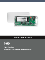
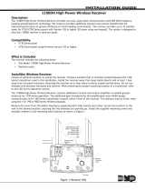
Mounting the Receiver
1. Remove the cover from the plastic housing by squeezing both sides toward each other.
2. Secure the receiver to the wall ensuring the two antennas are pointing up and the wall tamper switch makes proper
contact with the wall. Use the supplied screws in the mounting hole locations as shown in Figure 1.
U5
1
PANEL
J3
1
Power
RXD
TXD
Status
RF RXD
RF TXD
J4
1
U4
1
U7
J1
1
Mounting Hole
Locations
Squeeze to
Remove Cover
Squeeze to
Remove Cover
Connects
To Panel
Mounting Screw
Shoulder Washer
Power
Panel Receive
Panel Transmit
Status
RF Receive
RF Transmit
LEDs
Tamper
Switch
Figure 1: Receiver PCB

Digital Monitoring Products 1100X Wireless Receiver Installation Guide
2
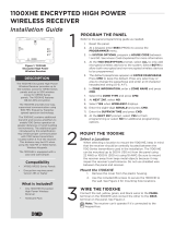
Wireless Bus Connection
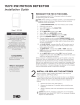
On XR150/XR550 Series panels, the 1100X interfaces using the on-board X-Bus connection.
Note: The 1100X Wireless Receiver cannot operate if connected to the Keypad Bus.
Harness Connection XR150/XR550 panels
1. Connect the PANEL header on the 1100X to the XR150/XR550 panel X-BUS header.
2. After power-up, briey reset the panel using the RESET jumper to activate wireless zone operation.
3. In System Options, program the House Code (1-50). In Zone Information, program the wireless zones.
3. Snap the cover back on the unit. The panel immediately recognizes the 1100X Receiver if the panel is programmed with a
house code.
Figure 2: XR150/XR550 DMP Wireless Bus Connection
1100X Receiver Operation
The 1100X receiver automatically sends the panel house code to wireless transmitters when the unique transmitter serial
number is programmed into the panel. The house code identies the panel, receiver, and transmitters to each other. The
receiver only listens for transmissions using the specied house code and/or programmed transmitter serial number.
Note: When setting up a wireless system, it is recommended to program zones and connect the receiver before
installing batteries in the transmitters.
Transmitters can be programmed for supervised operation. When programmed as supervised, the transmitter must
communicate with the receiver within the programmed number of minutes. If the transmitter fails to communicate, the
panel displays a missing condition.
Note: When a receiver is installed, powered up, or the panel is reset, the supervision time for transmitters is reset. If the
receiver has been powered down for more than one hour, wireless transmitters may take up to an additional hour to send
a supervision message unless tripped, tampered, or powered up. This operation extends battery life for transmitters. A
missing message may display on the keypad until the transmitter sends a supervision message.
When any wireless zone programming is changed in the panel, receiver zone programming is updated. At that point, all
wireless zones display as normal for approximately one minute, regardless of the actual state of the contact.
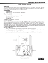
1100X LED Operation
Six LEDs display receiver operation and activity. Refer to the table below as required.
PCB LEDs Label Operation
Power
RXD
TXD
Status
RF RXD
RF TXD
POWER Steady green to indicate there is power to the receiver.
RXD Flashes yellow to indicate data is being received from the panel.
TXD Flashes green to indicate data is being sent to the panel.
STATUS Steady red to indicate memory upload. O when upload is complete.
RF RXD Flashes yellow to indicate data is being received from a transmitter.
RF TXD Flashes green to indicate data is being sent to a transmitter.
Black
Green
Yellow
Red
Can be extended
up to 100 feet
from the panel
using 22 AWG
or 250 feet
usin
g
18 AWG
XR150/XR550
Series Panel
Battery Start
Power
LED
U5
1
PANEL
J3
1
RED
Power
RXD
TXD
Status
RF RXD
RF TXD
J4
1
U4
1
U7
J1
1
1100X
Receiver
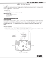
REC - Receive LED
XMT - Transmit LED

1100X Wireless Receiver Installation Guide Digital Monitoring Products
3
Transmitter Survey LED Operation
DMP 1100 Series transmitters provide Two-way (transmit acknowledge) operation. This advanced data protocol allows each
transmitter to conrm that each of its messages (alarm, checkin, tamper, low battery) are received and acknowledged
by the 1100 Series receiver. The conrmation is indicated visually by use of an LED on each transmitter. This Survey LED
should be used during installation to test each transmitter for proper operation. A full denition of the Survey LED follows.
The red LED on an 1100 Series transmitter turns on when the processor wakes up to send a message. Then after a series
of communication steps are completed (successful or not), the LED turns o when the processor goes back to sleep. 99.9%
of the time the processor is asleep in normal operation. The following list summarizes various indications that can be
observed on the LED and a denition for each. Note this is for a single message. Example, pressing and holding the tamper
switch.
Single 1/16 second ash
• Processor wakes up
• Transmitter receives immediate synchronization from receiver
• Transmitter transmits
• Transmitter receives immediate acknowledgement from receiver
• Processor goes to sleep
Single Pulse greater than 1/16 second but shorter than 8 seconds
• Processor wakes up
• Transmitter receives synchronization from receiver - possibly not immediate
• Transmitter transmits
• Transmitter receives acknowledgement from receiver - possibly not immediate
• Processor goes to sleep
Steady for 8 seconds
• Processor wakes up
• Transmitter never receives synchronization from receiver, or might receive synchronization
• Transmitter transmits if synchronization was received
• Transmitter never receives any further data from receiver
• Processor times out and goes to sleep
Multiple short ashes
• Processor wakes up
• Transmitter receives synchronization from receiver
• Transmitter transmits
• Transmitter receives data from receiver, but not a valid acknowledgement
• Processor briey goes to sleep
• Entire sequence is repeated, each short ash indicates a cycle

Digital Monitoring Products 1100X Wireless Receiver Installation Guide
4
Troubleshooting Using the Transmitter Survey LED
If a transmitter is unable to reliably communicate a message to the receiver, or is reported as missing, the Survey LED can
be used to help diagnose the issue. If the missing transmitter cannot be explained by obvious reasons such as a damaged
transmitter, failed battery, or changes in building construction; then the Survey LED should be used.
To use the Survey LED operation to help diagnose a eld issue, complete the following steps on an 1100 Series transmitter.
Repeat the following sequence 5 times and write down the LED operation for each tamper switch action.
• Press and hold the tamper switch
• Observe the LED until it turns o for at least 5 seconds
• Release the tamper switch
• Observe the LED until it turns o for at least 5 seconds
You now have observed the LED 10 times. Based on the results you have recorded use the list below to assist in
troubleshooting.
LED turns on a single time for less than 1 second 8 to 10 times.
• System is working properly
LED turns on for more than 1 second 3 to 9 times.
• The transmitter or receiver needs to be relocated
LED turns on for more than 1 second all 10 times.
• The receiver is not turned on, or is not operating
• The transmitter is not programmed into the receiver
• The transmitter or receiver needs to be relocated
LED ashes multiple times with a single tamper press or release 3 to 10 times.
• The transmitter or receiver needs to be relocated
LED never turns on.
• The transmitter battery is dead
• The tamper switch is being pressed or released too quickly
• The tamper switch or other part of the transmitter is broken
LED stays on constantly and is dim
• The transmitter battery is almost dead
• The transmitter is broken
General Wireless Troubleshooting
If ALL wireless devices do not operate, refer to the following checklist:
• Verify the receiver is an 1100X and the panel is an XR150/XR550 Series panel.
or
Verify the PANEL header from the receiver is connected to XBUS header on the XR150/XR550 panel.
• Briey reset panel using RESET jumper to activate wireless operation and wait one minute to test wireless zone(s).
• Verify the House Code (1-50) is programmed in System Options.
• Verify appropriate zone numbers are assigned as wireless zones.
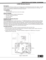
• Verify that the panel XMIT and REC LEDs alternately ash on and o at a rate of 1/4 second each. If the LEDs are On
steady or O, the panel and receiver are not communicating properly. (See Figure 3).
• Verify the 1100X LEDs operate correctly as listed in 1100X LED Operation.
• Verify transmitters have batteries correctly inserted.

1100X Wireless Receiver Installation Guide Digital Monitoring Products
5
Listed Compliance Specications
Commercial Fire
Transmitters must be programmed as supervised. Refer to the Transmitter Supervision Time table for the supervision time.
The maximum line impedance of the 4-wire bus is 16.2 Ohms for 1000 feet.
The recommended wire gauge for panel to receiver connection is 22 AWG.
After all transmitters are in position, the WLS option of the panel’s Walk Test must be operated and all transmitters programmed
for Fire (FI) or Supervisory (SV) must show that their checkin message was received. Refer to the panel programming guide for
Trip Counter for DMP Wireless check-in Test (WLS) which describes that both numbers of the counter must match. If not and a
failed wireless zone is displayed at END, decrease that transmitters range with the receiver and perform the WLS Walk Test again.
Transmitter Supervision Time
For UL Listed installations, program the transmitter supervision time in panel zone programming as listed in the following
table. Refer to the panel programming guide for complete wireless programming information.
UL Listing Listed Accessories Supervision
Time
UL 1023 Household Burglary Alarm System Units Accessory 1100R Repeater
1101/1102/1103/1106 Universal Transmitters
1127W/1127C PIR Motion Detector
1135 Wireless Sounder
1142 Two-Button Hold-Up Transmitter
9060/9063 Wireless Keypad
60
UL 636 Holdup Alarm Units and Systems Accessory 1142 Two-Button Hold-Up Transmitter 60
UL 634 Connections and Switches for use with Burglar Alarm
Systems Accessory 1100R Repeater
1101/1102/1103/1106 Universal Transmitters 60
UL 639 Intrusion Detection Units Accessory 1100R Repeater
1127W/1127C PIR Motion Detector 60
UL 365 Police Station Connected Burglar Accessory 1100R Repeater
1103 Universal Transmitter 60
UL 609 Local Burglar Alarm Units and System Accessory 1100R Repeater
1103 Universal Transmitter 60
UL 1076 Proprietary Burglar Alarm Units Accessory 1100R Repeater
1103 Universal Transmitter 60
UL 1610 Central Station Burglar Alarm Units Accessory 1100R Repeater
1103 Universal Transmitter
1135 Wireless Sounder
9060/9063 Wireless Keypad
60
UL 268 Smoke-Automatic Fire Detectors 1100R Repeater
1164 Wireless Synchronized Smoke Detector 3
UL 521 Heat Detectors for Fire Protective Signaling Systems 1100R Repeater
1183-135F/1183-135R Heat Detector 3
UL 985 Household Fire Warning System Accessory 1100R Repeater
1135 Wireless Sounder
9060/9063 Wireless Keypad
240
UL 864 Fire Protective Signaling Systems 1103 Universal Transmitter
1100R Repeater 3
UL 2075 Gas and Vapor Detectors and Sensors 1184 Wireless Carbon Monoxide Detector 240

800-641-4282
INTRUSION • FIRE • ACCESS • NETWORKS
www.dmp.com 2500 North Partnership Boulevard
Designed, Engineered and
Assembled in U.S.A. Springeld, Missouri 65803-8877
LT-0708 1.05 © 2017 Digital Monitoring Products, Inc.
17443
FCC Information
This device complies with Part 15 of the FCC Rules. Operation is subject to the following two conditions
(1) This device may not cause harmful interference, and
(2) this device must accept any interference received, including interference that may cause undesired operation.
Changes or modications made by the user and not expressly approved by the party responsible for compliance could void the
user’s authority to operate the equipment.
Note: This equipment has been tested and found to comply with the limits for a Class B digital device, pursuant to part 15 of the
FCC Rules. These limits are designed to provide reasonable protection against harmful interference in a residential installation.
This equipment generates, uses and can radiate radio frequency energy and, if not installed and used in accordance with the
instructions, may cause harmful interference to radio communications. However, there is no guarantee that interference will not
occur in a particular installation. If this equipment does cause harmful interference to radio or television reception, which can be
determined by turning the equipment o and on, the user is encouraged to try to correct the interference by one or more of the
following measures:
- Reorient or relocate the receiving antenna.
- Increase the separation between the equipment and receiver.
- Connect the equipment into an outlet on a circuit dierent from that to which the receiver is connected.
- Consult the dealer or an experienced radio/TV technician for help.
Note: The 1100 Series wireless system is a two-way supervised wireless design compliant with FCC rules as they pertain to 900
MHz Spread Spectrum devices. In rare instances it has been observed that certain 900 MHz cordless telephones may occasionally
experience a clicking sound on the telephone while in use. If this occurs, it may be resolved by selecting a dierent channel on
the cordless telephone, or replacing the cordless phone with a dierent brand or model of 900 MHz telephone or other cordless
telephone.
To comply with RF exposure requirements, a minimum distance of 20cm must be maintained between the antenna and all persons.
Industry Canada Information
This device complies with Industry Canada Licence-exempt RSS standard(s). Operation is subject to the following two conditions:
1. This device may not cause interference, and
2. this device must accept any interference, including interference that may cause undesired operation of the device.
Le présent appareil est conforme aux CNR d’Industrie Canada applicables aux appareils radio exempts de licence. L’exploitation
est autorisée aux deux conditions suivantes:
1. l’appareil ne doit pas produire de brouillage, et
2. l’utilisateur de l’appareil doit accepter tout brouillage radioélectrique subi, même si le brouillage est susceptible d’en
compromettre le fonctionnement.
This system has been evaluated for RF Exposure per RSS-102 and is in compliance with the limits specied by Health Canada
Safety Code 6. The system must be installed at a minimum separation distance from the antenna to a general bystander of 7.87
inches (20 cm) to maintain compliance with the General Population limits.
L’exposition aux radiofréquences de ce système a été évaluée selon la norme RSS-102 et est jugée conforme aux limites établies
par le Code de sécurité 6 de Santé Canada. Le système doit être installé à une distance minimale de 7.87 pouces (20 cm)
séparant l’antenne d’une personne présente en conformité avec les limites permises d’exposition du grand public.
Specications
Operating Voltage 8.0 to 14VDC
Current Draw 46mA
RF Power Rating 27mW
Frequency Range 905-924 MHz
Dimensions
Receiver Housing 4.65” L x 3.1” W x 1.4” H
Antennas 8.6” H
Color White
Housing Material Flame retardant ABS
Patents
U. S. Patent No. 7,239,236
Certications
California State Fire Marshal (CSFM)
FCC Part 15: CCK1100
Industry Canada: 5251A-PC0082
New York City (FDNY COA #6167)
Underwriters Laboratory (UL) Listed
ANSI/UL 365 Police Station Connected Burglar
ANSI/UL 609 Local Burglar Alarm Units and Systems
ANSI/UL 634 Connections and Switches for use with
Burglar Alarm Systems Accessory
ANSI/UL 636 Holdup Alarm Units and System
ANSI/UL 639 Intrusion Detection Units Accessory
ANSI/UL 1023 Household Burglar Alarm System Units
ANSI/UL 1076 Proprietary Burglar Alarm Units
ANSI/UL 1610 Central Station Burglar Alarm Units
ANSI/UL 864 Fire Protective Signaling Systems
ANSI/UL 985 Household Fire Warning System
/