Page is loading ...

NetSure™ 7100
-48 VDC Power System
Installation Manual
Specification Number: 582127000600, 582127000601, 582127000900, 582127000901
Model Number: 7100

Vertiv™ NetSure™ 7100 -48 VDC Power System Installation Manual
Vertiv™ NetSure™ 7100 -48 VDC Power System Installation Manual
The information contained in this document is subject to change without
notice and may not be suitable for all applications. While every precaution has
been taken to ensure the accuracy and completeness of this document, Vertiv
assumes no responsibility and disclaims all liability for damages resulting from
use of this information or for any errors or omissions. Refer to other local
practices or building codes as applicable for the correct methods, tools, and
materials to be used in performing procedures not specifically described in
this document.
The products covered by this instruction manual are manufactured and/or
sold by Vertiv. This document is the property of Vertiv and contains
confidential and proprietary information owned by Vertiv. Any copying, use or
disclosure of it without the written permission of Vertiv is strictly prohibited.
Names of companies and products are trademarks or registered trademarks of
the respective companies. Any questions regarding usage of trademark
names should be directed to the original manufacturer.
Technical Support Site
If you encounter any installation or operational issues with your product, check the pertinent section of this
manual to see if the issue can be resolved by following outlined procedures.
Visit https://www.vertiv.com/en-us/support/ for additional assistance.

Vertiv™ NetSure™ 7100 -48 VDC Power System Installation Manual
Proprietary and Confidential © 2023 Vertiv Group Corp.
iii
TABLE OF CONTENTS
Admonishments Used in this Document .............................................................................................................................. v
Important Safety Instructions ................................................................................................................................................. vi
Safety Admonishments Definitions ......................................................................................................................................................................................................................... vi
Safety and Regulatory Statements .......................................................................................................................................................................................................................... vi
Déclarations de Sécurité et de Réglementation .......................................................................................................................................................................................... vi
1 Customer Documentation Package ..................................................................................................................................1
2 Installation Acceptance Checklist ....................................................................................................................................1
3 Installing the System ............................................................................................................................................................ 2
3.1 General Requirements .............................................................................................................................................................................................................................................. 2
3.2 Mounting the System in an Equipment Rack ..................................................................................................................................................................................... 3
3.3 Installing Optional Lug Adapter Busbar Kits .......................................................................................................................................................................................4
3.4 Installing Optional EIB (Controller Extended Interface Board) .......................................................................................................................................... 5
3.5 Installing Circuit Breakers and Fuses ......................................................................................................................................................................................................... 7
4 Setting Jumper and Switch Options ............................................................................................................................. 10
4.1 Location of Circuit Cards with Jumper and Switch Options ............................................................................................................................................. 10
4.2 Jumper Settings on the System Interface Circuit Card .......................................................................................................................................................... 11
4.3 Switch Settings on the IB2 (Controller Interface Board) ........................................................................................................................................................ 12
4.4 Switch Settings on Optional EIB (Controller Extended Interface Board) ............................................................................................................... 13
5 Making Electrical Connections ....................................................................................................................................... 14
5.1 Important Safety Instructions ......................................................................................................................................................................................................................... 14
5.2 Wiring Considerations............................................................................................................................................................................................................................................ 14
5.3 Relay Rack / Equipment Cabinet Frame Grounding Connection ................................................................................................................................. 14
5.4 Power System Shelf Frame Grounding Connection ...................................................................................................................................................................15
5.5 Central Office Ground Connection .............................................................................................................................................................................................................15
5.6 AC Input and Equipment Grounding Connections (Nominal 208 VAC, 240 VAC, 277 VAC, Single Phase) ........................ 16
5.7 External Alarm, Reference, Monitoring, and Control Connections .............................................................................................................................. 19
5.7.1 Location of Circuit Cards with External Alarm, Reference, Monitoring, and Control Connectors ........................... 19
5.7.2 System Interface Circuit Card Connections (if required) ............................................................................................................................. 20
5.7.3 IB2 (Controller Interface Board) Connections (if required) ......................................................................................................................... 22
5.7.4 Optional EIB (Controller Extended Interface Board) Connections (if required) ....................................................................... 27
5.8 NCU Controller Ethernet Connection (if required) .................................................................................................................................................................... 32
5.9 Load Connections .................................................................................................................................................................................................................................................... 34
5.9.1 Load Connections to Distribution Panels and Load Return Busbars ................................................................................................ 34
5.9.2 Load Connections to an Optional Bullet Nose 6-Position GMT Distribution Fuse Block, P/N 549017 ............... 35
5.10 Battery Connections .............................................................................................................................................................................................................................................. 36
6 Installing Rectifier Modules..............................................................................................................................................37
7 Initially Starting, Configuring, and Checking System Operation ...................................................................... 38
7.1 Important Safety Instructions .........................................................................................................................................................................................................................38
7.2 Initial Startup Preparation ..................................................................................................................................................................................................................................38
7.3 Initially Starting the System .............................................................................................................................................................................................................................38
7.4 NCU Controller Initialization ............................................................................................................................................................................................................................38
7.5 Verifying and Setting the NCU Controller as Required for Your Application ................................................................................................... 40

Vertiv™ NetSure™ 7100 -48 VDC Power System Installation Manual
Proprietary and Confidential © 2023 Vertiv Group Corp.
iv
7.6 Checking System Status .................................................................................................................................................................................................................................... 43
7.7 Final Steps ....................................................................................................................................................................................................................................................................... 44

Vertiv™ NetSure™ 7100 -48 VDC Power System Installation Manual
Proprietary and Confidential © 2023 Vertiv Group Corp.
v
Admonishments Used in this Document
DANGER
! Warns of a hazard the reader will be exposed to that will likely result
in death or serious injury if not avoided. (ANSI, OSHA)
WARNING
! Warns of a potential hazard the reader may be exposed to that could
result in
death or serious injury if not avoided. This admonition is not used for situations that pose a
risk only to equipment, software, data, or service. (ANSI)
CAUTION
! Warns of a potential hazard the reader may be exposed to that could
result in minor or moderate injury if not avoided. (ANSI, OSHA) This admonition is not
used for situations that pose a risk only to equipment, data, or service, even if such use
appears to be permitted in some of the applicable standards. (OSHA)
ALERT
! Alerts the reader to an action that must be avoided in order to protect
equipment, software, data, or service. (ISO)
ALERT
! Alerts the reader to an action that must be performed in order to prevent
equipment damage, software corruption, data loss, or service interruption. (ISO)
FIRE SAFETY
! Informs the reader of fire safety information, reminders, precautions,
or policies, or of the locations of fire
-fighting and fire-safety equipment. (ISO)
SAFETY
! Informs the reader of general safety information, reminders, precautions, or
policies not related to a particular source of hazard or to fire safety. (ISO, ANSI, OSHA)

Vertiv™ NetSure™ 7100 -48 VDC Power System Installation Manual
Proprietary and Confidential © 2023 Vertiv Group Corp.
vi
Important Safety Instructions
Safety Admonishments Definitions
Definitions of the safety admonishments used in this document are listed under “Admonishments Used in this Document” on page v.
Safety and Regulatory Statements
Refer to Section 4154 (provided with your customer documentation) for Safety and Regulatory Statements.
Déclarations de Sécurité et de Réglementation
Reportez-vous à la Section 4154 (fourni avec les documents de votre client) pour les déclarations de sécurité et de réglementation.

Vertiv™ NetSure™ 7100 -48 VDC Power System Installation Manual
Proprietary and Confidential © 2023 Vertiv Group Corp.
1
1 Customer Documentation Package
This document (IM582127000900) provides Installation Instructions for Vertiv™ NetSure™ 7100 -48 VDC Power System, Spec. No.
582127000; Lists 600, 601, 900, and 901 only.
The complete Customer Documentation Package for Lists 600, 601, 900, and 901 consists of…
-48 VDC Power System Installation Manual
• Power System Installation Instructions: IM582127000900
-48 VDC Power System User Manual
• Power System User Instructions: UM582127000900
NCU Controller User Manual
• NCU Controller User Instructions: UM1M830BNA
USB Drive with All Customer Documentation
Applicable documents for this system are as follows.
• Power System Installation Instructions: IM582127000900 (instructions for Lists 600, 601, 900, and 901)
• Power System User Instructions: UM582127000900 (instructions for Lists 600, 601, 900, and 901)
• NCU Controller User Instructions: UM1M830BNA
• Rectifier Instructions: UM1R483500e3
• Power System “System Application Guide”: SAG582127000
• Engineering Drawings
• Also, provided on the USB drive is a controller configuration drawing and the controller configuration files loaded into the
controller as shipped.
2 Installation Acceptance Checklist
Provided in this section is an Installation Acceptance Checklist. This checklist helps ensure proper installation and initial operation of
the system. As the procedures presented in this document are completed, check the appropriate box on this list. If the procedure is
not required to be performed for your installation site, also check the box in this list to indicate that the procedure was read. When
installation is done, ensure that each block in this list has been checked. Some of these procedures may have been factory performed
for you.
NOTE! The system is not powered up until the end of this checklist.
NOTE! Some of these procedures may have been performed at the factory for you.
Installing the System
System Secured to the Equipment Rack
Optional Lug Adapter Busbar Kits Installed (if required)
Circuit Breakers Installed (if required)

Vertiv™ NetSure™ 7100 -48 VDC Power System Installation Manual
Proprietary and Confidential © 2023 Vertiv Group Corp.
2
Fuses Installed (if required)
Setting Jumper and Switch Options
Jumper on System Interface Circuit Card Set
Factory Switch Setting on IB2 (Controller Interface Board) Verified
Factory Switch Setting on Optional EIB (Controller Extended Interface Board) Verified
Making Electrical Connections
System Frame Ground Connection Made
Central Office Ground Connection Made
AC Input and AC Input Equipment Grounding Connections Made
External Alarm, Reference, Monitoring, and Control Connections Made
NCU Controller Ethernet Port Connection Made (if required)
NCU Controller Second Ethernet Port Connection Made (if required)
Load Connections Made
Battery Connections Made
Installing Rectifier Modules
Rectifier Modules Installed
Initially Starting the System
System Started, Configured, and Checked
3 Installing the System
3.1 General Requirements
• This product is intended only for installation in a restricted access location on or above a non-combustible surface.
• This product must be located in a controlled environment with access to crafts persons only.
• This product is intended for installation in network telecommunication facilities (CO, vault, hut, or other environmentally
controlled electronic equipment enclosure).
• This product is intended for connection to the common bonding network in a network telecommunication facility (CO, vault,
hut, or other environmentally controlled electronic equipment enclosure).
• The DC return connection to this system can remain isolated from system frame and chassis (DC-I).
• The installer should be familiar with the installation requirements and techniques to be used in securing the system to an
equipment rack.
• The system must be mounted in an environment that does not exceed the rated operating ambient temperature range found
in SAG582127000.

Vertiv™ NetSure™ 7100 -48 VDC Power System Installation Manual
Proprietary and Confidential © 2023 Vertiv Group Corp.
3
• Clearance Requirements:
- Recommended minimum clearance for the front of the system is 2' 6”.
- Recommended minimum clearance for the rear of the system is 2’ 0”.
3.2 Mounting the System in an Equipment Rack
This power system is designed to mount in a 23-inch wide rack having 1-inch or 1-3/4-inch multiple drillings. Refer to System
Application Guide SAG582127000 for overall dimensions. Perform the following steps to mount the power system.
DANGER! The power system is heavy. Use a hoist, battery lift, or other appropriate lifting device to raise and support the
power system during the installation. Take appropriate precautions to avoid injury.
NOTE! Refer to “General Requirements” on page 2 for mounting restrictions and ventilation requirements.
NOTE! The power system consists of a distribution cabinet and module mounting assemblies. The distribution cabinet is
factory connected to the module mounting assemblies. The distribution cabinet with module mounting assemblies is
mounted as a complete assembly.
Procedure
1. Position the power system in the equipment rack.
NOTE! In the next steps, install (orient) the ground washers so the teeth dig into the mounting angles for a secure ground
connection.
NOTE! Compliance with Telcordia GR-1089-CORE requires that prior to mounting the system to the equipment rack:
- All paint must be removed from the front surface of each equipment rack rail where it mates with a shelf-mounting
bracket, so that good metal-to-metal contact can be established between the shelf and rack.
- The shelf-to-rack mating surfaces must be cleaned.
- Electrical anti-oxidizing compound must be applied to the shelf-to-rack mating surfaces.
2. Secure the power system to the equipment rack using hardware as shown in Figure 3.1. Use grounding washers at all
locations. Torque connections to the value indicated in Figure 3.1.
Figure 3.1: Mounting the Power System in an Equipment Rack
Front
MOUNTING HARDWARE
12-24 x 3/4" Thread Forming Hex
Head Screw
No. 10/12 Ground Washer
Torque: 65 in-lbs.

Vertiv™ NetSure™ 7100 -48 VDC Power System Installation Manual
Proprietary and Confidential © 2023 Vertiv Group Corp.
4
3.3 Installing Optional Lug Adapter Busbar Kits
These kits provide lug adapter busbars plus hardware for use with 2-pole and 3-pole circuit breakers. A right-angle kit is also
available for 1-pole devices.
Procedure
1. Refer to Figure 3.2 to install the lug adapter busbars kits.
Figure 3.2: Installing Optional Lug Adapter Busbar Kits
Install on return bus.
Busbar Adapter
Kit P/N 559805
Busbar Adapter
Kit P/N 559804
Busbar Adapter
Kit P/N 559803
Circuit breaker locations for reference only.
-48 VDC Load
Connections
-48 VDC Load
Connections
Load Return
Connections
Apply anti-oxidizing compound to busbar mating surfaces
before assembling. Recommended torque is 75 in-lbs
using the supplied 1/4” bolts and hardware. Recommended
torque is 300 in-lbs using the supplied 3/8” bolts and hardware.
559804559803 559805

Vertiv™ NetSure™ 7100 -48 VDC Power System Installation Manual
Proprietary and Confidential © 2023 Vertiv Group Corp.
5
3.4 Installing Optional EIB (Controller Extended Interface Board)
An EIB (Controller Extended Interface Board) can be installed inside the distribution cabinet. This option is factory installed if ordered
with the system. Refer to the following procedure to field install this option.
Procedure
1. Performing this procedure may activate external alarms. Do one of the following. If possible, disable these alarms. If these
alarms cannot be easily disabled, notify the appropriate personnel to disregard any future alarms associated with this system
while the procedure is being performed.
DANGER! Performing the next steps exposes service personnel to battery potential. Exercise extreme caution not to
inadvertently contact or have any tool inadvertently contact any energized electrical termination.
2. Open the distribution cabinet’s front door.
WARNING! Damage to the circuit card may result if the next step is not followed.
3. Connect an approved grounding strap to your wrist. Attach the other end to a suitable ground.
4. Set the switch on the EIB board as outlined in “Switch Settings on Optional EIB (Controller Extended Interface Board)” on
page 13.
5. Refer to Figure 3.3 and install the EIB board inside the distribution cabinet.
6. Locate the I2C connector bundled at the bottom of the distribution cabinet. Route this cable to the newly installed EIB board.
Cut cable ties as required. Plug this connector into the mating I2C connector located on the EIB board. Refer to Figure 3.3.
Dress and secure the cable as required.
7. Make external connections to the EIB board as required. See “Optional EIB (Controller Extended Interface Board)
Connections (if required)” on page 27.
8. Remove the grounding wrist strap.
9. Reboot the Controller
Local Menu Navigation: At the Main Screen, press ENT and ESC at the same time to reset the NCU Controller.
Web Menu Navigation: Go to Advance Settings Menu / SW Maintenance Tab / Reboot Controller button.
10. Close the distribution cabinet’s front door.
11. Enable the external alarms or notify appropriate personnel that this procedure is finished.
12. Ensure that there are no local or remote alarms active on the system.

Vertiv™ NetSure™ 7100 -48 VDC Power System Installation Manual
Proprietary and Confidential © 2023 Vertiv Group Corp.
6
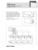
Figure 3.3: Installing Optional EIB (Controller Extended Interface Board)
I2C Connector
Front
Optional
EIB (Extended Interface Board)
(installed at bottom of shelf)
Front
Panel
Removed
EIB Assembly
(exploded view)
EIB Assembly

Vertiv™ NetSure™ 7100 -48 VDC Power System Installation Manual
Proprietary and Confidential © 2023 Vertiv Group Corp.
7
3.5 Installing Circuit Breakers and Fuses
Circuit breakers and/or fuses may have been factory installed for you. If so, verify their positions and sizes.
Installing Bullet Nose Type Circuit Breakers
CAUTION! See SAG582127000 for temperature, sizing, and spacing restrictions. Refer to SAG582127000 for any other
restrictions.
Refer to the following procedure and install appropriately sized bullet nose type circuit breakers into the proper mounting positions in
the distribution cabinet.
Procedure
1. Open the distribution cabinet’s front door.
2. Ensure that the circuit breaker is in the OFF position and is of the correct rating. Orient the circuit breaker as shown in Figure
3.4. Insert the terminals on the rear of the circuit breaker into their corresponding sockets on the distribution panel. Ensure
the alarm contact on the back of the circuit breaker makes contact with the alarm terminal on the spring strip. Push
distribution device in firmly until fully seated in the distribution panel.
3. Record all circuit breaker sizes on the label provided on the shield.
4. Close and secure the distribution cabinet’s front door.
Figure 3.4: Installing a Bullet Nose Type Circuit Breaker
Installing Bullet Nose Type Fuseholders and TPS/TLS Fuses
CAUTION! See SAG582127000 for temperature, sizing, and spacing restrictions. Refer to SAG582127000 for any other
restrictions.
Refer to the following procedure and install bullet nose type fuseholders and appropriately sized TPS/TLS fuses into the proper
mounting positions in the distribution cabinet.
Procedure
1. Open the distribution cabinet’s front door.
2. Orient the fuseholder as shown in Figure 3.5. Insert the terminals on the rear of the fuseholder into their corresponding
sockets on the distribution panel. Ensure the alarm contact on the back of the fuseholder makes contact with the alarm
terminal on the spring strip. Push fuseholder in firmly until fully seated in the distribution panel.
Insert these terminals
into corresponding sockets
on distribution panel.
Longer Side
to the Bottom
Shorter Side
to the Top
Lettering on
handle must be
right side up.
Turn off
before installing.

Vertiv™ NetSure™ 7100 -48 VDC Power System Installation Manual
Proprietary and Confidential © 2023 Vertiv Group Corp.
8
3. When all fuseholders are installed, install an appropriately sized TPS/TLS fuse in each. To do this, remove the fuse carrier
from the mounted fuseholder body. Hold the fuseholder body while you pull the fuse carrier from the body. Slide the fuse in
place between the contacts of the fuse carrier. When done, push the fuse carrier back into the fuseholder body. Note that a
polarizing key on the bottom of the carrier prevents the carrier from being inserted upside down. See Figure 3.5.
4. Verify that an 18/100 ampere alarm fuse is present in each fuseholder and that a plastic safety cover is installed on this fuse.
5. Record all fuse sizes on the label provided on the shield.
6. Close and secure the distribution cabinet’s front door.
Figure 3.5: Installing a Bullet Nose Type Fuseholder and TPS/TLS Fuse
Fuseholder Assembly
Longer Side
to the Bottom
Shorter Side
to the Top
Fuse Carrier
Fuseholder Body
TPS/TLS Fuse
Polarizing Keyway
Matches Key on
Bottom of Fuse Carrier
Fuseholder Assembly
Exploded View
Fuseholder Assembly (P/N 117201) includes
body & carrier, alarm fuse, and alarm fuse safety cover.
Insert these terminals
into corresponding sockets
on distribution panel.
GMT-X
Safety Fuse Cover
(Replacement
P/N 248898700)
GMT-18/100A
Alarm Fuse
(Replacement
P/N 248610301)

Vertiv™ NetSure™ 7100 -48 VDC Power System Installation Manual
Proprietary and Confidential © 2023 Vertiv Group Corp.
9
Installing an Optional Bullet Nose Type 6-Position GMT Distribution Fuse Block (P/N 549017)
Procedure
1. Open the distribution cabinet’s front door.
2. Follow the steps in Figure 3.6.
3. Install an appropriately sized GMT fuse in each fuse mounting position on the GMT Distribution Fuse Block as required. If
dummy fuses are installed, first remove the dummy fuse.
a) Verify that dummy fuses are installed in all unused fuse positions on the GMT distribution fuse block.
b) Verify that a plastic safety cover is installed on all GMT fuses on the GMT distribution fuse block.
4. Record all fuse sizes (installed on the GMT distribution fuse block) on the label provided on the shield.
5. Close and secure the distribution cabinet’s front door.
Figure 3.6: Installing an Optional Bullet Nose Type 6-Position GMT Distribution Fuse Block (P/N 549017)
2. Plug in GMT Fuse Block.
1. Remove two lug terminal busbars for positions to be occupied
by GMT Fuse Block. Remove plastic busbar plugs first.
3. Connect supplied jumper from
GMT Fuse Block to Return Bar.
Torque to 75 in-lbs.
Part of P/N 549017
Part of P/N 549017

Vertiv™ NetSure™ 7100 -48 VDC Power System Installation Manual
Proprietary and Confidential © 2023 Vertiv Group Corp.
10
4 Setting Jumper and Switch Options
The various circuit cards inside the distribution cabinet contain jumper and/or switch options.
4.1 Location of Circuit Cards with Jumper and Switch Options
Refer to Figure 4.1.
Figure 4.1: Location of Circuit Cards with Jumper and Switch Options
Front
IB2 (Interface Board)
(installed at bottom of shelf)
Optional
EIB (Extended Interface Board)
(installed at bottom of shelf)
Front
Panel
Removed
System Interface Board
(installed on side panel)
CAN Bus
Termination
Resistor

Vertiv™ NetSure™ 7100 -48 VDC Power System Installation Manual
Proprietary and Confidential © 2023 Vertiv Group Corp.
11
4.2 Jumper Settings on the System Interface Circuit Card
Perform the following procedures to verify the factory settings and/or make the required settings per your site requirements. These
procedures can also be used to make adjustments on a replacement circuit card.
Controller Power Option
This option allows the controller to remain powered if a battery LVD contactor is furnished and it opens. The controller is powered
from the internal “system” bus. Rectifiers and battery are connected to this “system” bus, so the controller is powered both by the
rectifiers and by the battery. A jumper option allows the controller to be powered from the “system side” of a battery LVD contactor
(if furnished) or the “battery side” of a battery LVD contactor (if furnished). Refer to Figure 4.2 for circuit card location and jumper
location.
• Jumper in “No Battery Power” Position: The controller is powered from the “system side” of a battery LVD contactor (if
furnished). Note if a battery LVD contactor is not furnished, the controller is powered by both rectifiers and battery. If a
battery LVD contactor is furnished and opens, the controller is powered by the rectifiers (if functional).
If you lose AC power and your battery LVD contactor opens, the controller will shut down.
• Jumper in “Battery Power” Position: The controller is powered from the “battery side” of a battery LVD contactor (if
furnished). Note if a battery LVD contactor is not furnished, the controller is powered by both rectifiers and battery. If a
battery LVD contactor is furnished and opens, the controller is powered by the battery and the battery will drain. The
controller’s power consumption is 5W.
If you lose AC power and your battery LVD contactor opens, the controller will continue to operate.
Procedure
1. Refer to Figure 4.2 and place the jumper on J4 in the “Battery Pwr” or “No Battery Pwr” position.
Figure 4.2: System Interface Board Jumper Location and Settings
Rear
System Interface Board
(installed on side panel)
System Interface Board P/N 555484
J1
J2
J3
J4
J5
1
1
555484
0 0 0 X X X X X
A X X X X X X X X
1
No
Battery
Pwr
Battery
Pwr
Shorting
Jumper
J4 on System Interface Board
Selects to power controller
from “Battery Power” or not
if a battery LVD contactor is furnished.

Vertiv™ NetSure™ 7100 -48 VDC Power System Installation Manual
Proprietary and Confidential © 2023 Vertiv Group Corp.
12
4.3 Switch Settings on the IB2 (Controller Interface Board)
Dip Switch SW1 on the IB2 (Controller Interface Board) is used to set the communications address for this board. Refer to Table 4.1
for SW1 settings. Refer to Figure 4.1 for circuit card location. Refer to Figure 4.3 for SW1 location.
Perform the following procedure to verify the factory settings.
This procedure can also be used to make adjustments on a replacement circuit card.
Procedure
1. Ensure SW1 is set per Table 4.1. Refer to Figure 4.3 for location.
Table 4.1: IB2 Interface Board Switch Settings
Setting
DIP Switch SW1
1 2
IB2
OFF
OFF
Figure 4.3: IB2 Interface Board Switch Location and Settings
Setting DIP Switch SW1
1 2
IB2 OFF OFF
ON OFF
1
2
SW1
SW1
In this system, switch settings
must be in positions shown.
IB2 Circuit Card (Top View)
(Controller Interface Board)
ON OFF
1
2
-
J12
SW1
7
J2
J11
531
Relay Output Terminal BlocksDigital Input Terminal Blocks
J9J8J7J6J5J4J3
+
NOCNC
NOCNC
531 531 531 531
NOCNC
531
NOCNC
531
NOCNC
531
4 62 4 62 4 62 4 62
NOCNC
4 62
NOCNC
4 62
NOCNC
4 62
Relay
No.
Relay
No.
87654321
8642
87
6543
21
Input
No. (+)
Input
No. (
–
)
Switch SW1 is located in
this corner of the IB2 circuit card.

Vertiv™ NetSure™ 7100 -48 VDC Power System Installation Manual
Proprietary and Confidential © 2023 Vertiv Group Corp.
13
4.4 Switch Settings on Optional EIB (Controller Extended Interface Board)
Dip Switch SW1 on the EIB (Controller Extended Interface Board) is used to set the communications address for this board. Refer to
Table 4.2 for SW1 settings. Refer to Figure 4.1 for circuit card location. Refer to Figure 4.4 for SW1 location.
Perform the following procedure to verify the factory settings.
This procedure can also be used to make adjustments on a replacement circuit card.
Procedure
1. Ensure SW1 is set per Table 4.2. Refer to Figure 4.4 for location.
Table 4.2: Optional EIB Extended Interface Board Switch Settings
Setting
DIP Switch SW1
1 2
EIB
OFF
OFF
Figure 4.4: Optional EIB Extended Interface Board Switch Location and Settings
ON OFF
1
2
SW1
Setting DIP Switch SW1
21
EIB OFFOFF
SW1
In this system, switch settings
must be in positions shown.
EIB Circuit Card (Top View)
(Controller Extended Interface Board)
J4
SW1
J2
J3
J5 J6 J7 J8 J9
2 4 6
31 5
2 4 6
31 5
2 4 6
31 5
246
31 5
2 4 6
31 5
-
+
Shunt
Inputs
Voltage
Inputs
Voltage Inputs Relays
Sh1
V1
V2
V3 V5 V7 V8
V4 V6
RLY11RLY9
Sh2 Sh3
Sh1 Sh2 Sh3
NOCNC NOCNC NOCNC
NOCNC NOCNC
Relays
RLY13 RLY10 RLY12
Terminal Blocks
ON OFF
1
2
Switch SW1 is located in
this corner of the IB2 circuit card.

Vertiv™ NetSure™ 7100 -48 VDC Power System Installation Manual
Proprietary and Confidential © 2023 Vertiv Group Corp.
14
5 Making Electrical Connections
5.1 Important Safety Instructions
DANGER! Adhere to the “Important Safety Instructions” starting on page vi.
5.2 Wiring Considerations
All wiring and branch circuit protection should follow the current edition of the American National Standards Institute (ANSI)
approved National Fire Protection Association's (NFPA) National Electrical Code (NEC), and applicable local codes. For operation in
countries where the NEC is not recognized, follow applicable codes.
For wire size, branch circuit protection, crimp lug, and general wiring recommendations; refer to System Application Guide
SAG582127000.
Lugs should be crimped per lug manufacturer’s specifications.
Refer to Table 5.1 for supplemental lug crimping information when using the special application crimp lug / strap combination.
Table 5.1: Supplemental Lug Crimping Information when using the Special Application Crimp Lug / Strap Combination
Crimp Lug Part No.
Crimp Tool Required1,
T&B Model TBM12 or TBM15 Hydraulic Heads
Color Key Die Index/
Code No.
Die Cat.
Number
245393500 Burndy:
YA25L-4TCG1 Pink 42H 15508
245393600 Burndy:
YA26L-4TCG1
Black 45 15526
245393700 Burndy:
YA27L-4TCG1
Orange 50 15530
245393800 Burndy:
YA28L-4TCG1 Purple 54H 15511
514872
T & B:
256-30695-1879
Yellow 62 15510
Burndy:
YA29L-4TCG1
514873
T & B:
256-30695-1880
Red 71 15514
Burndy:
YA31L-4TCG1
1 The lugs should be crimped to the specifications given in the manufacturer’s instructions furnished with the crimp tool or lug.
5.3 Relay Rack / Equipment Cabinet Frame Grounding Connection
For relay rack / equipment cabinet frame grounding requirements, refer to the current edition of the American National Standards
Institute (ANSI) approved National Fire Protection Association's (NFPA) National Electrical Code (NEC), applicable local codes, and
your specific site requirements.
/