Broan 506 Installation guide

Category
Household fans
Type
Installation guide

This manual is also suitable for

WARNING
TO REDUCE THE RISK OF FIRE ELECTRIC SHOCK,
OR INJURY TO PERSONS, OBSERVE THE FOL-
LOWING:
1. Use this unit only in the manner intended by the
manufacturer. If you have questions, contact the
manufacturer at the address or telephone number
listed in the warranty.
2. Before servicing or cleaning unit, switch power off
at service panel and lock the service disconnecting
means to prevent power from being switched on
accidentally. When the service disconnecting means
cannot be locked, securely fasten a prominent warn-
ing device, such as a tag, to the service panel.
3. Installation work and electrical wiring must be done
by a qualified person(s) in accordance with all ap-
plicable codes and standards, including fire-rated
construction codes and standards.
4. Sufficient air is needed for proper combustion and
MODELS 506 & 507
CHAIN PULL FANS
MODELOS 506 y 507 VENTILADORES
CON TIRADOR DE CADENA
ADVERTENCIA
ADVERTENCIA PARA REDUCIR EL RIESGO DE INCENDIO, DES-
CARGA ELECTRICA O LESIONES PERSONALES, CUMPLA CON
LOS SIGUIENTES PUNTOS:
1. Solamente use esta unidad de la manera propuesta por el fabricante.
Si tiene alguna pregunta, póngase en contacto con el fabricante en
la dirección o teléfono anotados en la garantía.
2. Antes de limpiar o de poner en servicio la unidad, apague el
interruptor en el panel de servicio, y asegure el panel de servicio
para evitar que se encienda accidentalmente. Cuando el dispositivo
para desconectar el servicio eléctrico no puede ser cerrado con
algún tipo de traba, sujete fuertemente al panel de servicio, una
etiqueta de advertencia prominente.
3. El trabajo de instalación y el alambrado eléctrico deben de llevarse
a cabo por personal competente de acuerdo con todos los códigos
y las normas correspondientes, incluyendo los códigos y normas
de construcción contra incendios.
INSTALLER: Leave This Manual With The Homeowner. HOMEOWNER: Use and Care Information on Page 3.
INSTALADOR: Deje este manual con el dueño de la casa. DUEÑO DE LA CASA: Información del uso y cuidado en la página 3.
LEA Y CONSERVE ESTAS
INSTRUCCIONES
READ AND SAVE
THESE INSTRUCTIONS
506
507
exhausting of gases through the flue (chimney) of fuel burning equipment to
prevent backdrafting. Follow the heating equipment manufacturer’s guideline
and safety standards such as those published by the National Fire Protection
Association (NFPA), and the American Society for Heating, Refrigeration and
Air Conditioning Engineers (ASHRAE), and the local code authorities.
5. When cutting or drilling into wall or ceiling, do not damage electrical wiring
and other hidden utilities.
6. Ducted fans must always be vented to the outdoors.
7. If this unit is to be installed over a tub or shower, it must be marked as ap-
propriate for the application.
8. Install fan at least 5 feet above the floor.
9. Never place a switch where it can be reached from a tub or shower.
10. This unit must be grounded.
TO REDUCE THE RISK OF A RANGE TOP GREASE FIRE:
1. Never leave surface units unattended at high settings. Boilovers cause smok-
ing and greasy spillovers that may ignite. Heat oils slowly on low or medium
settings.
2. Always turn hood ON when cooking at high heat or when cooking flaming
foods.
3. Clean ventilating fans frequently. Grease should not be allowed to accumulate
on fan or filter.
4. Use proper pan size. Always use cookware appropriate for the size of the
surface element.
TO REDUCE THE RISK OF INJURY TO PERSONS IN THE EVENT OF A
RANGE TOP GREASE FIRE, OBSERVE THE FOLLOWING:*
1. SMOTHER FLAMES with a close-fitting lid, cookie sheet, or metal tray, then
turn off the burner. BE CAREFUL TO PREVENT BURNS. If the flames do
not go out immediately, EVACUATE AND CALL THE FIRE DEPARTMENT.
2. NEVER PICK UP A FLAMING PAN - You may be burned.
3. DO NOT USE WATER, including wet dishcloths or towels - a violent steam
explosion will result.
4. Use an extinguisher ONLY if:
A. You know you have a Class ABC extinguisher and you already know how
to operate it.
B. The fire is small and contained in the area where it started.
C. The fire department is being called.
D. You can fight the fire with your back to an exit.
*Based on “Kitchen Firesafety Tips” published by NFPA.
CAUTION
1. For general ventilating use only. Do not use to exhaust hazardous or explosive
materials and vapors.
2. To avoid motor bearing damage and noisy and/or unbalanced impellers,
keep drywall spray, construction dust, etc. off power unit.
3. Please read specification label on product for further information and require-
ments.
TOOLS AND MATERIALS REQUIRED
4. Se requiere una cantidad de aire suficiente para la combustion y expulsión de gases
por la chimenea en el equipo de quemado de combustible para evitar la retrogresión
de la llama. Siga las especificaciones del fabricante del equipo de calefacción y las
normas de seguridad semejantes a las publicadas por la Asociación nacional de
protección contra incendios (NFPA por sus siglas en inglés), y la Sociedad americana
de ingenieros de calefacción, refrigeración y aire acondicionado (ASHRAE), y los
códigos de las autoridades locales.
5. Cuando corte o taladre en una pared o techo, no dañe el alambrado eléctricos ni otras
instalaciones ocultas.
6. Los ventiladores con conconductos deben ser siempre ventilados hacia el exterior.
7. Si esta unidad va a ser instalada encima de un baño o ducha,debe ser marcada como
apropiada para dicha aplicación.
8. Instálelo por lo menos a 152 cm (5 pies) sobre el piso.
9. Nunca coloque un interruptor donde pueda ser alcanzado desde la bañera o la ducha.
10. Esta unidad debe ser conectada a tierra.
PARA REDUCIR EL RIESGO DE INCENDIO DEBIDO A GRASA ACUMULADA EN LAS
HORNILLAS:
1. Nunca deje sin atender las unidades de superficie cuando tengan ajustes altos. Los
reboses pueden provocar humo y derrames grasosos que se pueden incendiar.
Caliente lentamente el aceite en un ajuste bajo o medio.
2. Siempre ENCIENDA la campana cuando cocine con alta temperatura o cuando
cocine alimentos que se puedan incendiar.
3. Limpie con frecuencia los ventiladores. No debe permitir que la grasa se acumule en
el ventilador ni en el filtro.
4. Utilice un sartén de tamaño adecuado. Siempre utilice el utensilio adecuado al tama-
ño del elemento de superficie.
PARA REDUCIR EL RIESGO DE LESION A PERSONAS RESULTADO DE UN INCENDIO
DEBIDO A GRASA ACUMULADA EN LAS HORNILLAS, PROCURE LO SIGUIENTE:*
1. AHOGUE LAS LLAMAS con una tapa ajustada o charola de metal, después apague
la hornilla. TENGA CUIDADO A FIN DE EVITAR QUEMADURAS. Si las llamas no se
apagan de inmediato, EVACUE Y AVISE A LOS BOMBEROS.
2. NO LEVANTE NUNCA UNA SARTEN QUE ESTE EN LLAMAS - Usted se podrá quemar.
3. NO UTILICE AGUA, incluyendo toallas de cocina mojadas - puede resultar una explosión
de vapor violenta.
4. Utilice un extinguidor SOLAMENTE si:
A. Usted sabe que tiene un extinguidor de clas ABC y lo sabe utilizar.
B. El incendio es pequeño y contenido dentro del área donde se inició.
C. Los bomberos han sido avisados.
D. Usted puede combatir el incendio con una salida a su espalda.
* Basado en las recomendaciones para “Seguridad en la Cocina” publicadas por la NFPA
de los EEUU.
PRECAUCION
1. Solamente para uso de ventilación general. No se use para extraer materiales ni vapores
peligrosos o explosivos.
2. Para evitar daños al cojinete del motor y/o impulsores ruidosos o desequilibrados, mantenga
la fuente de potencia lejos de rocíos de pared seca, de polvo de construcción, etc.
3. Lea la etiqueta de especificaciones del proconducto para más información y requisitos.
HERRAMIENTAS Y MATERIALES
NECESARIOS
q Desmontador de cuchilla recta
q Taladro y brocas
q Martillo
q Alicates
q Cinta métrica o regla y lápiz
q Sierra circular
q Sierra saber o sierra de pared seca
q Artículos eléctricos del tipo necesario para cumplir con los códigos locales.
q Madera de 4
1
/
2
de 1 x 2 plg. para las tiras del contramarco
q Compuesto de sellado (silicona) de alta calidad.
q Straight blade screwdriver
q Drill and drill bits
q Hammer
q Pliers
q Tape measure or ruler and pencil
q Circular saw
To register this product visit
www.broan.com
q Saber saw or drywall saw
q Electrical supplies of type needed
to comply with local codes
q 4-
1
/
2
of 1” x 2” lumber for casing
strips
q High quality caulking compound.
FIG. 2
FIG. 3
OUTER HOUSING
CARCASA
EXTERIOR
INNER
HOUSING
CARCASA
INTERIOR
MOTOR
ASSEMBLY
CONJUNTO
DEL MOTOR
NOTE
Remove bottom knockout ONLY!
NOTA
Saque SOLAMENTE el disco
removible del fondo de la caja.
CENTER LOCATION FROM
INSIDE WALL
POSICIÓN DEL CENTRO
DESDE LA PARED INTERIOR
FIG. 4
5 FEET MINIMUM
ABOVE FLOOR
MÍNIMO DE
152,4 CM
(5 PIES) SOBRE
EL SUELO
506 507
A 10-1/4" 8-1/4"
26,03 CM 20,95 CM
14-1/2"
36,83 CM
14-1/2"
36,83 CM
TYPICAL INSTALLATION
This unit mounts in walls 4-1/2” to 9-1/2” thick. Outside
housing flange is fastened to casing strips. If sheath-
ing behind siding is not wood, provide extra supports
between walls, nailed or screwed to siding. (FIG. 1)
PREPARE FAN
1. Remove motor assembly by loosening mounting
screws, rotating assembly, and lifting it out of inner
housing.
2. Use care when handling motor bracket assembly to
prevent damage to blade. Do not set down assembly
with weight of motor resting on the blade.
3. Pull inner housing out of outer housing. (FIG. 2)
4. Remove knockout from bottom of wiring box (pro-
vided in parts bag). (FIG. 3)
INSTALL FAN
5. From inside room, choose fan location. Make sure
that wall stud does not run through location. Lay out
housing opening on wall. (FIG. 4)
INSTALLER - PLEASE NOTE:
Center of housing opening must be a minimum
of 5 feet above the floor.
If fan will be installed higher than 5 feet above
the floor: Make sure that user(s) can comfort-
ably reach chain and can pull chain in and out
horizontally to operate.
6. Transfer center of circle to outside wall.
7. Cut out round hole on inside wall.
8. On outside wall, lay out 14-
1
/
2
square around marked
center location. (FIG. 5)
9. Cut hole in siding only. DO NOT CUT SHEATHING.
Nail down all loose ends.(FIG. 6)
10. Cut round hole in sheathing.
11. Install 1” x 2” casing strips on side of square. (FIG. 7)
12. Measure wall thickness and remove appropriate
knockout(s). (FIG. 8)
13. Put large bead of caulk on inside of outer housing
flange. Insert outer housing into hole in outside wall
and use inner housing to test the fit.
14. Nail or screw outer housing to casing strips. Caulk
all around outside of flange and casing strips. Do
not fasten door closed.
15. Run wiring to installation location.
16. Remove chain and switch trigger from parts bag.
Thread chain through chain lock on inner housing
then through switch trigger, emboss on inner hous-
ing, and attach to clip on door of outer housing. (FIG.
9)
17. Insert inner housing into wall and pull wiring through
opening in housing. Use (3) black sheet metal
screws, provided in parts bag, to fasten housing
halves together. (FIG. 10)
18. Attach wiring to wiring box with proper type of con-
nector. (FIG. 10)
19. Make electrical connections to wiring box cover as
shown. Make sure unit is grounded using green
ground screw. Place wiring box into housing open-
ing and install wiring box cover with (2) sheet metal
screws provided in parts bag. (FIG. 10)
20. Insert tab on switch trigger into slot in wiring box
cover and place trigger over switch. (FIGS. 9 & 10)
21. Reinstall motor assembly and tighten screws
securely. Plug motor into receptacle on wiring box
cover. Spin blade by hand to check clearance.
22. Thread chain through grille so it passes over wear
plate.
23. Fasten grille to motor bracket with grille stud and
knob from parts bag.
24. Turn on power and check operation of fan.
INSTALACION TIPICA
Esta unidad se monta entre paredes de un grosor entre
11,43 cm y 24,13 cm. El borde exterior de la carcasa se sujeta
a las tiras del contramarco. Si el revestimiento de detrás del
entablado no es de madera, proporcione soportes extra
entre las paredes (clavadas o atornilladas al entablado). (FIG. 1)
PREPARACION
DEL VENTILADOR
1. Saque el conjunto del motor aflojando los tornillos de
montaje, girando el conjunto y levantando el conjunto
del motor hacia afuera de la carcasa interior.
2. Use especial cuidado al manejar el conjunto del motor
prevenir daño a la hélice del ventilador. No establezca
al conjunto con el peso del motor que se reclina sobre
la hélice del ventilador.
3. Tire de la carcasa interior hacia afuera de la carcasa
exterior. (FIG. 2)
4. Saque el disco removible de cable del fondo de la caja
de conexiones (suministrada en la bolsa de piezas de
plástico). (FIG. 3)
INSTALACION
DEL VENTILADOR
5. Desde el interior de la casa, elija el lugar de la instalación.
Compruebe que el montante de la pared no pasa a través
de la abertura. Dibuje el agujero para la carcasa en la
pared. (FIG. 4)
INSTALADOR, POR FAVOR NOTE:
El centro de la abertura del alojamiento debe quedar
a una distancia mínima al piso de 1. 5 m (5 pies).
Si el ventilador se va a instalar a una distancia al
piso mayor que 1. 5 m (5 pies): asegúrese de que el
usuario o usuarios puedan alcanzar cómodamente
la cadena y la puedan jalar horizontalmente para
operar el ventilador.
6. Transfiera el centro del agujero a la pared exterior.
7. Recorte un agujero redondo en la pared interior.
8. En la pared exterior, dibuje un cuadrado de 36,83 cm
(14
1
/
2
plg.) alrededor de la posición del centro. (FIG. 5)
9. Corte un agujero cuadrado solamente en el entablado.
NO CORTE EL REVESTIMIENTO. Clave todos los
extremos sueltos. (FIG. 6)
10. Corte un agujero redondo en el revestimiento.
11. Instale las tiras del contramarco de 2,54 x 5,08 cm (1 x
2 plg) en los lados del cuadrado. (FIG. 7)
12. Mida el grosor de la pared y saque los disco removibles
apropiados. (FIG. 8)
13. Disponga una capa de sellado (silicona) en el interior del
borde de la carcasa exterior. Inserte la carcasa exterior
en el agujero de la pared exterior y use la carcasa interior
para comprobar el ajuste.
14. Clave o atornille la carcasa exterior a las tiras del
contramarco. Selle con silicona alrededor de las tiras
del contramarco y el borde. No cierre la compuerta.
15. Dirija el cableado hacia la posición del ventilador.
16. Saque la cadena y el gatillo del interruptor de la bolsa
de piezas. Enhebre la cadena a través del bloqueo de la
cadena en la carcasa interior, y luego a través del gatillo
del interruptor y la guía en la carcasa interior, y sujete al
clip de la puerta de la carcasa exterior. (FIG. 9)
17. Inserte la cubierta interior en la pared y tiere del cable a
través de la abertura de la carcasa. Use tres (3) tornillos
de lámina metálica negros que se incluyen en la bolsa de
plástico, para unir las dos mitades de la carcasa. (FIG.
10)
18. Sujete el cableado a lacaja de conexiones con el conector
apropiado. (FIG. 10)
19. Haga las conexiones eléctricas para conectar lacaja de
conexiones tal como se muestra. Asegúrese de que la
unidad está conectada a tierra con el tornillo verde de
tierra. Coloque lacaja de conexiones en la abertura de
la carcasa e instale la cubierta de lacaja de conexiones
con los dos (2) tornillos de lámina metálica que se
suministran en la bolsa de plástico. (FIG. 10)
20. Inserte la pestaña del gatillo del interruptor en la ranura
de la cubierta de lacaja de conexiones y coloque el gatillo
sobre el interruptor. (FIGS. 9 Y 10)
21. Vuelva a instalar el conjunto del motor y apriete los
tornillos de forma segura. Enchufe el motor en el enchufe
de la cubierta de lacaja de conexiones. Gire la paleta con
la mano para comprobar si existe algún obstáculo.
22. Enhebre la cadena a través de la rejilla de manera que
pasa sobre la placa de desgaste.
23. Sujete la rejilla al soporte del motor con los dos tornillo de
rejilla y botón que se suministran en la bolsa de plástico.
24. Encienda el ventilador y compruebe su funcionamiento.
FIG. 6
FIG. 1
WALL STUD
MONTANTE
DE LA PARED
ELECTRICAL
WIRING
CABLEADO
ELÉCTRICO
ADD SUPPORT IF
SHEATHING IS NOT
WOOD
AÑADA SOPORTES SI
EL REVESTIMIENTO
NO ES DE MADERA
CONGLOMERADA
CASING STRIPS
TIRAS DEL
CONTRAMARCO
2
FIG. 5
WALL BOARD
TABIQUE DE LA
PARED
3
FIG. 7
WALL SHEATHING
REVESTIMIENTO
DE LA PARED
CASING
STRIPS
TIRAS DEL
CONTRA-
MARCO
506 507
A 10-1/4" 8-1/4"
26,03 CM 20,95 CM
FIG. 8
IF WALL IS THICK REMOVE THESE KNOCKOUTS
SI LA PARED ES DE SAQUE ESTOS
ESTE GROSOR DISCOS REMOVIBLES
4
1
/
2
" TO 6" A, B AND C
11,43 A 15,24 CM
A, B Y C
6" TO 7" A AND B
15,24 A 17,78 CM
A Y B
7" TO 8" A
17,78 A 20,32 CM
A
8" TO 9
1
/
2
" NONE
20,32 A 24,13 CM
NINGUNO
OUTER HOUSING
CARCASA
EXTERIOR
A
B
C
USE AND
CARE
DISCONNECT ELECTRICAL
POWER SUPPLY BEFORE
SERVICING FAN.
Always unplug the fan motor
before servicing the fan. The
motor bearings on this fan are
permanently lubricated and will
never need oiling.
Clean the fan blade and motor
every six months by removing
the grille, unplugging the motor
and gently vacuuming the fan
blade and motor.
Clean the grille in warm, soapy
water. Use a mild detergent,
such as a dishwashing liquid.
DO NOT USE ABRASIVE
CLOTHS, STEEL WOOL OR
SCOURING POWDERS.
USO Y
CUIDADO
DESCONECTE LA CORRIENTE
ELECTRICA ANTES DE REPA-
RAR EL VENTILADOR.
Desconecte siempre el motor del
ventilador antes de reparar el
ventilador. Los cojinetes del motor
en este ventilador están lubricados
permanentamente y nunca necesi-
tarán lubricación.
Limpie la paleta del ventilador y el
motor cada seis meses removiendo
la rejilla, desconectando el motor,
y aspirando suavemente la paleta
y el motor.
Limpie la rejilla en agua caliente
enjabonada. Use un detergente
suave, tal como líquido lavavajillas.
NO USE TELAS ABRASIVAS, ES-
PONJILLAS DE LANA DE ACERO
O POLVOS ABRASIVOS.
FIG. 10
INNER HOUSING
CAJA INTERIOR
WIRING BOX
CAJA DE
CONEXIONES
WIRING BOX
COVER
CUBIERTA DE
LA CAJA DE
CONEXIONES
POWER
CABLE
CABLE DE
CORRIENTE
WIRING BOX
OPENING
ABERTURA DE
CAJA DE
CONEXIONES
SLOT
RANURA
#8 X ¼ SHEET
METAL SCREW
(3 places)
TORNILLO DE
LÁMINA METÁLICA
#8 X ¼ (3 sitios)
#8 X 3/8 SHEET METAL
SCREW (2 places)
TORNILLO DE LÁMINA
METÁLICA #8 X 3/8 (2 sitios)
OUTER HOUSING
CAJA EXTERIOR
SWITCH / INTERRUPTOR
TAB & SLOT / PESTAÑA Y RANURA
EMBOSS / GUÍA
DOOR
CLIP
CLIP DE
LA
PUERTA
CHAIN LOCK / BLOQUEO DE LA CADENA
OUTER HOUSING
CAJA EXTERIOR
INNER HOUSING
CAJA INTERIOR
SWITCH TRIGGER
GATILLO DEL
INTERRUPTOR
FIG. 9
99042343M
Broan-NuTone LLC • 926 W. State Street • Hartford, WI 53027
* Material estándar. Puede
ser adquirido localmente.
Encargue piezas de servicio
por "NO. PIEZA" - NO por
"NO CODIGO".
* Standard Hardware. May be
purchased locally.
Order service parts by "PART
NO." - NOT by "KEY NO."
WARRANTY GARANTIA
BROAN-NUTONE
ONE YEAR LIMITED WARRANTY
Broan-NuTone warrants to the original con-
sumer purchaser of its products that such
products will be free from defects in materials
or workmanship for a period of one year from
the date of original purchase. THERE ARE
NO OTHER WARRANTIES, EXPRESS OR
IMPLIED, INCLUDING, BUT NOT LIMITED
TO, IMPLIED WARRANTIES OF MERCHANT-
ABILITY OR FITNESS FOR A PARTICULAR
PURPOSE.
During this one-year period, Broan-NuTone will,
at its option, repair or replace, without charge,
any product or part which is found to be defec-
tive under normal use and service.
THIS WARRANTY DOES NOT EXTEND TO
FLUORESCENT LAMP STARTERS AND
TUBES. This warranty does not cover (a)
normal maintenance and service or (b) any
products or parts which have been subject to
misuse, negligence, accident, improper mainte-
nance or repair (other than by Broan-NuTone),
faulty installation or installation contrary to
recommended installation instructions.
The duration of an implied warranty is limited to
the one-year period as specified for the express
warranty. Some states do not allow limitation
on how long an implied warranty lasts, so the
above limitation may not apply to you.
BROAN-NUTONE’S OBLIGATION TO REPAIR
OR REPLACE, AT BROAN-NUTONE’S OP-
TION, SHALL BE THE PURCHASER’S SOLE
AND EXCLUSIVE REMEDY UNDER THIS
WARRANTY. BROAN-NUTONE SHALL NOT
BE LIABLE FOR INCIDENTAL, CONSEQUEN-
TIAL OR SPECIAL DAMAGES ARISING OUT
OF OR IN CONNECTION WITH PRODUCT
USE OR PERFORMANCE. Some states do not
allow the exclusion or limitation of incidental or
consequential damages, so the above limitation
may not apply to you.
This warranty gives you specific legal rights,
and you may also have other rights, which vary
from state to state. This warranty supersedes
all prior warranties.
To qualify for warranty service, you must (a)
notify Broan-NuTone at the address stated
below or telephone: 1-800-637-1453, (b) give
the model number and part identification and
(c) describe the nature of any defect in the
product or part. At the time of requesting war-
ranty service, you must present evidence of the
original purchase date.
Broan, 926 West State Street,
Hartford, WI 53027
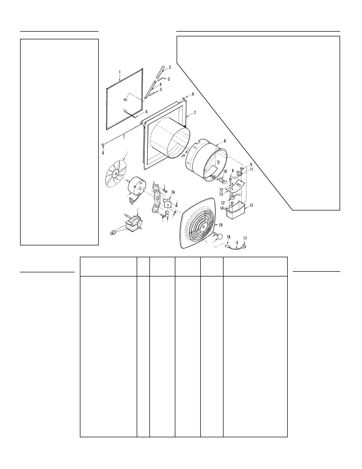
MODEL 506 MODELS 507
PART NO. PART NO.
KEY MODELO 506 MODELO 507 NO.
DESCRIPTION NO. NO. PIEZA NO. PIEZA CODIGO DESCRIPCION
Door Assembly 1 97007002 97007003 1 Conjunto de la compuerta
Door Spring 2 99140147 99140147 2 Muelle de la compuerta
1/8 x 1 Cotter Pin (2 Req.)* 3 99410005 99410005 3 Pasador de chaveta de 1/8 x 1
(se necesitan 2)*
Door Arm 4 98006067 98006067 4 Brazo de la compuerta
Chain 5 99450101 99450101 5 Cadena
Push Nut (2 Req.) 6 99420478 99420478 6 Tuerca de empuje (se necesitan 2)
Outer Housing 7 97007095 97007091 7 Carcasa exterior
Inner Housing 8 97013673 97010379 8 Carcasa interior
#8-18 x 3/8 Serrated Head 9 99170245 99170245 9 Tornillo de cabeza serrada con
Tapping Screw w/Type B Point punta de tipo B No.8-18 x 3/8
(2 Req.)* (se necesitan 2)*
Switch Trigger 10 99390035 99390035 10 Gatillo del interruptor
Receptacle 11 99270982 99270982 11 Enchufe
Switch 12 99030157 99030157 12 Interruptor
Wiring Box Cover 13 98007823 98007823 13 Cubierta de lacaja de conexiones
#10-32 x 1/2 Binder Head 14 99150471 99150471 14 Tornillo de cabeza de presilla con
Tapping Screw w/Type F Point* punta de tipo F No.10-32 x 1/2
Wiring Box 15 98006046 98006046 15 Caja de cables
Grille Bracket 16 98008494 98007819 16 Mensula de réjilla
Pendant 17 99110563 99110563 17 Colgante
Wear Plate 18 98007825 98007825 18 Placa de desgaste (506, 507)
Grille (Polymeric) 19 99110977 99110916 19 Rejilla (Plástico)
Motor Nut (2 Req.) 21 99260425 99260428 21 Tuerca del motor (se necesitan 2)
#8-32 x 1/2 Tapping Screw w/ 22 99150479 99150479 22 Tornillo con punta de tipo U No.
Type 23 Point (2 Req.)* 32 x 1/2 (se necesitan 2)*
1/4-20 U-Type Sheet Metal 23 99420479 99420479 23 Tuerca de lámina metálica tipo
Nut (2 Req.)* U No. 1/4-20 (se necesitan 2)*
Motor Bracket 24 98006066 98007820 24 Soporte del motor
Motor 25 99080596 99080176 25 Motor
Fan Blade 26 99020271 99020165 26 Paleta del ventilador
Door Hinge Rod 27 98006073 98006073 27 Pasador de la bisagra de la
compuerta
#8-15 x 1/4 Serrated Head 28 99150417 99150417 28 Tornillo de cabeza serrada con
Tapping Screw w/Type A Point punta de tipo A No. 8-15 x 1/4
(3 Req.)* (se necesitan 3)*
Grille Knob 29 97011918 97011918 29 Botón de rejilla
Grille Stud 30 99420580 99420585 30 Tornillo de rejilla
PIEZAS DE
SERVICIO
MODELOS 506 y
507
SERVICE
PARTS
MODELS 506 & 507
(506)
(507)
27
26
25
24
22
21
21
23
29
25
22
30
28
GARANTIA BROAN-NUTONE LIMITADA POR UN AÑO
Broan-NuTone garantiza al consumidor comprador original de sus productos que dichos productos
carecerán de defectos en materiales o en mano de obra por un período de un año a partir de la fecha
original de compra. NO EXISTEN OTRAS GARANTIAS, EXPRESAS NI IMPLICITAS, INCLUYENDO,
PERO NO LIMITADAS A, GARANTIAS IMPLICITAS DE COMERCIALIZACION O APTITUD PARA UN
PROPOSITO PARTICULAR.
Durante el período de un año, y a su propio criterio, Broan-NuTone reparará o reemplazará, sin costo
alguno, cualquier producto o pieza que se encuentre defectuosa bajo condiciones normales de
servicio y uso.
ESTA GARANTIA NO SE APLICA A TUBOS Y ARRANCADORES DE LAMPARAS FLUO-
RESCENTES. Esta garantía no cubre (a) mantenimiento y servicio normales ni (b) cualquier
producto o piezas que hayan sido utilizadas de forma errónea, negligente, que hayan tenido
un accidente, o que hayan sido reparadas o mantenidas incorrectamente (por otras com-
pañías que no sean Broan-NuTone), instalación defectuosa, o instalación contraria a las
instrucciones de instalación recomendadas.
La duración de cualquier garantía implícita se limita a un período de un año como
se especifica en la garantía expresa. Algunos estados no permiten limitaciones en
cuanto al tiempo de expiración de una garantía implícita, por lo que la limitación
antes mencionada puede no corresponderle.
LA OBLIGACION DE BROAN-NUTONE DE REPARAR O REEMPLAZAR,
SIGUIENDO EL CRITERIO DE BROAN-NUTONE, DEBERA SER EL
UNICO Y EXCLUSIVO RECURSO LEGAL DEL COMPRADOR BAJO
ESTA GARANTIA. BROAN-NUTONE NO SERA RESPONSABLE
POR DAÑOS ACCIDENTALES, CONSIGUIENTES, O POR DAÑOS
ESPECIALES RESULTANTES O EN CONEXION CON EL USO O
EL RENDIMIENTO DEL PRODUCTO.
Algunos estados no permiten la exclusión o limitación de daños
accidentales o consiguientes, por lo que la limitación antes
mencionada puede no aplicarse a usted.
Esta garantía le proporciona derechos legales específicos,
y usted puede también tener otros derechos, los cuales
varían de estado a estado. Esta garantía reemplaza
todas las garantías anteriores.
Para tener derecho al servicio de garantía,
usted debe (a) notificar a Broan-NuTone en la
dirección que se menciona abajo o al telé-
fono:1-800-637-1453 en los E.E. U.U., (b) dar
el número del modelo y la identificación de
la pieza, y (c) describir la naturaleza de
cualquier defecto en el producto o pieza.
En el momento de solicitar servicio
cubierto por la garantía, usted debe
presentar comprobación de la fecha
original de compra.
Broan, 926 West State Street,
Hartford, WI 53027. EE. UU.
1 / 1

Broan 506 Installation guide

Category
Household fans
Type
Installation guide
This manual is also suitable for

Ask a question and I''ll find the answer in the document

Finding information in a document is now easier with AI

Ask the document

in other languages