
EN
tϰϭϱͲϭϭϰϮͬ&ͬϬϴ͘Ϯϵ͘ϭϴ
FR
PG
21
INSTALLER: LEAVE THIS MANUAL WITH THE APPLIANCE.
CONSUMER: RETAIN THIS MANUAL FOR FUTURE REFERENCE.
NEVER LEAVE CHILDREN OR OTHER AT RISK INDIVIDUALS ALONE WITH THE APPLIANCE.
INSTALLATION AND
OPERATING INSTRUCTIONS
1.41A
Wolf Steel Ltd., 24 Napoleon Rd., Barrie, ON, L4M 0G8 Canada /
103 Miller Drive, Crittenden, Kentucky, USA, 41030
Phone (705)721-1212 • Fax (705)722-6031 • www.napoleonfi replaces.com •[email protected]
SAFETY INFORMATION
!
WARNING
If the information in these instructions are
not followed exactly, a fi re or explosion
may result causing property damage,
personal injury or loss of life.
- Do not store or use gasoline or other fl ammable
vapors and liquids in the vicinity of this or any
other appliance.
$10.00
CERTIFIED UNDER CANADIAN AND AMERICAN NATIONAL STANDARDS: CSA C22.2 No-46 / UL 1278
EFL42S
ELECTRIC FIREPLACE

tϰϭϱͲϭϭϰϮͬ&ͬϬϴ͘Ϯϵ͘ϭϴ
2
EN
NOTE: Changes, other than editorial, are denoted by a vertical line in the margin.
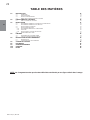
TABLE OF CONTENTS
1.0 INTRODUCTION 3
1.1 DIMENSIONS 4
1.2 LISTING APPROVALS 4
1.3 GENERAL INSTRUCTIONS 5
1.4 UNPACKING AND TESTING APPLIANCE 5
2.0 LOCATING APPLIANCE 6
2.1 GROUNDING APPLIANCE 6
3.0 INSTALLATION 7
3.1 MINIMUM CLEARANCE TO COMBUSTIBLES 8
3.2 MINIMUM MANTEL CLEARANCES 8
3.3 INSTALLING THE APPLIANCE 9
3.4 RECESSING INSTALLATION 10
3.4.1 MINIMUM CLEARANCE TO COMBUSTIBLES 10
3.4.2 FRAMING 10
3.4.3 MOUNTING BRACKET INSTALLATION 11
3.5 HARD WIRING INSTALLATION 12
4.0 FINISHING 13
4.1 GLASS DOOR REMOVAL 13
4.2 CRYSTAL EMBER INSTALLATION 13
5.0 OPERATING INSTRUCTIONS 14
5.1 MAIN POWER SWITCH 14
5.2 OPERATING BY REMOTE CONTROL 14
6.0 WIRING DIAGRAM 15
7.0 REPLACEMENT PARTS 16
8.0 TROUBLESHOOTING 17
9.0 WARRANTY 18
10.0 SERVICE HISTORY 19

tϰϭϱͲϭϭϰϮͬ&ͬϬϴ͘Ϯϵ͘ϭϴ
3
EN
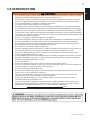
1.0 INTRODUCTION
!
WARNING
3.19
• Do not operate appliance before reading and understanding operating instructions. Failure to operate
appliance according to operating instructions could cause fi re or injury.
• Risk of burns. Power to the appliance should be turned off and the appliance allowed to cool before
servicing. To disconnect power to the appliance, turn controls to off, then remove plug from outlet.
• Do not install damaged, incomplete or substitute components.
• Do not burn wood or other materials in this appliance.
• Any safety screen or guard removed for servicing must be replaced prior to operating the appliance.
• It is imperative that the control compartments, circulating blower and its passageway in the appliance
and are kept clean. The appliance should be inspected before use and at least annually by a qualifi ed
service person. More frequent cleaning may be required due to excessive lint from carpeting, bedding
material, etc. The appliance area must be kept clear and free from combustible materials, gasoline and
other fl ammable vapors and liquids.
• Under no circumstances should this appliance be modifi ed.
• Do not use this appliance if any part has been under water. Immediately call a qualifi ed service technician
to inspect the appliance and to replace any part of the control system which has been under water.
• Do not operate the appliance with the glass door removed, cracked or broken. Replacement of the
glass should be done by a licensed or qualifi ed service person.
• Do not strike or slam shut the appliance glass door.
• Keep the packaging material out of reach of children and dispose of the material in a safe manner. As
with all plastic bags, these are not toys and should be kept away from children and infants.
• Servicing should be done only while the appliance is disconnected from the power supply circuit.
• Always unplug appliance when not in use.
• Do not operate this appliance with a damaged cord or plug after the appliance malfunctions, has been
dropped or damaged in any manner. Return appliance to authorized service facility for examination,
electrical or mechanical adjustment, or repair.
• Do not use outdoors.
• Never locate appliance where it may fall into a bathtub or other water container.
• Do not run cord under carpeting. Do not cover cord with throw rugs, runners, or the like. Arrange cord
away from traffi c area and where it will not be tripped over.
• Connect to properly grounded outlets only.
• Do not insert or allow foreign objects to enter any ventilation or exhaust opening as this may cause an
electric shock or fi re, or damage the appliance.
• To prevent a possible fi re, do not block air intakes or exhaust in any manner. Do not use on soft
surfaces, like a carpet, where openings may become blocked.
• Always plug appliances directly into a wall outlet/receptacle. Never use an extension cord or
relocatable power tap (outlet/power strip).
• Ensure clearances to combustibles are maintained when building a mantel or shelves above the
appliance. Elevated temperatures on the wall or in the air above the appliance can cause melting,
discolouration or damage to decorations, a T.V. or other electronic components.

tϰϭϱͲϭϭϰϮͬ&ͬϬϴ͘Ϯϵ͘ϭϴ
4
EN
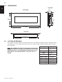
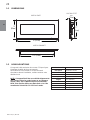
1.1 DIMENSIONS
1.2 LISTING APPROVALS
This appliance has been tested in accordance with the CSA Standards for fi xed and location-dedicated electric
room appliances in the United States and Canada. If you need assistance during installation, please contact
your local dealer.
NOTE: This appliance must be electrically wired and grounded
in accordance with local codes or, in the absence of local codes,
with National Electric Code ANSI/NFPA 70-latest edition in the
United States or the Canadian Electric Code, CSA C22.1 in
Canada.
Model Number EFL42S
Description Wall-Mount
Appliance
Voltage 120V AC
Watts MAX 15W
Amps 15 AMP Grounded
Circuit
Appliance Width 42" (1067mm)
Appliance Height 19" (483mm)
Appliance Depth 4 3/4" (121mm)
Net Weight 20 Kg (44lbs)
Gross Weight 26 Kg (57lbs)
FRONT VIEW
TOP VIEW
SIDE VIEW
42" [1067mm]
19"
[483mm]
17"
[432mm]
4 3/4"
[121mm]
35 1/2" [902mm]

tϰϭϱͲϭϭϰϮͬ&ͬϬϴ͘Ϯϵ͘ϭϴ
5
EN
1.3 GENERAL INSTRUCTIONS
4.8B
A. Prior to plugging your appliance into an electrical outlet, verify that the house circuit breakers for the
outlet are on.
B. The appliance may emit a slight, harmless odour when fi rst used. This odour is normal and it is caused
by the initial heating of internal appliance elements and will not occur again.
C. If your appliance does not emit heat, consult the operation section of this manual for further
information.
D. Use with a CSA or UL certifi ed surge protector.
E. Do not route the power cord directly underneath the appliance.
This electric appliance meets the construction and safety standards of H.U.D. for application in manufactured
homes when installed according to these instructions.
!
WARNING
READ THESE INSTRUCTIONS COMPLETELY BEFORE BEGINNING INSTALLATION. FAILURE TO
FOLLOW THEM COULD CAUSE AN APPLIANCE MALFUNCTION RESULTING IN SERIOUS INJURY
AND/OR PROPERTY DAMAGE.
ALL ELECTRIC APPLIANCES HAVE HOT AND ARCING OR SPARKING PARTS INSIDE. DO NOT USE
IT IN AREAS WHERE GASOLINE, PAINT OR FLAMMABLE LIQUIDS ARE PRESENT.
THIS ELECTRIC APPLIANCE IS TESTED AND LISTED FOR USE ONLY WITH THE OPTIONAL
ACCESSORIES LISTED IN THESE INSTRUCTIONS. USE OF OPTIONAL ACCESSORIES NOT
SPECIFICALLY TESTED FOR THIS ELECTRIC APPLIANCE COULD VOID THE WARRANTY AND/OR
RESULT IN A SAFETY HAZARD.
DO NOT OPEN. RISK OF ELECTRIC SHOCK. NO USER-SERVICEABLE PARTS INSIDE.
DO NOT USE DAMAGED ELECTRICAL CORDS.
SERVICING SHOULD BE DONE ONLY WHILE THE APPLIANCE IS DISCONNECTED FROM THE
POWER SUPPLY CIRCUIT.
TO PREVENT ELECTRIC SHOCK MATCH THE WIDE BLADE OF PLUG TO WIDE SLOT OF
RECEPTACLE AND FULLY INSERT.
As with most electronic devices, your new electric fireplace has been designed to operate at
temperatures between 5°C (41°F) and 35° C (95°F). During the colder winter months, allow the fi replace
to reach room temperature before turning it on.
1.4 UNPACKING AND TESTING APPLIANCE
Carefully remove the appliance from the box. Prior to installing the appliance, test to make sure the appliance
operates properly by plugging the power supply cord into a conveniently located 120 Volt, 15 Amp grounded
outlet.

tϰϭϱͲϭϭϰϮͬ&ͬϬϴ͘Ϯϵ͘ϭϴ
6
EN
!
WARNING
2.0 LOCATING APPLIANCE
2.1 GROUNDING APPLIANCE
DUE TO HIGH TEMPERATURES, THIS ELECTRIC APPLIANCE SHOULD BE LOCATED OUT OF
TRAFFIC. KEEP COMBUSTIBLE MATERIALS SUCH AS FURNITURE, PILLOWS, BEDDING, PAPERS,
CLOTHES AND CURTAINS AT LEAST 36" FROM THE FRONT OF THE APPLIANCE.
NEVER LOCATE THIS ELECTRIC APPLIANCE WHERE IT MAY FALL INTO A BATHTUB OR OTHER
WATER CONTAINER.
WEAR SAFETY GLOVES AND SAFETY GLASSES FOR PROTECTION DURING INSTALLATION AND
MAINTENANCE.
TO PREVENT CONTACT WITH SAGGING OR LOOSE INSULATION, THE ELECTRIC APPLIANCE
MUST NOT BE INSTALLED AGAINST VAPOR BARRIER OR EXPOSED INSULATION. LOCALIZED
OVERHEATING COULD OCCUR AND A FIRE COULD RESULT.
DO NOT EXPOSE THE ELECTRIC APPLIANCE TO THE ELEMENTS (SUCH AS RAIN, ETC.)
96.1
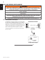
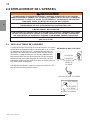
GROUNDING METHODS
METAL SCREW
(A)
NOT ALLOWED IN CANADA
GROUNDING
MEANS
ADAPTER
GROUNDING PIN
COVER OF
GROUNDED
OUTLET BOX
(C)
(B)
This appliance is
f
or use on 120 Volts. The cord has a plug
as shown in (A). An adapter as shown in (C) is available
for connecting three-blade grounding type plugs to two-slot
receptacles. The green grounding lug extending from the
adapter must be connected to a permanent ground such as
a properly grounded outlet box. The adapter should not be
used if a three-slot grounded receptacle is available.
To disconnect appliance, turn controls to off, then remove
plug from outlet.

tϰϭϱͲϭϭϰϮͬ&ͬϬϴ͘Ϯϵ͘ϭϴ
7
EN
3.0 INSTALLATION
Your EFL42S is a wall-mounted appliance. Select a suitable location that is not susceptible to moisture and is
away from drapes, furniture and high traffi c areas. NOTE: Follow all National and local electrical codes.
!
WARNING
RISK OF FIRE! THE POWER CORD MUST NOT BE PINCHED AGAINST A SHARP EDGE. SECURE CORD TO AVOID
TRIPPING OR SNAGGING TO REDUCE THE RISK OF FIRE, ELECTRIC SHOCK OR PERSONAL INJURY. DO NOT RUN
CORD UNDER CARPETING. DO NOT COVER CORD WITH THROW RUGS, RUNNERS OR THE LIKE. ARRANGE CORD
AWAY FROM TRAFFIC AREAS AND WHERE IT WILL NOT BE TRIPPED OVER.
RISK OF FIRE! TO PREVENT A POSSIBLE FIRE, DO NOT BLOCK AIR INTAKE OR EXHAUST IN ANY MANNER. DO NOT
USE ON SOFT SURFACES WHERE OPENINGS MAY BECOME BLOCKED.
RISK OF FIRE! DO NOT BLOW OR PLACE INSULATION AGAINST THE APPLIANCE.
THIS ELECTRIC APPLIANCE IS TESTED AND LISTED FOR USE ONLY WITH THE APPROVED OPTIONAL ACCESSORIES.
USE OF OPTIONAL ACCESSORIES NOT SPECIFICALLY TESTED FOR THIS ELECTRIC APPLIANCE COULD VOID THE
WARRANTY AND/OR RESULT IN A SAFETY HAZARD.
IF THE INFORMATION IN THESE INSTRUCTIONS IS NOT FOLLOWED EXACTLY, A FIRE OR EXPLOSION MAY RESULT
CAUSING PROPERTY DAMAGE, PERSONAL INJURY OR DEATH. DO NOT STORE OR USE GASOLINE OR OTHER
FLAMMABLE VAPORS IN THE VICINITY OF THIS OR ANY OTHER APPLIANCE.
THIS APPLIANCE IS HEAVY. IT IS HIGHLY RECOMMENDED THAT TWO PEOPLE INSTALL THIS APPLIANCE.
68.6

tϰϭϱͲϭϭϰϮͬ&ͬϬϴ͘Ϯϵ͘ϭϴ
8
EN
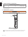
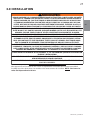
3.1 MINIMUM CLEARANCE TO COMBUSTIBLES
Measurements are taken from the glass front.
Bottom 0" Top 8" (203mm) to mantel
Sides 0" Top 8" (203mm) to ceiling
Back 0"
Side View
Mantel
Floor
Wall
8” (203.2mm)
!
WARNING
WHEN USING PAINT OR LACQUER TO FINISH THE MANTEL, THE PAINT OR LACQUER MUST BE
HEAT RESISTANT TO PREVENT DISCOLOURATION.
3.2 MINIMUM MANTEL CLEARANCES
NOTE: The power switch is located on the lower right hand side of the appliance. Always ensure that access to
this switch remains available.
NOTE: THE 8" (203mm) CLEARANCE TO THE MANTEL/CEILING IS RECOMMENDED FOR SERVICE (GLASS
REMOVAL). CLEARANCES MAY BE REDUCED TO ZERO, WITHOUT CONCERN FOR COMBUSTIBLES.

tϰϭϱͲϭϭϰϮͬ&ͬϬϴ͘Ϯϵ͘ϭϴ
9
EN
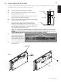
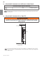
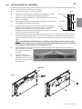
3.3 INSTALLING THE APPLIANCE
Due to the many different materials used on different walls, it is highly recommended that you consult your
local builder before you install this appliance on the wall.
A. Select a location that is not prone to moisture.
B. Have two people hold the appliance against the wall to
determine the fi nal location.
C. With the appliance in position and level measure from the
fl oor to the top back edge as illustrated.
D. Remove the bracket from the back of the unit by removing
the two screws, refer to Figure 1.
E. Mark out location, then mount the bracket onto the
wall using the 8 supplied screws. Ensure the top slots
measurement from the fl oor is 1 1/4” (32mm) lower then the
top back edge measured earlier. This bracket MUST have
the hooks facing upward and be level.
NOTE: It is strongly recommended that the mounting bracket be screwed into the wall studs
where possible. If the wall studs cannot be used, ensure that the supplied plastic anchors are
used to affi x the bracket to the wall and the bracket is adequately secured.
F. With the wall mounting
bracket installed have two
people lift the appliance up
and insert the two hooks on
the bracket into the two slots
on the back of the appliance.
G. Check the appliance for stability ensuring that the bracket will not pull free from the wall, causing the
appliance to fall.
SIDE VIEW
BODY
FLOOR
GLASS FRONT
19"
483mm
HOOK
SCREWS
HOOK
BRACKET
FIG. 1

tϰϭϱͲϭϭϰϮͬ&ͬϬϴ͘Ϯϵ͘ϭϴ
10
EN
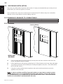
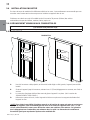
Measurements are taken from the body.
Sides, back and top 0"
A. Once the rough opening has been prepared, and the power has been routed to the left side of the
recess, the appliance may be installed.
B. Lift the appliance up to the opening, maintaining the 1" (25mm) clearance to the top, sides and bottom.
C. The electrical connection must be made prior to sliding the appliance into place. (See "HARD WIRE
INSTALLATION" section.)
D. Using the 4 screws provided, level the appliance and use the retaining brackets to secure the
appliance to the to the wall.
NOTE: In order to avoid the possibility of exposed insulation or vapour barrier coming in contact
with the appliance body, it is recommended that the walls of the appliance enclosure be "fi nished"
(ie. drywall/sheetrock), as you would fi nish any other outside wall of a home. This will ensure that
clearance to combustibles is maintained within the cavity.
36 1/2”
17.5” (445mm)
6”
(
152mm)
6.5” (16
5
mm)
(927
m
m)
17.5” (445mm)
(927
m
m)
36
1/2”
Finishing Material
Due to the many different fi nish materials used on walls, it is highly recommended that you consult your local
builder before you install this appliance in the wall.
Select a location that is not prone to moisture and is located at least 36" (914mm) away from combustible
materials such as curtain drapes, furniture, bedding, paper etc.
3.4 RECESSING INSTALLATION
3.4.1 MINIMUM CLEARANCE TO COMBUSTIBLES
3.4.2 FRAMING
(NON-LOAD
BEARING)

tϰϭϱͲϭϭϰϮͬ&ͬϬϴ͘Ϯϵ͘ϭϴ
11
EN
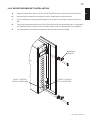
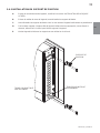
3.4.3 MOUNTING BRACKET INSTALLATION
A. Remove the glass front, refer to "GLASS FRONT INSTALLATION" section for removal instructions.
B. Remove the glass media from the appliance prior to installing the mounting brackets.
C. Prior to installing the mounting brackets determine if you will be recessing the appliance partially or
fully.
D. Secure two mounting brackets to each side of the appliance use the appropriate holes, as illustrated in
the illustration below, using the 8 screws provided to secure the mounting brackets to the appliance.
E. Level the appliance and secure the brackets to wall using the 4 screws provided.
HOLES TO INSTALL
PARTIALLY RECESSED
MOUNTING
BRACKET
HOLES TO INSTALL
FULLY RECESSED

tϰϭϱͲϭϭϰϮͬ&ͬϬϴ͘Ϯϵ͘ϭϴ
12
EN
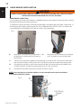
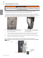
3.5 HARD WIRING INSTALLATION
HARD WIRING CONNECTION
If it is necessary to hard wire this appliance, a qualifi ed electrician must remove the cord connection, and wire
the appliance directly to the house hold wiring.
This appliance must be electrically connected and grounded in accordance with local codes, if hard wired. In
the absence of local codes, use the current CSA C22.1 CANADIAN ELECTRICAL CODE in Canada or the
current ANSI/NFPA 70 NATIONAL ELECTRICAL CODE in the United States.
!
WARNING
TURN OFF THE APPLIANCE COMPLETELY AND LET COOL BEFORE SERVICING. ONLY A QUALIFIED SERVICE
PERSON SHOULD SERVICE AND REPAIR THIS ELECTRIC APPLIANCE.
A. Remove the cover plate from the right side of
the appliance by removing the four screws, as
shown above.
COVER PLATE
B. Remove the wire connectors from the power
cord.
The power cord may be discarded.
NOTE: Leave enough wire so that the appliance can be removed from the enclosure without
disconnecting the power supply.
C. Take the new cover plate, supplied in the manual bag. Punch out the 7/8" (22.2mm) hole and install a
box connector through, into the junction box. Snap the box connector clamp onto the supply wires.
D. Using the wire connectors, connect the common blue wires (B) and white wires (W) together, then
hot black wires (B1) and then the ground green wires (G), refer to Figure 3.
E. Reinstall the cover plate using the four screws, as shown in step A.
Fig. 1
Fig. 2
Fig. 3
7/8" (22.2mm)
Diameter
G
B1
B
W

tϰϭϱͲϭϭϰϮͬ&ͬϬϴ͘Ϯϵ͘ϭϴ
13
EN
4.0 FINISHING
!
WARNING
POWER SUPPLY SERVICE MUST BE COMPLETED PRIOR TO FINISHING TO AVOID
RECONSTRUCTION.
AIR OPENINGS CANNOT BE COVERED IN ANY CIRCUMSTANCES.
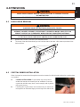
4.1 GLASS DOOR REMOVAL
A. Remove the 4 screws, as shown in the illustration below.
B. Tilt the top of the door forward until you can hold the sides of the door. Lift the door up and out of the
bottom retainer.
!
WARNING
GLASS MAY BE HOT, DO NOT TOUCH GLASS UNTIL COOLED.
FACING AND/OR FINISHING MATERIALS MUST NOT INTERFERE WITH AIR FLOW THROUGH AIR
OPENINGS, LOUVRES OPENINGS, OPERATION OF LOUVRES OR DOORS OR ACCESS FOR
SERVICE. OBSERVE ALL CLEARANCES WHEN APPLYING COMBUSTIBLE MATERIALS.
BEFORE DOOR IS REMOVED TURN THE APPLIANCE OFF AND WAIT UNTIL APPLIANCE IS COOL
TO THE TOUCH. DOORS ARE HEAVY AND FRAGILE SO HANDLE WITH CARE.
4.2 CRYSTAL EMBER INSTALLATION
Glass front must be removed and the appliance must be mounted in its fi nal location before the crystal embers
are installed.
A. CLEAN CRYSTAL MEDIA: Crystal media may have a fi ne oil
residue that needs to be cleaned prior to installation. Clean the
crystal with mild dish soap, drain, rinse thoroughly and dry before
placing into the tray.
B. Carefully place crystal embers into the bottom tray on the front of
the appliance as illustrated. Apply an even layer from side to side.

tϰϭϱͲϭϭϰϮͬ&ͬϬϴ͘Ϯϵ͘ϭϴ
14
EN
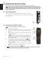
5.0 OPERATING INSTRUCTIONS
Once the appliance has been plugged into a grounded electrical outlet, it is ready to operate.
NOTE: Ensure the house circuit breakers for the power supply are turned on. In the event of a power
failure, when the main power switch of the appliance is in the "I" ON position and the hand held remote
control is in the OFF position, the fl ame generation lights will come back on at the high setting, when
the power supply returns.
The Main Power Switch is located on the bottom of the appliance as illustrated.
The "|" indicates ON and "O" indicates OFF. Push the "|" switch to turn on the appliance
and the
fl ame effect.
5.1 MAIN POWER SWITCH
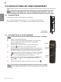
5.2 OPERATING BY REMOTE CONTROL
POWER
SWITCH
NOTE: Make certain new batteries are installed correctly.
A. Plug in your electric appliance.
B. Make certain the appliance’s Main Power Switch is at the ON position!
The remote control will NOT work if the Main Power Switch is at the OFF
position.
C. When operating the remote control, it must be directed towards the front
center of the appliance.
D. The
button at the top left of the remote can be used to power up or
down the appliance (the main power switch on the appliance must be in
the ON position for the remote to operate). Pressing this button activates
the power to the appliance.
E. To activate fl ame, press the "FLAME POWER BUTTON"
button
and then to adjust the yellow fl ame height press the “
+5” or “ -5”
"YELLOW FLAME BUTTONS on the top set of controls. There are fi ve
levels of fl ame effects.
F. To adjust the blue fl ame press the "BLUE FLAME BUTTONS" “
+5” or
“
-5” buttons. There are fi ve levels of fl ame effects.
G. To turn off the appliance, press the button
once.
FLAME
POWER
BUTTON
BLUE
FLAME
BUTTONS
YELLOW
FLAME
BUTTONS
NOTE: This remote control must remain within 8 meters or 26 feet of the appliance to be effective
and this range may be reduced as the battery power is depleted.

tϰϭϱͲϭϭϰϮͬ&ͬϬϴ͘Ϯϵ͘ϭϴ
15
EN
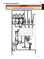
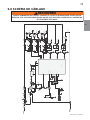
6.0 WIRING DIAGRAM
!
WARNING
TURN OFF THE APPLIANCE COMPLETELY AND LET COOL BEFORE SERVICING. ONLY A QUALIFIED SERVICE
PERSON SHOULD SERVICE AND REPAIR THIS ELECTRIC APPLIANCE.
F1
FUSE2
T2
8050
T1
80 50
T3
8050
RELAY-H2
RELAY-H1
RELAY -MO TOR
R6
10K
S1
P-SW
23 0V,1 20V /1 2V
TRANS1
Vi n
1
GND
2
Vout
3
78 05IC1
MOTOR
C1
470U/35V
C3
1KU /16V
C2
C4
104
1
2
3
4
1N 400 7 *4
D1~D4
t
25*C,5K
TH ERMI STOR
1
2
3
4
5
6
SIP2
2. 4*7
R7
51 0
R3 510
R5
51 0
R2
510
R4
510
1
2
TEMP
2. 4*2
L1
N
H2 PH-2
6. 3*0.8
6. 3*0.8
MOTOR
H1+FAN
6. 3*0.8
P-NI
6. 3*0.8
D5
1N 4007
D6
1N 4007
D7
1N 400 7
VSSVD D
20 10
P0.1
P4.1/AIN1
P4.2/AIN2
P0.4
P5.3
P5.2
P0.5
P0.6
P0.7
8
P5.0
P5.1
SN8P2722
2
15
16
5
12
11
3
9
10
PH-4
6. 3*0.8
N
P-L
6. 3*0.8
TEMP_BRK
PH-7
6. 3*0.8
PH-6
6. 3*0.5 8
PTC
F2
t130
+5V
+5V
R14
10K
C7
104
C9
104
R15
10 K
LED1LED0
T8
SS8050
R?
180
DS?
LED3
DS?
LED2
R?
180
1
2
LED-HY
2. 4*2
1
2
FIRE-B
2. 4*2
LED6LED5
T7
SS8050
100
LED8LED7
R?
100
1
2
LED-HB
2. 4*2
1
2
FIRE-Y
2. 4*2
+12V
+12V
+12V
+12V
6
P0.2
7
C6
C8
5v
25V 47uF
10 4
HS00 38
BUZ1
D9
40 07
T4
SS 8050
R8
510
+5V
R9
1K
R20
10 0/0.5W
R1
51 0
LED6LED5
T6
SS8050
18 0
LED8LED7
R?
10 0
1
2
LED-M
2. 4*2
1
2
LAMP
2. 4*2
+12V
+12V
+12V

tϰϭϱͲϭϭϰϮͬ&ͬϬϴ͘Ϯϵ͘ϭϴ
16
EN
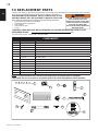
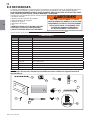
Contact your dealer or the factory for questions concerning prices and policies on replacement parts. Normally
all parts can be ordered through your Authorized dealer / distributor.
FOR WARRANTY REPLACEMENT PARTS, A PHOTOCOPY OF THE
ORIGINAL INVOICE WILL BE REQUIRED TO HONOUR THE CLAIM.
When ordering replacement parts always give the following information:
• Model & Serial Number of appliance
• Installation date of appliance
• Part number
• Description of part
• Finish
* IDENTIFIES ITEMS WHICH ARE NOT ILLUSTRATED. FOR FURTHER INFORMATION, CONTACT YOUR
AUTHORIZED DEALER.
41.1
FAILURE TO POSITION THE PARTS
IN ACCORDANCE WITH THIS
MANUAL OR FAILURE TO USE ONLY
PARTS SPECIFICALLY APPROVED
WITH THIS APPLIANCE MAY
RESULT IN PROPERTY DAMAGE OR
PERSONAL INJURY.
!
WARNING
For after sales service, please call 1-866-820-8686
NOTE: Care must be taken when removing and disposing of any broken glass or damaged
components. Be sure to vacuum up any broken glass from inside the appliance before operation.
7.0 REPLACEMENT PARTS
7
4
1
5
2
3
8
12
9
13
BLUE LIGHT
+5 MAX-5 OFF
TEMPLOWHIGH
FLAME
+5 MAX-5 OFF
HEAT
6
14
COMPONENTS
REF NO. PART NO. DESCRIPTION
1 W405-0008 LED CIRCUIT BOARD FOR EMBER BED
2 W190-0050 CIRCUIT BOARD
3 W660-0128 SWITCH (RK1-11)
4 W190-0051 REMOTE CONTROL
5 W300-0171 FRONT GLASS (42" x 19") (1067mm x 483mm)
6 W300-0156 MIRROR GLASS
7 W707-0016 TRANSFORMER
8 W010-2918 DRUM ASSEMBLY
9 W660-0129 REMOTE RECEIVER
10* W300-0178 CRYSTAL (0.54kg (1.2lbs)
11* W435-0055 120V 30/36RPM MOTOR
12 W080-1282 WALL MOUNT BRACKET
13 W285-0007 FUSE, 0.5A
14 W020-0879 HARDWARE KIT

tϰϭϱͲϭϭϰϮͬ&ͬϬϴ͘Ϯϵ͘ϭϴ
17
EN
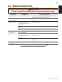
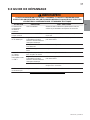
8.0 TROUBLESHOOTING
SYMPTOM PROBLEM TEST SOLUTION
Dim or no fl ame Drum LED’s are burnt out Inspect the LED’s inside the fl ame generation cylinder drum
(W010-2918) and replace them if necessary
Ember bed is not
glowing or dimming
Ember LED’s are burnt out Inspect the ember bed LED’s (W405-0008) and replace them if
necessary
Appliance turns off
and will not turn on
Appliance has overheated
and safety device has
caused the thermal switch to
disconnect
Unplug the appliance, allow appliance to cool for 15 minutes,
then plug it back in
House circuit breaker has
tripped
Appliance’s fuse has blown
Reset house circuit breaker
Replace the fuse
Appliance will not
come on when
switch is fl ipped to
ON
Appliance is not plugged into
an electrical outlet
Check plug and plug it in
Appliance has overheated
and safety device has
caused the thermal switch to
disconnect
Circuit board is burnt out
Unplug the appliance, allow appliance to cool for 15 minutes,
then plug it back in
Inspect the circuit board (W190-0050) and replace it if
necessary
Remote control
does not work
Low batteries Replace batteries in remote control
!
WARNING
TURN OFF THE APPLIANCE COMPLETELY AND LET COOL BEFORE SERVICING. ONLY A
QUALIFIED SERVICE PERSON SHOULD SERVICE AND REPAIR THIS ELECTRIC APPLIANCE.
42.30

tϰϭϱͲϭϭϰϮͬ&ͬϬϴ͘Ϯϵ͘ϭϴ
18
EN
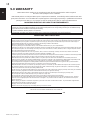
9.0 WARRANTY
NAPOLEON warrants its products against manufacturing defects to the original purchaser only. Registering your warranty is not necessary.
Simply provide your proof of purchase along with the model and serial number to make a warranty claim. NAPOLEON reserves the right to have
its representative inspect any product or part thereof prior to honouring any warranty claim. Provided that the purchase was made through an
authorized NAPOLEON dealer your appliance is subject to the following conditions and limitations:
Warranty coverage begins on the date of original installation.
This factory warranty is non-transferable and may not be extended whatsoever by any of our representatives.
Installation must be done in accordance with the installation instructions included with the product and all local and national building and fi re codes.
This limited warranty does not cover damages caused by misuse, lack of maintenance, accident, alterations, abuse or neglect and parts installed
from other manufacturers will nullify this warranty.
This limited warranty further does not cover any scratches, dents, corrosion or discoloring caused by excessive heat, abrasive and chemical
cleaners nor chipping on porcelain enamel parts, mechanical breakage of PHAZER™ logs.
In the fi rst year only, this warranty extends to the repair or replacement of warranted parts which are defective in material or workmanship provided
that the product has been operated in accordance with the operation instructions and under normal conditions.
NAPOLEON will not be responsible for installation, labour or any other expenses related to the reinstallation of a warranted part and such
expenses are not covered by this warranty. Notwithstanding any provisions contained in the Limited Warranty, NAPOLEON’s responsibility under
this warranty is defi ned as above and it shall not in any event extend to any incidental, consequential or indirect damages.
This warranty defi nes the obligations and liability of NAPOLEON with respect to the NAPOLEON electric appliance and any other warranties
expressed or implied with respect to this product, its components or accessories are excluded.
NAPOLEON neither assumes, nor authorizes any third party to assume, on its behalf, any other liabilities with respect to the sale of this product.
Any damages to appliance, brass trim or other component due to water, weather damage, long periods of dampness, condensation, damaging
chemicals or cleaners will not be the responsibility of NAPOLEON.
The bill of sale or copy will be required together with a serial number and a model number when making any warranty claims from your authorized
dealer. The warranty registration card must be returned within fourteen days to register the warranty.
NAPOLEON reserves the right to have its representative inspect any product or part thereof prior to honouring any warranty claim.
All parts replaced under the Limited Warranty Policy are subject to a single claim.
All parts replaced under the warranty will be covered for a period of 90 days from the date of their installation.
The manufacturer may require that defective parts or products be returned or that digital pictures be provided to support the claim. Returned
products are to be shipped prepaid to the manufacturer for investigation. If a product is found to be defective, the manufacturer will repair or
replace such defect.
Before shipping your appliance or defective components, your dealer must obtain an authorization number. Any merchandise shipped without
authorization will be refused and returned to sender.
Shipping costs are not covered under this warranty.
Additional service fees may apply if you are seeking warranty service from a dealer.
2.5C
NAPOLEON electric appliances are manufactured under the strict Standard of the world recognized
ISO 9001 : 2008 Quality Assurance Certifi cate.
NAPOLEON products are designed with superior components and materials, assembled by trained craftsmen who take
great pride in their work. Once assembled the complete appliance is thoroughly inspected by a qualifi ed technician before
packing to ensure that you , the customer, receive the quality product that you expect from NAPOLEON.
Electrical components and wearable parts such as fan/heater, motors, switches, nylon bearing components and remote
controls are covered and NAPOLEON will provide replacement parts free of charge during the fi rst year of limited warranty.
Light bulbs and fuses are NOT covered by the warranty.
Any labour related to warranty repair is not covered.
* Construction of models vary. Warranty applies only to components included with your specifi c appliance.
NAPOLEON ELECTRIC APPLIANCE LIMITED WARRANTY
CONDITIONS AND LIMITATIONS
ALL SPECIFICATIONS AND DESIGNS ARE SUBJECT TO CHANGE WITHOUT PRIOR NOTICE DUE TO ON-GOING PRODUCT IMPROVEMENTS.
NAPOLEON IS A REGISTERED TRADEMARK OF WOLF STEEL LTD.

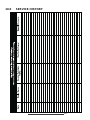
10.0 SERVICE HISTORY
43.1

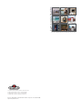
Other Napoleon
®
Products
'JSFQMBDF*OTFSUTt$IBSDPBM(SJMMT
t(BT'JSFQMBDFTt8BUFSGBMMTt8PPE4UPWFT
)FBUJOH$PPMJOHt&MFDUSJD'JSFQMBDFTt0VUEPPS'JSFQMBDFTt(BT(SJMMT
'JSFQMBDFT)FBUJOH$PPMJOHDBMMt(SJMMTDBMM
napoleonproducts.com
/BQPMFPO3PBE#BSSJF0OUBSJP$BOBEB-.(
#BZWJFX%SJWF#BSSJF0OUBSJP$BOBEB-/:
.JMMFS%SJWF$SJUUFOEFO,FOUVDLZ64"
5SBOT$BOBEB)JHIXBZ.POUSFBM2VFCFD$BOBEB)5"
Page is loading ...
Page is loading ...
Page is loading ...
Page is loading ...
Page is loading ...
Page is loading ...
Page is loading ...
Page is loading ...
Page is loading ...
Page is loading ...
Page is loading ...
Page is loading ...
Page is loading ...
Page is loading ...
Page is loading ...
Page is loading ...
Page is loading ...
Page is loading ...
Page is loading ...
Page is loading ...
-
 1
1
-
 2
2
-
 3
3
-
 4
4
-
 5
5
-
 6
6
-
 7
7
-
 8
8
-
 9
9
-
 10
10
-
 11
11
-
 12
12
-
 13
13
-
 14
14
-
 15
15
-
 16
16
-
 17
17
-
 18
18
-
 19
19
-
 20
20
-
 21
21
-
 22
22
-
 23
23
-
 24
24
-
 25
25
-
 26
26
-
 27
27
-
 28
28
-
 29
29
-
 30
30
-
 31
31
-
 32
32
-
 33
33
-
 34
34
-
 35
35
-
 36
36
-
 37
37
-
 38
38
-
 39
39
-
 40
40


Ask a question and I''ll find the answer in the document
Finding information in a document is now easier with AI
in other languages
- français: NAPOLEON EFL42S Manuel utilisateur
Related papers
-
NAPOLEON NEFE29-1616E User manual
-
-
-
-
-
-
-
-
-
Other documents
-
Ryvyr M-PURUS-24DW Installation guide
-
Nady Systems W1KU User manual
-
Continental Fireplaces CEFL42FH Owner's manual
-
-
-
Superior Fireplaces ERC4000 Operating instructions
-
-
-
-
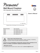 Paramount EF-WM373 MO Installation guide
