Page is loading ...

1
KIT CONTENTS
The Alarm System should contain the following
components.
1 x Control Panel
1 x Wirefree Motion Sensor
1 x Wirefree Door/Window Contact Detector
1 x Remote Controller
Also included:
4 x 1.5V LR20 size battery
1 x 2m telephone connection lead
Installation & Operating Manual
Fixing pack
Control Panel
4 x 1.5V LR20 size D-cell battery or
9V DC adapter (option)
Motion Sensor
3 x 1.5V AA size battery (option)
Door/Window
Contact Detector
3 x 1.5V AAA size battery (option)
Remote Controller
1 x 3V CR2032 Lithium
IMPORTANT
Please check all items as mentioned above are
included in the package.
SC401 Control Panel
SP831 Wirefree Motion Sensor
SM831 Wirefree Door/Window Contact Detector
SR401 Remote Controller

2
INTRODUCTION AND OVERVIEW
ALARM DURATION
This is the length of time that the alarm will sound for,
following an intrusion. Alarm duration can be set for
either 1 or 3 minutes via settings in the Control Panel.
(If accidentally triggered, the alarm can be stopped at
any time using the Remote Controller).
SYSTEM ARMING
The system has a full ‘Arm’ and a ‘Part-Arm’ mode.
ARM will ‘Arm’ all zones while the ‘Part-Arm’ mode will
only arm zone 1.
For example:
The system could be configured such that during night
time, ‘Part-Arm’ would arm only zone protecting the
lower floor and outbuildings leaving the upper floor free
for movement without triggering the alarm.
When the property is left un-occupied, the full ‘Arm’
mode will arm all zones to protect the entire property,
(i.e. upper and lower floors and outbuildings).
ENTRY/EXIT DELAY
When the system is armed, no alarm signal from any
detector will be able to initiate an alarm until the
Exit-Delay has expired. This enables the system to be
armed from within the property and allows time for the
user to exit the property without triggering an alarm.
The system Exit-Delay is fixed at 15 seconds. The
system won’t be armed until 15 seconds Exit-Delay is
expired. If a detector on a zone is triggered, then an
alarm condition will occur.
When the system is part-armed, Zone 1 will be armed
instantly. If a detector on Zone 1 is triggered, an alarm
condition will not occur until the Entry-Delay period has
expired. This allows time for the user to re-enter the
property and disarm the system before an alarm
condition occurs.
The system Entry-Delay can be chosen either 15
seconds or disabled. If a detector on Zone 1 is
triggered, a full alarm condition will not be initiated until
15 seconds Entry-Delay is expired.
BATTERY
The Control Panel is powered by 4 1.5V LR20 size
D-cell battery which under normal conditions will have
typical life in excess of 2 years. Alternatively a 9V
power adapter (option) can be adopted.
SYSTEM ZONING
The detector(s) may be set to operate on either Zone 1,
Zone 2 or panic. For ease of alarm verification it is
recommended that the Zones are arranged logically,
(eg. downstairs detectors on Zone 1 and upstairs
detectors on Zone 2, or Motion sensors on Zone 1 and
Door/Window Contact detectors on Zone 2). If the
detector is learned the ID code by the Control Panel on
Zone 1, then the detector is set on Zone 1. If the
detector is learned the ID code by the Control Panel on
panic zone, activation of detector at any time will
immediately initiate a full alarm condition of which
status will be indicated on the panic zone.
If the tamper switch of detectors set in zone 1 or 2 or
the panic switch of remote controller have been
triggered, activation of detector at any time will
immediately initiate a full alarm condition of which
status will be indicated on the panic zone.
TAMPER PROTECTION
All system devices (except the Remote Controllers)
incorporate Tamper protection features to protect
against unauthorized attempts to interfere with the
device. Any attempt to remove any device (except the
Remote Controller) or to remove Control Panel from the
wall will initiate an alarm condition (unless the system is
in Test or ID code learning modes), even if the system
is Disarmed.
JAMMING DETECTION
In order to detect any attempts to illegally jam the radio
channel used by your alarm system, a special jamming
detection function is incorporated into the Control Panel.
If this feature is enabled, and the radio channel is
jammed continuously for 30 seconds, when the system
is armed, a full alarm condition will occur.
If the radio channel is jammed continuously for 30
seconds, when the system is part-armed, a full alarm
condition will occur.
The Jamming Detection circuit is designed to scan for
jamming signals. However, it is possible that it may
detect other local radio interference operating legally or
illegally on the same frequency. If it is planned to
operate the jamming detection feature we recommend
that the system is monitored for false jamming alarms
for at least 2 weeks prior to leaving the Jamming
Detection function permanently enabled.

3
LEARNING ID CODE
In order to prevent any unauthorized attempt to operate
or disarm your system, you must configure your system
to accept radio signals only from your own system
devices. All detectors and Remote Controllers have
their unique ID code, the Control Panel must learn
their codes individually for the system to operate
correctly.
For the Motion and Door/Window Contact Detectors,
simply pressing the tamper switch located adjacent to
the PCB will emit the ID code to the Control Panel
instantly with the Control Panel being set at the ID code
learning mode. For the Remote Controller, pressing any
button on the Remote Controller will emit the ID code to
the Control Panel instantly with the Control Panel being
set at the ID code learning mode.

4
PLANNING AND EXTENDING YOUR
WIREFREE ALARM SYSTEM
The following example below shows a typical property
incorporating the suggested positions for the Control
Panel, Motion and Door/Window Contact Detectors for
optimum security. Use this as a guide for your
installation in conjunction with the recommendations
contained in this manual for planning your intruder
alarm system.
Before attempting to install your Alarm System it is
important to study your security requirements and plan
your installation.
The alarm system may be extended to provide even
greater protection by fitting additional Motion Sensors
and Door/Window Contact Detectors as required.

5
CONTROL PANEL
CHOOSING THE DETECTOR TYPE
Zone 1 provides standard intruder monitoring with
normal ARM and PART-ARM function.
Zone 2 provides ARM function.
Panic zone is used to provide 24 hour monitoring of
areas requiring continuous security protection even
while the system is disarmed. Activation of any
detector will immediately initiate a full alarm condition.
Note: Up to 10 different ID code of detectors can be
learned in Zone 1, Zone 2 and panic zone respectively.
Note: Up to 4 pcs of remote controller, 1 pc of wireless
keypad (SA401) and 1 pc each of outdoor and indoor
siren can be learned by Control Panel.
LEARNING ID CODE OF DETECTORS
Upon completion of selecting type of detector as
mentioned above, proceed with the following steps:
Press
User access code
The Control Panel will enter learning mode of which UI
indication refers to “UI_Wait”. The Control Panel has
a 30-second to learn one ID code from the
detector/remote controller/wireless keypad.
For detector, press the tamper switch on the detector
so as to emit ID code to the Control Panel.
Three LED will flash in sequence on the Control Panel,
it helps you to determine which zone the detector
should be assigned. Users have a 6-second to input
zone number. If the detector is to be assigned in Zone 1,
press keypad ; Zone 2, press keypad
;
whereas Panic zone, press keypad on the
Control Panel.
Note: It is recommended that the smoke detector and
flood detector are assigned to panic zone.
For wireless keypad, press the tamper switch on the
device so as to emit ID code to the Control Panel
automatically.
For remote controller, press any key on it so as to emit
ID code to the Control Panel automatically.
If failed refers to UI_Error indication for confirmation.
CLEARING ID CODE OF DETECTORS
Press
User access code
The Control Panel will enter clearing mode of which UI
indication refers to “UI_Wait”. Users have 15-second
to clear ID code.
Following is the instruction to clear ID code stored in
each zone.
Press for zone 1
User access code
Press for zone 2
User access code
Press for panic
User access code
Press for remote
User access code
Press for keypad
User access code
Press for all ID
User access code
LOCATING THE CONTROL PANEL
When choosing a suitable location for the Control Panel,
the following points should be considered.
1. The Control Panel should be located in a position
out of sight of potential intruders and in a safe
location, but easily accessible for system operation.
2. The Control Panel should be mounted on a sound
flat surface to ensure that the rear tamper switch on
the Control Panel is closed when the Panel is
mounted. The Control Panel should be mounted
at a convenient height of between 1.5 and 2m and
in a position where it will be seen each day.
Note: If small children are in the household, a

6
further consideration should be given to keeping
the units out of their reach.
3. The Control Panel should be mounted within a
protected area so that any intruder cannot reach
the Control Panel without opening a protected door
or passing through an area protected by Motion
Sensor when the system is armed.
4. The Control Panel must be located within reach of
a mains socket.
5. Do not locate the Control Panel closer than 1m to
any large metallic object, (e.g. mirrors, radiators,
etc) as this may affect the radio range of the
Control Panel.
MOUNTING THE CONTROL PANEL
1. Unscrew the screw on the bottom of L-shaped
metal mounting bracket so as to detach it from the
Control Panel.
Note: DO NOT undo the screw on the metal
mounting bracket completely.
2. Use one finger from each hand to remove the
battery cover from the rear of Control Panel.
3. Fit 4 batteries to the battery compartment and
ensure correct polarity.
4. Refit battery cover.
5. Connect the Control Panel to the telephone
connection lead by inserting small RJ11 plug into
socket. Route the cable along the cable track.
6. Affix enclosed fixing template to the position where
the Control Panel is to be mounted. Mark the
positions of 4 fixing holes on the wall. Drill four
6-7mm diameter holes and fit plastic wall plugs into
the holes.
7. Fit two screws into the top holes until almost fully
home leaving 2mm length outside. Secure
L-shaped metal mounting bracket to the wall using
two remaining screws provided. Hang the Control
Panel over two top screws using the two keyhole
slots in the top corners of the panel casing and pull
148
45
107

7
down the Control Panel to get into the L-shaped
metal mounting bracket.
8. Tighten the screw on the L-shaped metal mounting
bracket to secure the Control Panel.

8
UI INDICATION
1. Under programming mode
UI_XXX
Sound
UI_Success -- Green LED on for 1 second One long beep*
UI_Err -- Green LED rapid flash 3 times
Beep three times*
UI_DingDong -- Dingdong
UI_Vacant Green LED rapid flash once
every 3 seconds
UI_Wait -- Green LED slow flash One beep*
UI_Kpress Rapid flash once One beep*
UI_Arm Red LED flash once every 10
seconds
* subject to key tone being enabled.
2. Under standby mode
LED Sound Status Low Battery Zone 1
Zone 2
Panic
Initial power up One long beep Green LED on for 3
seconds
Jamming Alarm Rapid flash 3 times
every 3 seconds
*1,*5
Zone Trigger
*1,*2,*4,*5
Zone Tamper
*1,*2,*5
Zone Panic or *CP Tamper
*1,*5
Zone Low Battery
Once every 3
second *3
CP Low Battery
Three times
every 3 second
*3
A. Panic LED I. Keyhole Slot
B. Zone 2 LED J. Tamper Switch
C. Zone 1 LED K. RJ11
D. STATUT LED L. AC Adapter Socket
E. Low battery LED M. Cable Track
F. Microphone N. L-shaped Metal Mounting Bracket
G. Keypad O. Fixing Screw
H. Buzzer (95 dB/1 meter) P. Battery Cover

9
*1: During alarm condition, LED flashes once every second.
*2: LED will flash according to the corresponding zone number.
*3: The low battery LED can be cleared when the system enters test mode.
*4: Under chime mode, it will reveal via UI_Dingdong.
*5: Zone trigger will be occurred only under arm mode. Tamper and panic will be triggered in any mode. Alarm memory can be
cleared after re-entering arm mode.
*CP: Means Control Panel
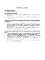
REMOTE CONTROLLER
A LED indicator E Panic Switch
B Arm F Key Chain Ring
C Part-Arm G Negative Polarity
D Disarm H Positive Polarity
The Remote Controller is used to Arm, Part-Arm and Disarm the system.
The Remote Controller also incorporates a Panic switch. Activating the Panic switch will immediately initiate a Full
Alarm condition whether the system is Armed or Disarmed, (unless the system is in Test mode).
The Remote Controller adopts a CR2032 type Lithium cell which under normal conditions will have typical life in
excess of 1 year. Under normal battery conditions the LED on the Remote controller will only illuminate when a
button is pressed. However, under low battery conditions this LED will flash every time the button is pressed.
When this occurs the batteries should be replaced as soon as possible.
SETTING THE REMOTE CONTROLLER
1. Remove the rear cover with a coin.
2. Insert the battery ensuring that the +v terminal faces upwards away from the PCB.
3. Replace the rear cover.

10
TESTING THE SYSTEM
With the Control Panel in Disarm Mode
Press
User access code
to enter test mode.
1. Trigger each detector on the system by either
walking into a Motion Sensor protected area or
by opening a door/window protected by a
Door/Window Contact detector. As each
detector is triggered the Control Panel will ding
dong to indicate that an alarm signal has been
received.
2. Operate detector tamper switches by opening
the case of the device. As the switches are
operated the Control Panel will ding dong.
3. Activate each button on the Remote Controller in
turn. As each button is pressed the Control
Panel will ding dong.
4. Press 3 seconds on the Control Panel, if
the wireless siren emits one long beep, the
wireless siren enters ‘system off’ mode, which
offers the flexibility of removing or changing
siren’s battery without triggering a full alarm
condition.
Press 3 seconds on the Control Panel, if
the wireless siren emits one long and two short
beeps, the wireless siren enters ‘system on’
mode. A full alarm condition will occur.
To get back to the normal mode, press on the
Control Panel to exit test mode.
MOTION SENSORS
Motion Sensors are designed to detect movement in a
protected area by detecting changes in infra-red
radiation levels caused when a person moves within or
across the devices field of vision. If movement is
detected an alarm signal will be emitted.
Note: Motion Sensors will also detect animals, so
ensure that pets are not permitted access to areas
fitted with Motion Sensors when the system is armed.
The Motion Sensor adopts 3 AA size 1.5V battery
which under normal conditions will have typical life in
excess of 1 year. When the battery level drops, with
the Motion Sensor in normal mode and the rear cover
fitted, the LED behind the detection window will flash
upon detecting movement. When this occurs the
batteries should be replaced as soon as possible.
Note: The adoption of alkaline battery is highly
recommended.
CHOOSING A MOUNTING LOCATION
The Motion Sensor is suitable for mounting in dry
interior locations only.
The recommended position for a Motion Sensor is in
the corner of a room mounted at a height between 1.8
and 2m. At this height, the sensor will have a
maximum range of up to 10m with a field of view of 110
°, subject to the position for the PCB being set in 1. The
position of the PCB inside the Motion Sensor can be
set to 5 different positions to adjust the range of the
detector. Setting the PCB in position 3 will reduce the
range to 7m approximately, with position 5 providing a
range of 5m approximately. The recommended
position setting for the PCB is in position 1.
110°
10M
U
9
1
3
5
7

11
PCB Position Range
1 10m
3 7m
5 5m
When considering and deciding upon the mounting
position for the sensor the following points should be
considered to ensure trouble free operation:
1. Do not locate the sensor facing a window or where
it is exposed to or facing direct sunlight. Motion
Sensors are not suitable for use in conservatories.
2. Do not locate the sensor where it is exposed to
ventilators.
3. Do not locate the sensor directly above a heat
source, (e.g. fire, radiator, boiler, etc).
4. Where possible, mount the sensor in the corner of
the room so that the logical path of an intruder
would cut across the fan detection pattern.
Motion Sensors respond more effectively to
movement across the device than to movement
directly towards it.
Less Sensitive More Sensitive
5. Do not locate the sensor in a position where it is
subject to excessive vibration
6. Ensure that the position selected for the motion
sensor is within effective range of the Control
Panel.
Note: When the system is armed, household pets
should not be allowed into an area protected by a
motion sensor as their movement would trigger the
motion sensor and generate an alarm.
INSTALLING THE MOTION SENSORS
Ensure that the system is in Test Mode.
1. Undo and remove the fixing screw from the bottom
edge of the Motion Sensor. Carefully pull the
bottom edge of the sensor away from the rear
cover and then slide down to release the top clips.
2. Carefully drill out the required mounting holes in
the rear cover using 3mm drill according to whether
the unit is being mounted in a corner or against a
flat wall.
Note: Using 1
st
mounting hole to fulfill corner
mounting installation, while 2
nd
mounting hole for
flat wall installation.
1
2
3
4
5
5
4
3
2
1
1st Mounting Hole Positions
2nd Mounting Hole Positions

12
3. Using the rear cover as a template, mark the
positions of the fixing holes on the wall.
4. Fix the rear cover to the wall using the two 18mm
screws and 23mm wall plugs. Do not over-tighten
the fixing screws as this may distort or damage the
cover.
5. Configure the Motion Sensor as described below.
Remember that on initial installation that the device
needs to be tested and should therefore be set in
Walk Test Mode.
6. Check that the sensor PCB is located and set in
the correct position to provide the required
detection range. To adjust the PCB position,
simply slide it up or down ensuring that the location
legs are aligned with the required position number
marked on the board.
7. To refit the Motion Sensor to the rear cover and
locate the clips in the top edge into the rear cover.
Push the lower edge of the sensor into place and
refit the fixing screw in the bottom edge of the
Sensor to secure in position. Do not over-tighten
the fixing screws as this may damage the casing.
SETTING THE MOTION SENSORS
Located on the PCB of the Motion Sensor is a
two-position DIP switch (SW2). When conducting the
Walk Test, ensure that the DIP switch SW2 is set as
follows:
SW2 DIP1 DIP2
ON
OFF
1. DIP1 of SW2 is used to configure the Motion
Sensor for walk test mode, which allows the
operation of the sensor to be checked during
installation without triggering a Full Alarm.
ON Walk Test mode
OFF Normal mode
Note: Remove batteries before setting the SW2.
Refit batteries after setting the SW2.
Note: On initial installation the sensor should be
set into Walk Test mode ready for testing. Upon
completion of Walk Test mode, set DIP1 of SW2 to
OFF for normal detection mode.
2. The Motion Sensor incorporates an anti-false
alarm feature designed to compensate for
situations where the sensor may be affected by
environmental changes, (e.g. insects, air
temperature, etc). This feature is called
“sensitivity detection” and may be selected for high
or low detection.
The recommended setting is for high sensitivity
detection. However, in cases of extreme
environmental problems or if unattributable false
alarms are experienced, it may be necessary to
select low sensitivity detection.
Set the required sensitivity detection using DIP2 of
SW2 as follows:
ON high sensitivity detection
OFF low sensitivity detection
Note: The higher the sensitivity detection the less
movement will be necessary before the Motion
sensor will trigger the alarm.
3. The setting of the DIP1 & DIP2 of SW2 can be
distinguished from the LED indication as follows:
On/Off
Selection
DIP1 of
SW2
DIP2 of
SW2
Trigger reaction of LED
High
Sensitivity
LED will be on once.
It implies high
sensitivity.
ON Walk Test
mode
Low
Sensitivity
LED will flash twice. It
implies low sensitivity.
Dip Switch(SW2)
1
ON
2
Tamper Switch
5
4
3
2
1

13
OFF Normal
mode
High/Low
Sensitivity
LED does not light up.
In summary, the setting of DIP1 & DIP2 of SW2 is
concluded as below:
SW2 DIP1 DIP2
ON Walk Test Mode High sensitivity
OFF Normal Mode Low sensitivity
4. Connect the AA 1.5V battery to the battery
compartment.
Note: When the battery is connected, the LED
behind the lens will flash for 2-3 minutes as
warming-up duration until the Sensor has stabilized
when the LED will then stop flashing and turn OFF.
5. In normal mode, remove the rear cover of the
Motion sensor. The Sensor’s LED will illuminate
and the Control Panel should alarm. It is because
the tamper switch fitted on the Detector has been
activated.
6. When the Sensor is fully installed i.e. rear cover is
refitted; the Sensor will not detect movement for
approximately 2 minutes after each activation.
(This feature is present to conserve battery power
and maximize the battery life).
7. In order to communicate with the Control Panel,
the ID code of the Sensor needs to be learned by
the Control Panel. By pressing the tamper switch
located adjacent to the PCB on the Sensor will
emit the ID code to the Control Panel instantly,
subject to the Control Panel being set at the ID
code learning mode.
TESTING THE MOTION SENSORS
Ensure the system is in test mode.
With the Motion sensor set in Walk Test mode and
mounted in position on the wall, allow 2-3 minutes for
the sensor to stabilize before commencing the Walk
Test.
1. Walk into and move slowly around the protected
area, each time the sensor senses movement the
LED behind the lens will flash. In addition, the
Control Panel will ding dong.
If necessary adjust the detection range by
changing the mounting position of the PCB within
the sensor housing.
Note: In normal operation, the LED behind the
Sensor lens will not flash on movement detection,
(unless the battery is low).
2. Remove the rear cover of the Motion Sensor. (this
is to test the operation of tamper switch) The
Control Panel should ding dong.
3. Press on the Control Panel to exit test
mode.
4. Reconfigure the Motion Sensor for normal mode
by setting DIP1 of SW2 to OFF and refit in
position.
DOOR/WINDOW CONTACT
DETECTOR(S)
The Door/Window contact consists of two parts; a
Detector and a Magnet. They are designed to be
fitted to doors or windows with the Magnet mounted on
the opening part and the Detector mounted on the fixed
frame. Opening the protected door/window will remove
the magnetic field, trigger the Detector and generate an
alarm condition, (if the system is armed).
The Detector is powered by 3 1.5V AAA size batteries
which under normal conditions will have typical life in
excess of 1 year. Under normal battery conditions
with rear cover fitted the LED on the Detector will not
illuminate when the Detector is triggered, (unless in
test mode). However, under low battery conditions this
LED will be illuminated when the detector is triggered.
When this occurs the battery should be replaced as
soon as possible.
Note: The adoption of alkaline battery is highly
recommended.
The Door/Window Contact Detector is of self-contained
wired Magnetic Contact (option). This contact must
be of a normally closed contact type with the contacts
being opened in order to generate an alarm condition.

14
CHOOSING A MOUNTING LOCATION
The Door/Window Contact Detector is suitable for
mounting in dry interior locations only.
Decide which doors/windows are to be protected by
Door/Window Contact Detectors, (usually the front and
back doors as a minimum will have Door/Window
Contact Detectors fitted). Additional detectors may
also be fitted where required to other vulnerable doors
or windows, (e.g. garage, patio/conservatory doors
etc).
Note: Take care when fixing the Detector to a metal
frame, or mounting within 1m of metalwork (i.e.
radiators, water pipes, etc) as this could affect the radio
range of the device. If required, it may be necessary
to space the magnet and detector away from the metal
surface using a plastic or wooden spacer to achieve
the necessary radio range.
INSTALLING THE DOOR/WINDOW
CONTACT DETECTORS
Ensure that the system is in Test Mode.
1. Undo and remove the fixing screw from the bottom
edge of the Detector. Remove the rear cover.
2. Fit 3 1.5V AAA batteries supplied to the battery
compartment.
3. With the tamper switch not being pressed on the
Detector, detach or close the magnet from the
Detector, the LED on the Detector will illuminate.
4. Using the rear cover as a template, mark the
positions of fixing holes on the fixed part of the
frame along the opening edge opposite the hinges
using screws provided.
5. Refit the Detector to the rear cover and secure with
the fixing screw supplied. Do not over tighten the
fixing screws as this may distort or damage the
casing.
6. Fit the Magnet to the moving part of the
door/window opposite the Detector using the
adhesive tape or 19mm fixing screws.
Ensure that the parallel gap between the Magnet
and Detector is less than 10mm and that the
matching line on the Magnet is pointing towards
and aligned with the line on the Detector.
7. If several windows need to be protected, remove
the self-contained wired supplied and adopt the
wire according to the specifications as mentioned
below. This should be wired to the terminal block
provided in the battery compartment in series
connection. The wired contact should be
connected using two core (24AWG) wire of
maximum length 1.5m.
A cable entry cut-out is available and adjacent to
the terminal block.
SETTING THE DOOR/WINDOW CONTACT
DETECTORS
1. Located on the PCB of the Detector is a
two-position DIP switch (SW2).
2. DIP switches 1-2 are used to enable/disable the
internal or external wired magnetic contact.
Dip Switch(SW2)
Tamper Switch

15
Internal connection External wired connection
DIP 1: ON
DIP 2: OFF
Only the internal contact will be
active.
DIP 1: OFF
DIP 2: ON
Only the external contacts will be
active.
DIP 1: ON
DIP 2: ON
Both contacts will be active. (Both
contacts must be all close, the
Detector will then be treated as close;
if one of the contacts is open, the
Detector will be treated as open.)
DIP 1: OFF
DIP 2: OFF
Only the internal contact will be
active.
Note: Remove batteries before setting the SW2. Refit
batteries after setting the SW2.
3. In order to communicate with the Control Panel,
the ID code of the Detector needs to be learned by
the Control Panel. By pressing the tamper switch
located at the rear cover of the Detector will emit
the ID code to the Control Panel instantly, subject
to the Control Panel being set at the ID code
learning mode.
TESTING THE DOOR/WINDOW CONTACT
DETECTORS
Ensure the system is in test mode.
1. Detach or close the magnet from the Detector, the
Control Panel will ding dong to indicate that the
alarm signal has been received.
2. Press to exit test mode.
FACTORY DEFAULTS
Disarm Mode Disarm
User Access Code 1 2 3 4
Key Tone On (enable)
Activation Type 1 Siren/Dialer enable
Alarm Duration 1 minute
Jamming Detection Off (disable)
Entry Delay 15 sec
for arm/part-arm
Off (disable)
SETTING
Q. Dip Switch
R. Jumper Link
JUMPER LINK
Setting Jumper link into the ON position will reset all of
the settings to factory default, such as all of ID codes,
phone number and alarm message.
DEFAULT
RESET
TOP VIEW

16
DIP SWITCH
There is a row of 8 DIP switches. These switches set
the House Code for the Control Panel and must be set
to the same ON/OFF combination as the House Code
DIP switches in the wireless siren.
1
2 3
4 5
6
7
8
ON
E C E

17
PROGRAMMING INSTRUCTIONS
ARM MODE
Press
User access code
Upon receipt of trigger signal, the Control Panel will
generate alarm condition right away.
Using remote controller, wireless keypad or press
keypad on the
User access code
Control Panel can disarm the alarm condition.
PART-ARM MODE
Press
User access code
Upon receipt of trigger signal from Zone 1, the Control
Panel will initiate full alarm condition.
Using remote controller, wireless keypad or press
keypad on the
User access code
Control Panel can disarm the alarm condition.
CHIME MODE
Press
User access code
Upon receipt of trigger signal from the detectors, the
Control Panel will ding dong twice.
DISARM MODE
Default setting: DISARM
Press
User access code
When full alarm condition occurs, disarm the alarm
using remote controller, wireless keypad or the keypad
on the Control Panel as mentioned above.
RECORDING ALARM MESSAGE
Press
User access code
Start recording message after beep is heard. Press any
keypad to stop recording. The maximum allowable
length of recording an alarm message is 6 seconds.
USER ACCESS CODE
Default setting: 1 2 3 4
Press
Default access code
Press
User access code
Press a new 4-digit user access code and then
within 15 seconds. This 15-second allows users to
enter a new access code. If a sequence of incorrect
access code is entered 3 times, the Control Panel will
exit this mode.
Press to exit
Any 4-digit
user access code mode.
PHONE NUMBER
Press
User access code
The maximum allowable length of inputting a set of
phone number is 30 seconds. Press
right after
the completion of each set of telephone number as

18
confirmation. During input, any incorrect digit number
can be erased by pressing each time. Up to 4
set of phone numbers can be memorized.
KEY TONE
This feature, if enabled, allows the Control Panel to be
emitted a tone each time the keypad is pressed.
Default setting: key tone enable
Press to disable
User access code
key tone.
Press again to
User access code
enable key tone.
CLEARING PHONE NUMBER
Press
User access code
The maximum allowable length of clearing all preset
phone numbers is 15 seconds. Once finished, refers
to “UI_Success” for confirmation.
LEARNING ID CODE / ZONE ASSIGNMENT
Press
User access code
The Control Panel will enter learning mode of which UI
indication refers to “UI_Wait”. The Control Panel has
a 30-second to learn one ID code from the
detector/remote controller/wireless keypad.
For detector, press the tamper switch on the detector
so as to emit ID code to the Control Panel.
Three LED will flash in sequence on the Control Panel,
it helps you to determine which zone the detector
should be assigned. Users have a 6-second to input
zone number. If the detector is to be assigned in Zone 1,
press keypad ; Zone 2, press keypad
;
whereas Panic zone, press keypad on the
Control Panel.
Note: It is recommended that the smoke detector and
flood detector are assigned to panic zone.
For wireless keypad, press the tamper switch on the
device so as to emit ID code to the Control Panel
automatically.
For remote controller, press any key on it so as to emit
ID code to the Control Panel automatically.
If failed refers to UI_Error indication for confirmation.
CLEARING ID CODE
Press
User access code
The Control Panel will enter clearing mode of which UI
indication refers to “UI_Wait”. Users have 15-second
to clear ID code.
Following is the instruction to clear ID code stored in
each zone.
Press for zone 1
User access code
Press for zone 2
User access code
Press for panic
User access code
Press for remote
User access code
Press for keypad
User access code
Press for all ID
User access code
ACTIVATION TYPE 1
This feature allows the siren and dialer take action
simultaneously when the Control Panel is triggered
configured for arm or part-arm mode.

19
Default setting: siren/dialer enable
Press
User access code
ACTIVATION TYPE 2
This feature allows the dialer dial up the preset phone
number in sequence when the Control Panel is
triggered configured for arm or part-arm mode.
Default setting: dialer enable
Press
User access code
Note: If Control Panel does not memorize any phone
number, no action will be taken when Control Panel is
triggered.
TEST MODE
Press
User access code
The maximum allowable length of testing the system is
10 minutes. If 10 minutes expires, UI indication refers
to “UI_Error” and exits test mode straight away. If test
is finished before 10 minutes is out, press to
exit this mode of which UI indication refers to
“UI_Success”.
While test is underway and the Control Panel receives
RF signal from the detector, the Control Panel will ding
dong.
During test mode, press keypad more than 3
seconds, the Control Panel will emit system on/system
off command to the wireless siren.
During test mode, press
keypad more than 3
seconds, the Control Panel will only dial up the first
preset phone number.
ALARM DURATION
This is the maximum length of time that the Control
Panel will sound for, following an intrusion. Alarm
duration can be set for either 1 or 3 minutes.
Press
User access code
The maximum allowable length of inputting the alarm
duration is 15 seconds.
Press for 1 minute
Press for 3 minute
If 15 seconds expires or a sequence of incorrect input
is entered 3 times, the Control Panel will exit this mode
of which UI indication refers to “UI_Error”.
JAMMING DETECTION
This feature controls the Control Panels RF jamming
detection circuitry, which if enabled, will continuously
scan for radio jamming signals on the system operating
frequency.
Default setting: off
Press
User access code
The maximum allowable length of selecting jamming
detection on or off is 15 seconds.
Press for on
Press for off
If 15 seconds expires or a sequence of incorrect input

20
is entered 3 times, the Control Panel will exit this mode
of which UI indication refers to “UI_Error”.
ENTRY DELAY
Default setting: off
Press
User access code
The entry delay is set for 15 seconds configured for
arm and part-arm mode.
The maximum allowable length of selecting entry delay
for on or off is 15 seconds.
Press for on
Press for off
If 15 seconds expires or a sequence of incorrect input
is entered 3 times, the Control Panel will exit this mode
of which UI indication refers to “UI_Error”.
Note: If entry delay is set for on, users have 15-second
to disarm the alarm before alarm goes off configured for
arm or part-arm mode. If alarm is not disarmed before
15-second is out, a full alarm condition will occur.
/