HP Latex 300 Printer Series
Site Preparation Guide
© Copyright 2016–2020 HP Development
Company, L.P.
Edition 4
Legal notices
The information contained herein is subject to
change without notice.
The only warranties for HP products and
services are set forth in the express warranty
statement accompanying such products and
services. Nothing herein should be construed as
constituting an additional warranty. HP shall not
be liable for technical or editorial errors or
omissions contained herein.
Table of contents
1 Overview ..................................................................................................................................................................................................... 1
Introduction ............................................................................................................................................................................... 1
Documentation ......................................................................................................................................................................... 1
Customer responsibility ........................................................................................................................................................... 1
Installation time schedule ....................................................................................................................................................... 2
2 Site preparation requirements ................................................................................................................................................................ 3
Physical space requirements .................................................................................................................................................. 3
Unloading route .................................................................................................................................................... 3
Environmental specications ............................................................................................................................. 4
Ventilation ............................................................................................................................................................. 4
Air conditioning ..................................................................................................................................................... 4
Designing the optimal print production area ....................................................................................................................... 5
RIP workstation characteristics .............................................................................................................................................. 5
Networking ................................................................................................................................................................................ 5
Printing supplies ....................................................................................................................................................................... 6
Return the site preparation checklist .................................................................................................................................... 6
Electrical conguration ............................................................................................................................................................ 6
Single phase power ............................................................................................................................................. 7
Circuit breakers ..................................................................................................................................................... 7
Wall receptacles and power cords ..................................................................................................................... 8
Powerline disturbances ......................................................................................................................................................... 11
Grounding ................................................................................................................................................................................ 11
3 Site preparation checklist ...................................................................................................................................................................... 12
ENWW iii
iv ENWW
1 Overview
Introduction
Your printer is supplied ready to use after a few simple installation procedures described in detail in the Assembly
instructions. It is important to read the information provided in this guide thoroughly and to ensure complete
compliance with all installation and operation requirements, safety procedures, warnings, cautions and local
regulations. A well prepared site helps to provide a smooth and easy installation.
Documentation
The following manuals are provided with your printer, and can also be downloaded from http://www.hp.com/go/
Latex300/manuals/:
Introductory information
Limited warranty
Legal information
Site preparation guide (this guide)
Assembly instructions
User's guide
Customer responsibility
You are responsible for preparing the physical site for the installation of the printer.
Prepare the building's electrical system to meet the printer's requirements and the Electrical Code
requirements according to the local jurisdiction of the country where the equipment is installed. See
Electrical conguration on page 6.
NOTE: Make sure that a certied electrician reviews the setup and conguration of the electrical system
used to power the printer. See Electrical conguration on page 6.
Meet temperature and humidity requirements and ensure proper ventilation for the printer. See
Environmental specications on page 4.
Meet all requirements for RIP, networking and printing supplies. See RIP workstation characteristics
on page 5, Networking on page 5 and Printing supplies on page 6.
Prepare the unloading route so the printer can be unloaded and maneuvered into place. See Unloading
route on page 3.
ENWW Introduction 1
Installation time schedule
Allow a minimum of three hours for the installation. The installer may require the help of three people to perform
certain tasks during installation.
2 Chapter 1 Overview ENWW
2 Site preparation requirements
Physical space requirements
Unloading route
The route between the unloading area of the printer and the installation site, including any corridors and
doorways through which the printer must be transported, is important to proper site preparation and must be
checked before the arrival of the printer. This pathway must be clear when the printer arrives.
Printer physical specications
315 Printer 335 Printer 365 Printer 375 Printer
Width 2307 mm (90.8 in) 2561 mm (101 in) 2561 mm (101 in) 2561 mm (101 in)
Depth 840 mm (33.07 in) 840 mm (33.07 in) 840 mm (33.07 in) 840 mm (33.07 in)
Height 1380 mm (54.3 in) 1380 mm (54.3 in) 1380 mm (54.3 in) 1380 mm (54.3 in)
Weight 174 kg (383.6 lb) 188 kg (414.5 lb) 207 kg (456.4 lb) 231 kg (510 lb)
Width with packaging 2541 mm (100 in) 2795 mm (110 in) 2795 mm (110 in) 2795 mm (110 in)
Depth with packaging 765 mm (30.1 in) 765 mm (30.1 in) 765 mm (30.1 in) 765 mm (30.1 in)
Height with packaging 1239 mm (48.8 in) 1239 mm (48.8 in) 1239 mm (48.8 in) 1705 mm (67.2 in)
Weight with packaging 290 kg (639.3 lb) 304 kg (670.2 lb) 323 kg (712.1 lb) 330 kg (728 lb)
Doorways: minimum width 1.01 m (40 in) × minimum height 1.67 m (66 in) required.
The space required for assembly is 3 m (10 ft) in front and 1 m (3.5 ft) at the sides and rear.
Most of the installation process requires one person, but four people are required to perform certain tasks.
ENWW Physical space requirements 3
Environmental specications
These environmental conditions must be kept within the specied ranges to ensure the correct operation of the
printer. Failure to do so may cause print-quality problems or damage sensitive electronic components.
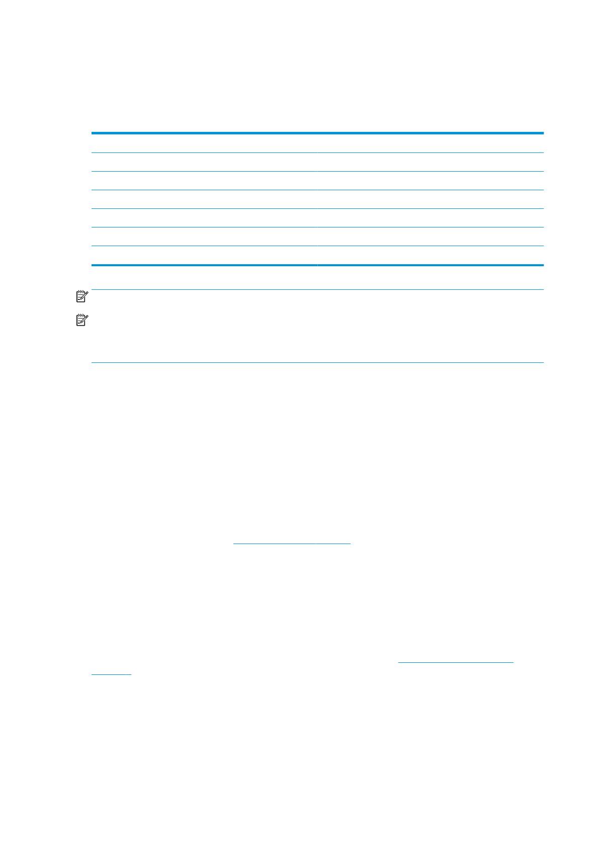
Printer environmental specications
Relative humidity range for best print quality 40–60%, depending on substrate type
Relative humidity range for printing 20–80%, depending on substrate type
Temperature range for best print quality 20 to 25°C (68 to 77°F), depending on substrate type
Temperature range for printing 15 to 30°C (59 to 86°F)
Temperature range when not in operation −25 to +55°C (−13 to +131°F)
Temperature gradient no more than 10°C/h (18°F/h)
Maximum altitude when printing 3000 m (10000 ft)
NOTE: The printer must be kept indoors.
NOTE: If the printer or ink cartridges are moved from a cold location to a warm and humid location, water from
the atmosphere can condensate on the printer parts and cartridges and can result in ink leaks and printer errors.
In this case, HP recommends that you wait at least 3 hours before turning on the printer or installing the ink
cartridges, to allow the condensate to evaporate.
In addition to controlling the temperature, humidity, and temperature gradient, there are other environmental
conditions that must be met during site preparation.
Do not install the printer where it will be exposed to direct sunlight or a strong light source.
Do not install the printer in a dusty environment. Remove any accumulated dust before moving the printer
into the area.
Ventilation
Ensure that the room in which the system is installed meets local environmental, health, and safety (EHS)
guidelines and regulations.
Adequate ventilation needs to be provided to ensure that potential exposure is adequately controlled. Consult
the Safety Data Sheets available at http://www.hp.com/go/msds to identify chemical ingredients of your ink
consumables.
Levels of certain substances in their facilities are dependent on workspace variables they control such as room
size, ventilation performance and duration of equipment use. Consult your EHS specialist for advice on the
appropriate measures for your location.
Air conditioning
In addition to fresh air ventilation, to avoid health hazards, also consider maintaining workplace ambient levels
by assuring the climatic operating conditions specied in this document (see Environmental specications
on page 4) to avoid operator's discomfort and equipment malfunction. Air conditioning in the work area should
take into account that the equipment produces heat. Typically, the printer's power dissipation is:
2.2 kW (7.5 kBTU/h) for HP Latex 315 Printers
2.6 kW (8.9 kBTU/h) for HP Latex 335 Printer
4.6 kW (15.7 kBTU/h) for HP Latex 365/375 Printers
Air conditioning should meet local environmental, health, and safety (EHS) guidelines and regulations.
4 Chapter 2 Site preparation requirements ENWW
NOTE: The air-conditioning units should not blow air onto the equipment.
Designing the optimal print production area
Your printer requires enough space to perform the following tasks:
Print
Replace a substrate roll
Service the printer or replace printer components
Ensure the printer is well ventilated
Your printer has the following dimensions:
Printer physical specications
315 Printer 335, 365, 375 Printer
Width 2307 mm (90.8 in) 2561 mm (101 in)
Depth 840 mm (33.07 in) 840 mm (33.07 in)
Height 1380 mm (54.3 in) 1380 mm (54.3 in)
The space required is illustrated in the following diagram:
RIP workstation characteristics
Each RIP has specic requirements. Check with your RIP vendor to nd out the requirements for the PC that you'll
be using for the RIP station. See http://www.hp.com/go/latexrips for a complete list of certied RIP stations
available for this printer. Make sure that the RIP station is fully functional and ready for installation.
Networking
You are responsible for all networking requirements, and you must complete the following tasks:
NOTE: In order to perform remote support, the printer must have access to the Internet using the LAN
connection.
Have a Gigabit Ethernet network ready for the day of installation.
Provide a CAT-6 LAN cable to connect the printer to your LAN and RIP workstation.
Provide a Gigabit Ethernet switch.
To get the full features for your printer, it should be connected to the Internet. Most unmanaged networks are
directly connected to the Internet. However, some networks require a web proxy. A proxy is a server that acts as
ENWW Designing the optimal print production area 5
an intermediary between computers on your local network and servers on the internet. Before setting up the
printer, please check if your network requires a web proxy.
To check this open Internet Explorer or Safari on any computer within your network, and browse to the http://
hp.com site. If you cannot connect to hp.com, your network does not have internet access and you need to
consult with your IT provider on how to congure internet access. If you can connect to hp.com, you can check
the browser settings for proxy conguration as follows:
For Internet Explorer, click Tools > Internet options > Connections > LAN settings. In the "Proxy server" part
of the window, if the Use a proxy server box is unchecked, you do not need a web proxy. If it is checked,
make a note of the address and port settings in the main window, or in the HTTP part of the Advanced
settings window.
For Safari, click Preferences > Advanced > Proxies > Change settings. If the Web proxy (HTTP) box is
unchecked, you do not need a web proxy. If it is checked, make a note of the Web Proxy Server name
(before the ":") and port (after the ":").
Proxy server names typically look like "proxy.mycompany.com", and the proxy port is typically 80, but
details are network dependent.
If you are unable to determine whether you need a web proxy or how to congure it, please consult with your
network administrator or Internet Service Provider. When in doubt, you probably do not need a web proxy.
Printing supplies
The following supplies should be purchased in addition to the printer and should be available on the day of
installation:
Six HP 831 ink cartridges, one for each color: black, cyan, magenta, yellow, light cyan and light magenta,
and one HP 831 optimizer cartridge.
At least one roll of substrate to perform calibrations and printhead alignment during printer setup.
Return the site preparation checklist
The checklist must be completed and returned to your reseller or service representative a minimum of two
weeks before the day of installation.
NOTE: Any delays during installation that are caused by an unprepared site will be charged to the customer.
Take care that your site is properly prepared to ensure a smooth and easy installation.
Electrical conguration
NOTE: If conguration of the building electrical system used to power the printer needs to be modied to meet
printer requirements, an electrician is required. Make sure that your electrician is appropriately certied according
to local regulations and supplied with all the information regarding the electrical conguration.
Your printer requires the following electrical components to be supplied and installed by the customer, according
to the Electrical Code requirements of the local jurisdiction of the country where the equipment is installed.
6 Chapter 2 Site preparation requirements ENWW
Single phase power
Single phase line specications
HP Latex 365/375 HP Latex 335 HP Latex 315
Printer Curing Printer Curing Printer Curing
Number of power
cords
2 2 2
Input voltage ~200–240 V (two wires and protective earth)
Input frequency 50 / 60 Hz
Maximum load
current (per
power cord)
16 A 16 A 3 A 16 A 3 A 13 A
Power
consumption per
power cord in
printing mode
2.5 kW 2.1 kW 200 W 2.4 kW 200 W 2.0 kW
Power
consumption in
ready mode
85 W 72 W 70 W
Circuit breakers
NOTE: The circuit breakers must meet the requirements of the printer and should be in accordance with the
Electrical Code requirements of the local jurisdiction of the country where the equipment is installed.
The printer requires two power cords that meet the following requirements.
Dedicated lines per SKU
HP Latex 365/375 HP Latex 335 HP Latex 315
Printer Curing Printer Curing Printer Curing
Dedicated line Yes Yes Not required. Do
not overload
lines. See Single
phase power
on page 7.
Yes Not required. Do
not overload
lines. See Single
phase power
on page 7.
Not required. Do
not overload
lines. See Single
phase power
on page 7.
Branch circuit
breaker
2 poles, 16 A/20 A according to local laws and printer maximum load current
Residual current
circuit breaker
(Also know as
Ground Fault
Circuit Interrupter
“GFCI”)
Required Recommended Recommended
2 poles, 30 mA residual, at least 20 A capacity
ENWW Electrical conguration 7
Electrical conguration diagram (for reference only)
NOTE: The Power Distribution Unit (PDU) must be rated to meet the power requirements of the printer, and
should be in accordance with the Electrical Code requirements of the local jurisdiction of the country where the
equipment is installed.
WARNING! Do not use a power strip (relocatable power tap) to connect both power cords.
Wall receptacles and power cords
Two power cords are provided with your printer, according to the printer's electrical specications. If those cords
do not reach your PDU and/or UPS, a certied electrician must install suitable extension cables on the day of
installation.
To make sure you have the right wall socket outlets (wall receptacles) ready for installation, check the following:
1. The wall socket outlets must be suitable for printer input ratings. See Single phase power on page 7.
2. The wall socket outlets must be suitable for the power cord plug type used in the country of installation.
The tables below list examples of the power cords and the plugs provided with the printer according to the
country. To make sure you have the right wall receptacle, nd your country in the appropriate table and
check the plug type.
WARNING! Use only use the power cord supplied by HP with the printer. Do not use a power strip
(relocatable power tap) to connect both power cords. Do not damage, cut, or repair the power cord. With a
damaged power cord, there is risk of re and electric shock. Always replace a damaged power cord with an
HP-approved power cord.
NOTE: You need two power cords from the tables below.
HP Latex 335/365/375 Printers—Power cord specications
Country HP part number Length Plug type Plug
Argentina 8121-0925 2.5 m IRAM 2073
Brazil 8121-1101 2.5 m NBR 14136
8 Chapter 2 Site preparation requirements ENWW
HP Latex 335/365/375 Printers—Power cord specications (continued)
Country HP part number Length Plug type Plug
Chile, Uruguay 8121-0923 2.5 m CEI 23-50
USA, Canada, Mexico, Japan,
Philippines, Thailand
8120-6360 2.5 m NEMA 6-20P, 240 V, 20 A,
non-locking
International 8121-1287 2.5 m IEC 60309, 240 V, 16 A, 2L
+PE
HP Latex 315 Printer—Power cord specications per region
Country HP part number Length Plug type Plug
America Region
Argentina 8121-0925 2.5 m IRAM 2073
Brazil 8121-1101 2.5 m NBR 14136
Chile, Uruguay 8121-0923 2.5 m CEI 23-50
USA, Canada, Mexico 8120-6360 2.5 m NEMA 6-20P, 240 V, 20 A,
non-locking
Asia Pacic and Japan Region
Australia/New Zealand 8120-6351 2.5 m AS/NZS 3112-3 (15A)
China 8121-0924 2.5 m GB 1002 (16A)
ENWW Electrical conguration 9
HP Latex 315 Printer—Power cord specications per region (continued)
Country HP part number Length Plug type Plug
Korea, Indonesia 8120-6352 2.5 m CEE 7-VII
India 8121-1074 2.5 m IS 1293
Taiwan 8121-1033 4.5 m CNS 690
Hong Kong, Singapore 8121-0907 2.5 m BS 1363/A (13A fused)
Japan, Philippines, Thailand 8120-6360 2.5 m NEMA 6-20P, 240 V, 20 A,
non-locking
Europe, Middle East and Africa Region
Europe Russia 8120-6352 2.5 m CEE 7-VII
Denmark 8121-1077 2.5 m DK 2-5A
Israel 8121-1010 2.5 m SI 32
South Africa 8121-0915 2.5 m SABS 164
Switzerland, Liechtenstein 8121-1287 2.5 m IEC 60309, 240 V, 16 A, 2L
+PE
10 Chapter 2 Site preparation requirements ENWW
HP Latex 315 Printer—Power cord specications per region (continued)
Country HP part number Length Plug type Plug
U.K. 8121–0907 2.5 m BS 1363/A (13A fused)
Middle East 8120-6360 2.5 m NEMA 6-20P, 240 V, 20 A,
non-locking
Appliance coupler (printer connection)
Country Appliance coupler (power cable) Appliance coupler inlet (printer)
All Detachable terminal as per IEC60320-1 C19 (squared
type)
Detachable inlet as per IEC60320-1 C20 (squared type)
NOTE: Place the wall receptacle close enough to the printer so the plug can be plugged and unplugged easily.
Powerline disturbances
As with all computer and electronic equipment, reliable operation of your printer depends on the availability of
relatively noise-free AC power.
In order to ensure optimum performance and reliability, your printer should be protected from variations in
line voltage. Lightning, line faults or the switching of lighting or machinery can generate line transients that
far exceed the peak value of the applied voltage. If not reduced, these microsecond pulses can disrupt
system operation and damage the printer.
It is recommended to include overvoltage (OVP) and transient protection in the power supply to the printer.
All electrical noise-generating equipment, such as fans, uorescent lighting and air-conditioning systems,
should be kept separate from the power source used for your printer.
Grounding
The printer must be connected to a good-quality ground line in order to avoid electrical risk. Please note your
obligation to comply with the Electrical Code requirements of the local jurisdiction of the country where the
equipment is installed.
The following grounding tasks must be fullled to meet the site preparation requirements:
Grounding wires must be insulated and at least equal in size to the phase conductors.
Ground impedance must be less than 0.5 Ω or comply with the Electrical Code requirements of the local
jurisdiction of the country where the equipment is installed.
ENWW Powerline disturbances 11
3 Site preparation checklist
Safety requirements Yes No Comments
Do those who will operate the printer have the technical training and experience
necessary to be aware of hazards to which they may be exposed in performing a
task, and to take appropriate measures to minimize the risks?
(Required)
Is there an emergency exit in the print production area, with easy access and free
from any obstruction?
Electrical installation requirements Yes No Comments
Is the electrician aware of all requirements and specications highlighted in this
guide?
(Required)
Is the single-phase line voltage inside the specied voltage range 200–240 V
(Required)
Specify nominal mains voltage:
Are there the dedicated lines to connect printer's power cords, if required?
NOTE: Do not use a power strip (relocatable power tap) to connect both power
cords.
(Required)
Have branch circuit breakers (2 poles, 16 A/20 A general) been correctly installed
for each dedicated line?
(Required)
Have the Residual Current Circuit Breaker (also known as Ground Fault Circuit
Interrupter) (2 poles, 30 mA residual, at least 20A capacity) been correctly installed
if required or recommended?
(Required)
Is the Power Distribution Unit (PDU) correctly installed? (Required)
Are the grounding conductors properly installed for each wall receptacle (wall
socket)?
(Required)
Are the wall receptacles (wall sockets) suitable for the power cord plug type
provided by HP?
(Required)
Are the wall receptacles (wall sockets) and electrical installation suitable for the
printer's rated current ?
NOTE: See Single phase power on page 7 for specic information.
(Required)
Are the wall receptacles (wall sockets) placed close enough to the printer that the
plugs can be plugged and unplugged easily?
NOTE: See Wall receptacles and power cords on page 8 for specic information.
(Required)
Electrical conguration requirements Yes No Comments
Do you need an Uninterrupted Power Supply (UPS) or step-up transformer? If so, is
it correctly installed?
12 Chapter 3 Site preparation checklist ENWW
Networking and computer requirements Yes No Comments
Is the RIP computer and software ready for installation?
Have network connections been supplied?
Do you need a web proxy? If so, write down proxy server name and port.
Do you have a color sensor that is compatible with your RIP?
Do you have a LAN cable long enough to connect the printer to the network?
Environmental requirements Yes No Comments
Have the temperature and humidity requirements been satisfactorily met in the
print production area?
Have the temperature and humidity requirements been satisfactorily met in the
storage area?
Is the print production area free from dirt and dust?
Does the print production area have suicient lighting?
Have you checked the required ventilation and air conditioning specications with
an expert?
Other requirements Yes No Comments
Have you arranged for supplies such as substrate and ink cartridges to be available
on the day of installation?
Have you met the requirements specied in this guide? (Required)
Date of site preparation completion
Site preparation guide edition number or copyright date
Customer signature
ENWW 13
  • Page 1 1
  • Page 2 2
  • Page 3 3
  • Page 4 4
  • Page 5 5
  • Page 6 6
  • Page 7 7
  • Page 8 8
  • Page 9 9
  • Page 10 10
  • Page 11 11
  • Page 12 12
  • Page 13 13
  • Page 14 14
  • Page 15 15
  • Page 16 16
  • Page 17 17

Ask a question and I''ll find the answer in the document

Finding information in a document is now easier with AI