
IMPORTANT: READ SAFETY RULES AND INSTRUCTIONS CAREFULLY
MTD PRODUCTS INC. P.O. BOX 368022 CLEVELAND, OHIO 44136-9722
Transmatic Lawn
Tractors
Model Series
660 thru 679
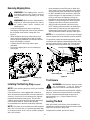
Warning: This unit is equipped with an internal combustion engine and should not be used on or near any unimproved forest-
covered, brush-covered or grass-covered land unless the engine’s exhaust system is equipped with a spark arrester meeting
applicable local or state laws (if any). If a spark arrester is used, it should be maintained in effective working order by the operator.
In the State of California the above is required by law (Section 4442 of the California Public Resources Code). Other states may have
similar laws. Federal laws apply on federal lands. A spark arrester for the muffler is available through your nearest engine authorized
service dealer or contact the service department, P.O. Box 368022 Cleveland, Ohio 44136-9722.
OPERATOR’S MANUAL
FORM NO.
770-10115D.fm
(1/2002)
PRINTED IN U.S.A.
ECO No.

2
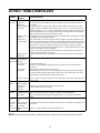
TABLE OF CONTENTS
Content Page
Important Safe Operation Practices...................................................................3
Slope Gauge......................................................................................................7
Assembling your Lawn Tractor..........................................................................8
Know Your Lawn Tractor ...................................................................................11
Operating Your Lawn Tractor.............................................................................13
Making Adjustments ..........................................................................................15
Service...............................................................................................................18
Maintaining your Lawn Tractor...........................................................................19
Off-Season Storage...........................................................................................23
Troubleshooting.................................................................................................24
FINDING MODEL NUMBER
This Operator’s Manual is an important part of your new Lawn Tractor. It will help you assemble, prepare
and maintain the unit for best performance. Please read and understand what it says.
Before you start assembling your new equipment, please locate the model plate on the
equipment and copy the information from it in the space provided below. The information on
the model plate is very important if you need help from our Customer Support Department or
an authorized dealer.
• You can locate the model number by pivoting the seat forward and looking under the seat at the seat
pivot bracket. A sample model plate is explained below. For future reference, please copy the model
number and the serial number of the equipment in the space below.
ENGINE INFORMATION
The engine manufacturer is responsible for all engine-related issues with regards to performance, power-
rating, specifications, warranty and service. Please refer to the engine manufacturer’s Owner’s/Operator’s
Manual packed separately with your unit for more information.
CALLING CUSTOMER SUPPORT
If you have difficulty assembling this product or have any questions regarding the controls, operation or
maintenance of this unit, please call the Customer Support Department.
Call 1- (330) 220-4MTD (4683) or 1- (800)-800-7310 to reach a Customer Support
representative. Please have your unit’s model number and serial number ready when you
call. See previous section to locate this information. You will be asked to enter the serial
number in order to process your call.
Copy the model number here:
Copy the serial number here:
(Model Number)
(Serial Number)
For more details about your unit, visit our website at www.mtdproducts.com

3
SECTION 1: IMPORTANT SAFE OPERATION PRACTICES
WARNING: This symbol points out important safety instructions which, if not followed, could endanger
the personal safety and/or property of yourself and others. Read and follow all instructions in this manual
before attempting to operate this machine. Failure to comply with these instructions may result in personal
injury. When you see this symbol—heed its warning.
DANGER: This machine was built to be operated according to the rules for safe operation in this man-
ual. As with any type of power equipment, carelessness or error on the part of the operator can result in
serious injury. This machine is capable of amputating hands and feet and throwing objects. Failure to
observe the following safety instructions could result in serious injury or death.
WARNING: Engine exhaust, some of its constituents, and certain vehicle components contain
or emit chemicals known to the State of California to cause cancer and birth defects or other
reproductive harm.
GENERAL OPERATION
1. Read, understand, and follow all instructions on the
machine and in the manual(s) before attempting to
assemble and operate. Keep this manual in a safe
place for future and regular reference and for
ordering replacement parts.
2. Be familiar with all controls and their proper
operation. Know how to stop the machine and
disengage them quickly.
3. Never allow children under 14 years old to operate
this machine. Children 14 years old and over
should read and understand the operation
instructions and safety rules in this manual and
should be trained and supervised by a parent.
4. Never allow adults to operate this machine without
proper instruction.
5. To help avoid blade contact or a thrown object
injury, keep bystanders, helpers, children and pets
at least 75 feet from the machine while it is in
operation. Stop machine if anyone enters the area.
6. Thoroughly inspect the area where the equipment
is to be used. Remove all stones, sticks, wire,
bones, toys, and other foreign objects which could
be picked up and thrown by the blade(s). Thrown
objects can cause serious personal injury.
7. Plan your mowing pattern to avoid discharge of
material toward roads, sidewalks, bystanders and
the like. Also, avoid discharging material against a
wall or obstruction which may cause discharged
material to ricochet back toward the operator.
8. Always wear safety glasses or safety goggles
during operation and while performing an
adjustment or repair to protect your eyes. Thrown
objects which ricochet can cause serious injury to
the eyes.
9. Wear sturdy, rough-soled work shoes and close-
fitting slacks and shirts. Loose fitting clothes and
jewelry can be caught in movable parts. Never
operate this machine in bare feet or sandals.
10. Be aware of the mower and attachment discharge
direction and do not point it at anyone. Do not
operate the mower without the discharge cover or
entire grass catcher in its proper place.
11. Do not put hands or feet near rotating parts or
under the cutting deck. Contact with the blade(s)
can amputate hands and feet.
12. A missing or damaged discharge cover can cause
blade contact or thrown object injuries.
13. Stop the blade(s) when crossing gravel drives,
walks, or roads and while not cutting grass.
14. Watch for traffic when operating near or crossing
roadways. This machine is not intended for use on
any public roadway.
15. Do not operate the machine while under the
influence of alcohol or drugs.
16. Mow only in daylight or good artificial light.
17. Never carry passengers.
18. Disengage blade(s) before shifting into reverse.
Back up slowly. Always look down and behind
before and while backing to avoid a back-over
accident.
19. Slow down before turning. Operate the machine
smoothly. Avoid erratic operation and excessive
speed.
20. Disengage blade(s), set parking brake, stop engine
and wait until the blade(s) come to a complete stop
before removing grass catcher, emptying grass,
unclogging chute, removing any grass or debris, or
making any adjustments.
21. Never leave a running machine unattended.
Always turn off blade(s), place transmission in
neutral, set parking brake, stop engine and remove
key before dismounting.
22. Use extra care when loading or unloading the
machine into a trailer or truck. This unit should not
be driven up or down ramp(s), because the unit
could tip over, causing serious personal injury. The
unit must be pushed manually on ramp(s) to load or
unload properly.

4
23. Muffler and engine become hot and can cause a
burn. Do not touch.
24. Check overhead clearances carefully before driving
under low hanging tree branches, wires, door
openings etc., where the operator may be struck or
pulled from the unit, which could result in serious
injury.
25. Disengage all attachment clutches, depress the
brake pedal completely and shift into neutral before
attempting to start engine.
26. Your machine is designed to cut normal residential
grass of a height no more than 10”. Do not attempt
to mow through unusually tall, dry grass (e.g.,
pasture) or piles of dry leaves. Dry grass or leaves
may contact the engine exhaust and/or build up on
the mower deck presenting a potential fire hazard.
27. Use only accessories and attachments approved
for this machine by the machine manufacturer.
Read, understand and follow all instructions
provided with the approved accessory or
attachment.
28. Data indicates that operators, age 60 years and
above, are involved in a large percentage of riding
mower-related injuries. These operators should
evaluate their ability to operate the riding mower
safely enough to protect themselves and others
from serious injury.
29. If situations occur which are not covered in this
manual, use care and good judgment. Contact your
customer service representative for assistance.
SLOPE OPERATION
Slopes are a major factor related to loss of control and
tip-over accidents which can result in severe injury or
death. All slopes require extra caution. If you cannot
back up the slope or if you feel uneasy on it, do not mow
it.
For your safety, use the slope gauge included as part of
this manual to measure slopes before operating this
unit on a sloped or hilly area. If the slope is greater than
15 degrees as shown on the slope gauge, do not
operate this unit on that area or serious injury could
result.
DO:
1. Mow up and down slopes, not across. Exercise
extreme caution when changing direction on
slopes.
2. Watch for holes, ruts, bumps, rocks, or other
hidden objects. Uneven terrain could overturn the
machine. Tall grass can hide obstacles.
3. Use slow speed. Choose a low enough speed
setting so that you will not have to stop or shift while
on the slope. Tires may lose traction on slopes
even though the brakes are functioning properly.
Always keep machine in gear when going down
slopes to take advantage of engine braking action.
4. Follow the manufacturer’s recommendations for
wheel weights or counterweights to improve
stability.
5. Use extra care with grass catchers or other
attachments. These can change the stability of the
machine.
6. Keep all movement on the slopes slow and gradual.
Do not make sudden changes in speed or direction.
Rapid engagement or braking could cause the front
of the machine to lift and rapidly flip over backwards
which could cause serious injury.
7. Avoid starting or stopping on a slope. If tires lose
traction, disengage the blade(s) and proceed
slowly straight down the slope.
DO NOT:
1. Do not turn on slopes unless necessary; then, turn
slowly and gradually downhill, if possible.
2. Do not mow near drop-offs, ditches or
embankments. The mower could suddenly turn
over if a wheel is over the edge of a cliff, ditch, or if
an edge caves in.
3. Do not try to stabilize the machine by putting your
foot on the ground.
4. Do not use a grass catcher on steep slopes.
5. Do not mow on wet grass. Reduced traction could
cause sliding.
6. Do not shift to neutral and coast downhill. Over-
speeding may cause the operator to lose control of
the machine resulting in serious injury or death.
7. Do not tow heavy pull behind attachments (e.g.
loaded dump cart, lawn roller, etc.) on slopes
greater than 5 degrees. When going down hill, the
extra weight tends to push the tractor and may
cause you to loose control. (e.g. tractor may speed
up, braking and steering ability are reduced,
attachment may jack-knife and cause tractor to
overturn).
CHILDREN
1. Tragic accidents can occur if the operator is not
alert to the presence of children. Children are often
attracted to the machine and the mowing activity.
They do not understand the dangers. Never
assume that children will remain where you last
saw them.
a. Keep children out of the mowing area and in
watchful care of a responsible adult other
than the operator.
b. Be alert and turn machine off if a child enters
the area.

5
c. Before and while backing, look behind and
down for small children.
d. Never carry children, even with the blade(s)
shut off. They may fall off and be seriously
injured or interfere with safe machine
operation.
e. Use extreme care when approaching blind
corners, doorways, shrubs, trees or other
objects that may block your vision of a child
who may run into the machine.
f. Disengage the cutting blade(s) before
shifting in reverse. The “No-Cut-In Reverse”
feature is a reminder not to cut in reverse and
to help avoid back over accidents. Do not
defeat it.
g. Keep children away from hot or running
engines. They can suffer burns from a hot
muffler.
h. Remove key when machine is unattended to
prevent unauthorized operation.
9. Never allow children under 14 years old to operate
the machine. Children 14 years old and over should
read and understand the operation instructions and
safety rules in this manual and should be trained
and supervised by a parent.
TOWING
1. Tow only with a machine that has a hitch designed
for towing. Do not attach towed equipment except
at the hitch point.
2. Follow the manufacturers recommendation for
weight limits for towed equipment and towing on
slopes.
3. Never allow children or others in or on towed
equipment.
4. On slopes, the weight of the towed equipment may
cause loss of traction and loss of control.
5. Travel slowly and allow extra distance to stop.
6. Do not shift to neutral and coast downhill.
SERVICE
SAFE HANDLING OF GASOLINE:
1. To avoid personal injury or property damage
use extreme care in handling gasoline. Gasoline is
extremely flammable and the vapors are explosive.
Serious personal injury can occur when gasoline is
spilled on yourself or your clothes which can ignite.
Wash your skin and change clothes immediately.
a. Use only an approved gasoline container.
b. Never fill containers inside a vehicle or on a
truck or trailer bed with a plastic liner. Always
place containers on the ground away from
your vehicle before filling.
c. When practical, remove gas-powered
equipment from the truck or trailer and refuel
it on the ground. If this is not possible, then
refuel such equipment on a trailer with a
portable container, rather than from a
gasoline dispenser nozzle.
d. Keep the nozzle in contact with the rim of the
fuel tank or container opening at all times
until fueling is complete. Do not use a nozzle
lock-open device.
e. Extinguish all cigarettes, cigars, pipes and
other sources of ignition.
f. Never fuel machine indoors.
g. Never remove gas cap or add fuel while the
engine is hot or running. Allow engine to cool
at least two minutes before refueling.
h. Never over fill fuel tank. Fill tank to no more
than ½ inch below bottom of filler neck to
allow space for fuel expansion.
i. Replace gasoline cap and tighten securely.
j. If gasoline is spilled, wipe it off the engine
and equipment. Move unit to another area.
Wait 5 minutes before starting the engine.
k. To reduce fire hazards, keep machine free of
grass, leaves, or other debris build-up. Clean
up oil or fuel spillage and remove any fuel
soaked debris.
l. Never store the machine or fuel container
inside where there is an open flame, spark or
pilot light as on a water heater, space heater,
furnace, clothes dryer or other gas
appliances.
m. Allow a machine to cool at least 5 minutes
before storing.
GENERAL SERVICE:
1. Never run an engine indoors or in a poorly
ventilated area. Engine exhaust contains carbon
monoxide, an odorless, and deadly gas.
2. Before cleaning, repairing, or inspecting, make
certain the blade(s) and all moving parts have
stopped. Disconnect the spark plug wire and
ground against the engine to prevent unintended
starting.
3. Periodically check to make sure the blades come to
complete stop within approximately (5) five
seconds after operating the blade disengagement
control. If the blades do not stop within the this time
frame, your unit should be serviced professionally
by an authorized MTD Service Dealer.
4. Check brake operation frequently as it is subjected
to wear during normal operation. Adjust and service
as required.
5. Check the blade(s) and engine mounting bolts at
frequent intervals for proper tightness. Also,
visually inspect blade(s) for damage (e.g.,
excessive wear, bent, cracked).

6
Replace the blade(s) with the original equipment
manufacturer’s (O.E.M.) blade(s) only, listed in this
manual. “Use of parts which do not meet the
original equipment specifications may lead to
improper performance and compromise safety!”
6. Mower blades are sharp. Wrap the blade or wear
gloves, and use extra caution when servicing them.
7. Keep all nuts, bolts, and screws tight to be sure the
equipment is in safe working condition.
8. Never tamper with the safety interlock system or
other safety devices. Check their proper operation
regularly.
9. After striking a foreign object, stop the engine,
disconnect the spark plug wire(s) and ground
against the engine. Thoroughly inspect the
machine for any damage. Repair the damage
before starting and operating.
10. Never attempt to make adjustments or repairs to
the machine while the engine is running.
11. Grass catcher components and the discharge
cover are subject to wear and damage which could
expose moving parts or allow objects to be thrown.
For safety protection, frequently check components
and replace immediately with original equipment
manufacturer’s (O.E.M.) parts only, listed in this
manual. “Use of parts which do not meet the
original equipment specifications may lead to
improper performance and compromise safety!”
12. Do not change the engine governor settings or
over-speed the engine. The governor controls the
maximum safe operating speed of the engine.
13. Maintain or replace safety and instruction labels, as
necessary.
14. Observe proper disposal laws and regulations for
gas, oil, etc. to protect the environment.
WARNING: YOUR RESPONSIBILITY- Restrict the use of this power machine to persons who
read, understand and follow the warnings and instructions in this manual and on the machine.

7
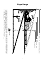
Slope Gauge
15°
SIGHT AND HOLD THIS LEVEL WITH A VERTICAL TREE
A POWER POLE
A CORNER OF A BUILDING
OR A FENCE POST
F
O
L
D
O
N
D
O
T
T
E
D
L
I
N
E
,
R
E
P
R
E
S
E
N
T
I
N
G
A
1
5
°
S
L
O
P
E
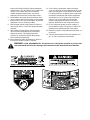
Do not mow on inclines with a slope in excess of 15 degrees (a rise of approximately 2-1/2 feet every 10 feet). A riding mower
could overturn and cause serious injury. If operating a walk-behind mower on such a slope, it is extremely difficult to maintain
your footing and you could slip, resulting in serious injury.
Operate RIDING mowers up and down slopes, never across the face of slopes.
O
p
e
r
a
t
e
W
A
L
K
-
B
E
H
I
N
D
m
o
w
e
r
s
a
c
r
o
s
s
t
h
e
f
a
c
e
o
f
s
l
o
p
e
s
,
n
e
v
e
r
u
p
a
n
d
d
o
w
n
s
l
o
p
e
s
.
WARNING

8
SECTION 1: ASSEMBLING YOUR LAWN TRACTOR
NOTE: Reference to right or left hand side of the unit
is observed from the driver’s seat, facing forward.
Tools Required For Assembly
(1) 1/2" wrench or socket wrench*
(1) 9/16" wrench or socket wrench
(2) 7/16" wrenches or socket wrenches
*If your steering wheel cap is square, you must have a
socket wrench in order to install the steering wheel.
Battery Information
• Battery acid must be handled with great care as
contact with it can burn and blister the skin. It is also
advisable to wear protective clothing (goggles,
rubber gloves and apron) when working with it.
• Should battery acid accidentally splatter into the
eyes or onto the face, rinse the affected area
immediately with clean cold water. If there is any
further discomfort, seek prompt medical attention.
• If acid spills on clothing, first dilute it with clean
water, then neutralize with a solution of ammonia/
water or baking soda/water.
• Since battery acid is corrosive, do not pour it into
any sink or drain. Before discarding empty
electrolyte containers, rinse them with a
neutralizing solution.
• NEVER connect or disconnect charger clips to
battery while charger is turned on as it can cause
sparks.
• Keep all lighted materials (cigarettes, matches,
lighters) away from the battery as the hydrogen gas
generated during charging can be combustible.
• As a further precaution, only charge the battery in a
well-ventilated area.
*Always shield eyes, protect skin and clothing when
working near batteries.
WARNING: Battery posts, terminals and
related accessories contain lead and lead
compounds. Wash hands after handling.
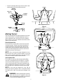
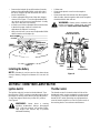
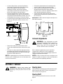
Attaching The Steering Wheel
• The hardware for attaching the steering wheel has
been packed inside the steering wheel. Carefully
pry off the steering wheel cap and remove the
hardware.
• Remove the steering bellow from the lift lever on
the right hand side of lawn tractor. Place steering
bellow over the steering shaft extending through
the dash. See Figure 1.
NOTE: If the openings on each end of the steering
bellow are two different sizes, the smaller end goes
down against the dash of the lawn tractor.
• With the wheels of the tractor pointing straight
forward, place the steering wheel over the steering
shaft, positioning steering wheel as desired.
• Place the washer with the cupped side down over
the steering shaft. Secure with hex lock bolt. See
Figure 1.
NOTE: If your steering wheel cap is square, you must
use a socket wrench.
IMPORTANT:
After assembly, service engine with
gasoline, and check oil level as instructed in the
separate engine manual packed with your unit.
WARNING
Battery contains sulfuric acid. Refer to warning
at right. Antidote: EXTERNAL—Flush with water.
INTERNAL—Drink large quantities of water or milk.
Follow with milk of magnesia, beaten eggs or
vegetable oil. Call physician immediately. EYES:
Flush with cool water for at least 15 minutes, then get
prompt medical attention.
Since batteries produce explosive gases, keep
all lighted materials (cigarettes, lighters,
matches, etc.) away. Be sure to charge battery only
in well-ventilated areas. Make certain venting path of
battery drain tube (if equipped) is always open.
KEEP BATTERIES
OUT OF THE REACH OF CHILDREN!
DANGER

9
• Place the steering wheel cap over the center of the
steering wheel and seat it with your hand.
Figure 1
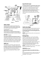
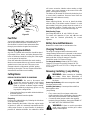
Attaching The Seat
There are two different seat pivot brackets used on this
series of lawn tractor, a manual adjustment seat or a
quick adjustment seat. See Figure 2 and 3 to identify
which seat is on your unit. Follow the instructions which
apply to your lawn tractor.
Manual Adjustment Seat
Remove the four screws which secure the seat to the
seat pivot bracket. Turn the seat around and place in
position against the seat pivot bracket, lining up the
slotted holes in the pivot bracket with the holes in the
seat. Select desired position for the seat, and secure
with the four screws. See Figure 2.
NOTE: Your seat may have been shipped in a box.
Remove the four screws from the bottom of seat and
place seat in position against the seat pivot bracket.
Follow the directions above to attach the seat.
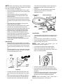
Quick Adjustment Seat
Pull out tab on seat stop and hold open while sliding
seat out of seat pivot bracket. See Figure 3. Turn the
seat around and line up plastic seat spacers with the
slots in seat pivot bracket. Slide seat in until front seat
spacer engages the seat stop. See Figure 4. To adjust
the seat refer to the adjustment section in this manual.
NOTE: If your seat was shipped in a box, line up
plastic seat spacers with the slots in seat pivot bracket
and slide seat in until front seat spacer engages seat
stop.
WARNING: Before operating this machine,
make sure the seat is engaged in the seat
stop, stand behind the machine and pull back
on seat until fully engaged into stop.
Figure 2
Figure 3
Figure 4
Steering
Wheel Cap
Hex Lock
Bolt
Steering
Shaft
Steering
Bellow
Cupped
Washer
Screws
Manual Adjustment Seat
Seat
Pivot
Bracket
Quick Adjustment Seat
Seat
Stop
Tab
Seat Pivot
Bracket
Quick Adjustment Seat
Seat
Spacers
Seat
Spacers
Slot
Slot
Seat
Stop

10
Removing Shipping Brace
WARNING: The shipping brace, used for
packaging purposes only, must be removed
and discarded before operating your riding
mower.
WARNING: Make sure the riding mower’s
engine is off, remove the ignition key, and set
the parking brake before removing the
shipping brace.
• Locate the shipping brace and accompanying
warning tag on the right side of the mower, between
the discharge chute and the cutting deck. See
Figure 5.
• While holding the discharge chute with your left
hand, remove the shipping brace with your right
hand by grasping it between your thumb and index
finger and rotating it clockwise.
• Carefully allow the discharge chute to pivot
downward.
• Discard the shipping brace and accompanying
warning tag.
Figure 5
Installing The Mulching Plug (If Equipped)
NOTE: Your mulching plug may already be installed
on the deck.
Some lawn tractors come equipped with a mulch kit
which incorporates special blades, already standard on
all tractor, in a process of recirculating grass clippings
repeatedly beneath the cutting deck. The ultra-fine
clippings are then forced back into the lawn where they
act as a natural fertilizer. Observe the following
recommendations for the best results when mulching.
NOTE: The mulch kit is installed on models equipped
with a 38” or 42-inch deck. It is packed separately (with
an instruction sheet) in the crate on models equipped
with a 46-inch deck.
• Never attempt to mulch if the lawn is damp. Wet
grass tends to stick to the underside of the cutting
deck preventing proper mulching of the clippings.
• Do NOT attempt to mulch more than 1/3 the total
height of the grass or approximately 1-1/2 inches.
Doing so will cause the clippings to clump up
beneath the deck and not be mulched effectively.
• Maintain a slow ground speed to allow the grass
clippings more time to effectively be mulched.
• Always position the throttle control lever in the
FAST (rabbit) position and allow it to remain there
while mowing. Failing to keep the engine at full
throttle places strain on the tractor’s engine and
does not allow the blades to properly mulch grass.
NOTE: It is not necessary to remove the discharge
chute to operate the mower with the mulch kit installed.
To operate the cutting deck without mulching, simply
remove the mulch plug by unthreading the plastic wing
nut which fastens it to the cutting deck. This will allow
the clippings to discharge out the side. See Figure 6.
Figure 6
Tire Pressure
WARNING: Maximum tire pressure under
any circumstances is 30 psi. Equal tire
pressure should be maintained at all times.
The tires on your unit may be over-inflated for shipping
purposes. Reduce the tire pressure before operating
the unit. Recommended operating tire pressure is
approximately 10 p.s.i. Check sidewall of tire for
maximum p.s.i.
Leveling The Deck
With unit on hard, level surface, place the blades in a
straight line, and measure the distance from the outside
edge of the blade tips to the ground.
If adjustment is needed, proceed as follows.
Shipping Brace
Warning Tag
Carriage Screw
Plastic Wing Nut
Bell
Washer
Mulch Plug

11
• Remove the hairpin clip and flat washer from the
bottom of the adjustable lift link on the left side of
the deck. (Hairpin clip and flat washer are on the
inside of the lift link.)
• Pull the adjustable lift link out of the deck hanger
channel. See Figure 7. Turn the adjustable lift link
up or down as necessary to level the deck. Usually
only one or two turns are needed.
• Insert the end of the adjustable lift link into the hole
in the deck hanger channel. Recheck the
adjustment. Readjust if necessary.
• When deck is level, secure end of adjustable lift link
with flat washer and hairpin clip.
Figure 7
Installing the Battery
NOTE: If battery is put into service after date shown
on top of battery, charge for minimum of 1 hour at 6-10
amps.
• Lift the seat.
• Remove the plastic cover from the negative
terminal.
• Remove the hex bolt and nut from the negative
(black) cable. Attach negative cable to the negative
terminal with this bolt and nut.
WARNING: Battery posts, terminals and
related accessories contain lead and lead
compounds. Wash hands after handling.
Figure 8
SECTION 2: KNOW YOUR LAWN TRACTOR
Ignition Switch
The ignition switch is located on the dashboard. Turn
the key to the START position to start the engine. When
the engine is running, leave the key in the ON position.
To stop the engine, turn the key to the OFF position.
See Figure 9.
WARNING: Never leave a running
machine unattended. Always disengaged
PTO, Shift into neutral, set parking brake,
stop engine and remove key to prevent
unintended starting.
Throttle Control
The throttle control is located on the left side of the
dashboard and is used to regulate the engine speed.
See Figure 9. The engine should be operated at full
throttle (FAST) when operating any equipment that
uses the tractor engine as a source of power such as
the mowing deck or snow thrower attachment.
Deck Hanger
Channel
Adjustable
Lift Link
Positive Terminal
(Inside Rubber Boot)
Battery
Strap
Negative
Cable
Negative
Terminal
Battery
Compartment

12
Figure 9
Choke Control
The choke control is located on the left side of the
dashboard and is operated manually. Details for the
choke operation are covered in the separate engine
manual packed with your unit. See Figure 9.
Light Switch (If Equipped)
The head lamps are operated by pushing the light
switch located on the dashboard. The head lamps will
only operate when the engine is running. See Figure 9.
Ammeter (If Equipped)
The ammeter registers the rate of battery charge or
discharge. The ammeter will register on the discharging
side with starting the engine. It should register on the
opposite side (charging) when the engine is running in
the fast position until the battery is completely charged.
With a fully charged battery or with the engine idling,
the ammeter will not show a charge. See Figure 9.
Shift Lever
The shift lever is located in the center of the console
and has three positions, FORWARD, NEUTRAL and
REVERSE. See Figure 9. The clutch-brake pedal must
be depressed and the lawn tractor must not be moving
when shifting gears. Do not force the shift lever.
Release the clutch-brake pedal slightly to line up the
shifting collar in the transmission. Then try to shift
gears.
Speed Control Lever
The speed control lever is located either on the console
or on the right fender. See Figure 10. The speed control
lever allows you to regulate the ground speed of the
lawn tractor. To select the ground speed, depress
clutch pedal. Move speed control lever out of the
notches and backward to slow lawn tractor, forward to
increase speed. When desired speed has been
obtained, release lever in that position. Whenever
clutch is released, unit will automatically go to the pre-
set speed.
Figure 10
Clutch-brake Pedal
The clutch-brake pedal is located on the left side of the
lawn tractor. Depressing the clutch-brake pedal part
way disengages the clutch. Pressing the pedal all the
way down disengages the clutch and engages the disc
brake. See Figure 9.
NOTE: The clutch-brake pedal must be depressed to
start the engine.
Parking Brake
The speed control lever is used to set the parking
brake. To set the parking brake, depress the clutch-
brake pedal. Move the speed control lever out of the
notches to the parking brake position. Release the
speed control lever and the clutch-brake pedal.
To release the parking brake, depress the clutch-brake
pedal and move the speed control lever out of the
notches to the desired position. Release the speed
control lever and the clutch-brake pedal.
NOTE: The parking brake must be set if the operator
leaves the seat with the engine running
Interlocks (Not Shown)
Interlock safety switches are located by the clutch-
brake pedal, the lift lever, the shift lever and under the
seat.
Before the engine will start, the clutch-brake pedal must
be depressed all the way and the lift lever must be in
the BLADES STOP position.
Shift Lever
Throttle
Control
Pedal
Ignition
Switch
Light
Switch
Ammeter
Choke
Control
Clutch-Brake
Speed
Control
Lever

13
Before the unit can be shifted into reverse or if the
operator leaves the seat, the lift lever must be in the
BLADES STOP position.
Indicator Lights (If Equipped)
If your unit is equipped with indicator lights, two or three
indicator lights are located in the dash panel. If a light
illuminates when attempting to start the unit, proceed
as follows.
CLUTCH—Depress the clutch pedal.
PTO—Place lift lever in the BLADES STOP position.
OIL (Vanguard Twin and Intek twin Engines Only)—
Check the crankcase oil level, and add oil as required.
Cutting Controls
Lift Lever
The lift lever is used to raise and lower the cutting deck
and to engage and disengage the blades. Pulling it all
the way back and locking it disengages the blades.
NOTE: The lift lever must be in the BLADES STOP
position when starting the engine, when shifting into
reverse and if the operator leaves the seat. See Figure
11.
Deck Lift Indicator (If Equipped)
If so equipped, the deck lift indicator marks the position
being used for the lift lever. Select the lift lever position
desired, press the indicator lever outward, move it to
the position immediately below the lift lever and release
the indicator lever. See Figure 11.
Setting The Cutting Height
• Select the position for the lift lever which gives the
desired cutting height. Move the deck lift indicator
(if so equipped) so that the lift lever can be returned
to the same position after it is raised.
• Move the deck wheels to the hole location so the
wheels are 1/4 inch above the ground. Place all
four wheels in the same relative position.
Figure 11
SECTION 3: OPERATING YOUR LAWN TRACTOR
AVOID SERIOUS INJURY OR DEATH
• Go up and down slopes, not across. avoid sudden
turns.
• Do not operate the unit where it could slip or tip.
• If machine stops going uphill, stop blade(s) and
back downhill slowly.
• Do not mow when children or others are around.
• Never carry children.
• Look down and behind before and while backing.
• Keep safety devices (guards, shields, and
switches) in place and working.
• Remove objects that could be thrown by the
blade(s).
• Know location and function of all controls.
• Be sure blade(s) and engine are stopped before
placing hands or feet near blade(s).
• before leaving operator’s position, disengage
blade(s), place the shift lever in neutral, engage
brake lock, shut engine off and remove key.
• READ OPERATOR’S MANUAL
Gas And Oil Fill-up
Check the oil level and add if necessary. Service
the engine with gasoline as instructed in the
separate engine manual packed with your tractor.
Read instructions carefully.
IMPORTANT:
Your tractor is shipped with oil; however
you must check the oil level before operating. Be
careful not to overfill.
WARNING: Use extreme care when
handling gasoline. Gasoline is extremely
flammable and the vapors are explosive.
Never fuel machine indoors or while the
engine is hot or running. Extinguish
cigarettes, cigars, pipes, and other sources
of ignition
Before Starting Engine
WARNING: Read, understand, and follow
all instructions and warnings on the machine
and in this manual before operating.
Lift Lever
Deck Lift
Indicator

14
Starting The Engine
IMPORTANT:
This unit is equipped with a safety
interlock system for your protection. The purpose of the
safety interlock system is to prevent the engine from
cranking or starting unless the clutch-brake pedal is
depressed and the lift lever is in the BLADES STOP
position. In addition, the lift lever must be in the
BLADES STOP position when the unit is put into
reverse or the engine will shut off. If the operator leaves
the seat with the lift lever engaged and/or without
setting the parking brake, the engine will shut off.
WARNING: Do not operate the tractor if
the interlock system is malfunctioning
because it is a safety device, designed for
protection.
• Place the lift lever in the BLADES STOP position.
• Depress the clutch-brake pedal and set the parking
brake.
• Set the throttle control in the FAST position.
• Pull out the choke control (a warm engine may not
require choking).
• Turn the ignition key to the right to the START
position. After the engine starts, release the key. It
will return to the ON position.
NOTE: Protect the starter life by using short starting
cycles of several seconds. Cranking more than 15
seconds per minute can damage the starter motor.
• Push choke knob in gradually. Move the throttle
control to desired engine speed.
Stopping The Engine
Turn the ignition key to the left to the OFF position.
Remove the key to prevent accidental starting.
WARNING: If you strike a foreign object,
stop the engine, disconnect the spark plug
wire(s) and ground against the engine.
Thoroughly inspect the machine for any
damage. Repair the damage before
restarting and operating.
NOTE: If any problems are encountered, refer to the
Trouble Shooting Guide.
Operating The Lawn Tractor
WARNING: Always look down and behind
before and while backing up to avoid a back-
over accident.
WARNING: Before leaving the operator’s
position. Always disengage PTO, shift into
neutral, set parking brake, stop engine and
remove key to prevent unintended starting.
• Move throttle control to full throttle to prevent strain
on the engine and to operate the cutting blades.
• Place the shift lever in either the FORWARD or
REVERSE position.
• Release the parking brake by depressing the
clutch-brake pedal, pressing outward on the speed
control lever and moving to desired position. Use
first speed position when operating the lawn tractor
for the first time.
• Release clutch-brake pedal slowly to put unit into
motion.
• The lawn tractor is brought to a stop by depressing
the clutch-brake pedal.
NOTE: When operating the unit initially, there will be
little difference between the highest two speeds until
after the belts have seated themselves into the pulleys
during the break-in period.
Be sure that the lawn is clear of stones, sticks, wire, or
other objects which could damage lawn mower or
engine. For best results and to insure more even grass
distribution, do not mow when lawn is excessively wet.
WARNING: Before leaving the operator’s
position for any reason, disengage the
blades, place the shift lever in neutral,
engage the parking brake, shut engine off
and remove the key.
When stopping the unit to empty a grass bag, etc.,
follow the instructions above. This procedure will also
eliminate ‘‘browning’’ the grass, which is caused by hot
exhaust gases from a running engine.
If unit stalls with speed control in high speed, or if unit
will not operate with speed control lever in a low speed
position, proceed as follows.
• Place shift lever in NEUTRAL.
• Restart engine.
• Place speed control lever in high speed position.
• Release clutch-brake pedal fully.
• Depress clutch-brake pedal.
• Place speed control lever in desired position.
• Place shift lever in either FORWARD or REVERSE,
and follow normal operating procedures.
Operating The Cutting Blades
The cutting blades may be engaged while the lawn
tractor is moving or standing still. DO NOT engage the
cutting blades abruptly as the sudden belt tension on
the pulley may cause the engine to stall.
WARNING: Keep feet and hands away
from the discharge opening, the blades or
any part of the deck. When the unit is used
for anything other than mowing operations,
the blade drive should be disengaged.
Move the lift lever into the BLADES STOP position to
raise the deck and disengage the blades.

15
Grass Collector Available
Grass Collector Model OEM-190-063 is available as
optional equipment for lawn tractors with 38" and 42"
decks. Grass Collector Model OEM-190-103 is
available for lawn tractors with 46" decks.
WARNING: Do not operate the cutting
deck unless the discharge cover or entire
grass catcher are in the proper operating
position.
NOTE: Under normal usage bag material is subject to
wear, and should be checked periodically. Be sure to
use only factory authorized replacement bag.
SECTION 4: MAKING ADJUSTMENTS
WARNING: Never attempt to make any
adjustments while the engine is running,
except where specified in the operator’s
manual.
WARNING: Disconnect the spark plug
wire(s) and ground against the engine before
performing any adjustments, repairs or
maintenance.
Manual Adjustment Seat
To adjust the position of the seat, loosen the four
screws on the bottom of the seat. See Figure 2. Slide
the seat forward or backward as desired. Retighten the
four screws.
Quick Adjustment Seat
To adjust the position of the seat, move the seat
adjustment lever (located under the seat) to the left and
slide the seat forward or backwards. See Figure 12.
Make sure seat is locked into one of the six adjustment
positions before operating the lawn tractor.
Figure 12
Carburetor Adjustments
WARNING: If any adjustments need to be
made to the engine while the engine is
running (e.g. carburetor), disengage PTO,
shift into neutral and set the parking brake.
Keep clear of all moving parts. Be careful of
muffler, engine and other surrounding
heated surfaces.
Minor carburetor adjustments may be required to
compensate for differences in fuel, temperature,
altitude and load. Refer to separate engine manual for
carburetor adjustment information.
NOTE: A dirty air cleaner will cause an engine to run
rough. Be certain air cleaner is clean and attached to
the carburetor before adjusting carburetor.
Deck Leveling Adjustment
If an uneven cut is obtained, the deck may be leveled
by following instructions in Assembly section.
Deck Engagement Adjustment
The cutting deck engagement may be adjusted to make
certain deck is disengaged when lift lever is in the
BLADES STOP position. Correct adjustment as
follows.
With the engine off, place the lift lever in the highest
cutting position (first position). Remove the cotter pin
and flat washer which secure the disengagement rod to
the stabilizer shaft assembly. See Figure 13. Shorten
the rod by threading it in until the ferrule is against the
back of the slot in the lift shaft assembly, and the rod
lines up with the hole in the stabilizer shaft. For more
belt tension the disengagement rod must be
lengthened. To decrease belt tension the
disengagement rod must be shortened.
Seat
Seat
Adjustment
Lever

16
Check the adjustment by placing the lift lever in the
BLADES STOP position. The deck should move up and
forward, allowing the belt to become loose. Start and
test for disengagement. Repeat procedure as
necessary.
Figure 13
Neutral Adjustment
• Place the transmission in neutral. (The unit will
move freely when pushed forward and backward
with the parking brake released.)
• Loosen the bolt which secures the shift lever
assembly to the shift lever link. See Figure 14.
• Place the shift lever in the neutral slot.
See Figure 14.
• Tighten the bolt to 13 foot pounds.
Figure 14
Brake Adjustment
The brake is located by the right rear wheel inside the
frame. During normal operation of this machine, the
brake is subject to wear and will require periodic
examination and adjustment.See Figure 15.
WARNING: Never attempt to adjust the
brake while the engine is running. Always
disengage PTO, shift to neutral, stop engine
and remove key to prevent unintended
starting.
To adjust the brake, adjust the nut so the brake starts to
engage when the brake lever is 1/4" to 5/16" away from
the axle housing.
Figure 15
Stabilizer Shaft
Assembly
Disengagement
Rod
Flat Washer
Hairpin Clip
Stabilizer Shaft
Assembly
Disengagement
Rod
Flat Washer
Hairpin Clip
38" Decks
Spring
Stabilizer Plate
42" and
46" Decks
Slot
Neutral
Lever
Shift
Loosen
Hex Bolt
Brake Lever
Nut
Disc
Brake

17
Figure 16
Speed Control Adjustment
NOTE: When operating the unit initially or after
replacing the belts, there will be little difference
between the highest two speeds until after the belts
have gone through a break-in period and have seated
themselves into the pulleys.
If the full range of speeds cannot be obtained on your
unit, adjust the speed control as follows.
• Adjust the speed control lever by pushing the
clutch-brake pedal forward until it hits the stop rod
on the running board. See Figure 16. Have another
person hold the pedal in this position as you make
the following adjustment. Place the speed control
lever in parking brake position. Remove the hairpin
clip and flat washer, and adjust the ferrule on the
rod so it is against the back end of the slot. See
Figure 16. Then lengthen rod one more turn.
Reassemble and secure with the flat washer and
hairpin clip.
• Adjust the speed control link as follows to obtain the
correct neutral adjustment.
• Start the engine.
• Place the shift lever in Neutral position.
• Place the speed control lever in high speed
position.
• Release the clutch-brake pedal completely, then
slowly depress the pedal all the way (to park
position). Hold the pedal in this position.
• Turn the engine off.
• After engine stops completely, release the clutch-
brake pedal.
• Place speed control lever in second position.
• Remove the cotter pin and flat washer which
secures the speed control link to the variable speed
torque bracket assembly.
• Push the clutch-brake pedal backward by hand as
far as it will go using light pressure. Hold it in this
position as you thread the speed control link in or
out of the ferrule until it lines up with the pin on the
variable speed torque bracket assembly.
• Secure speed control link to variable speed torque
bracket assembly with flat washer and cotter pin.
Wheel Adjustment
(Units With Adjustable Tie Rod)
If the tractor turns tighter in one direction than the other,
or if either the tie rod and ferrule are being replaced due
to damage or wear, the tie rod may need to be adjusted.
To do so, proceed as follows:
• Place the steering wheel in position for straight
ahead travel.
Speed Control Lever
Ferrule
Speed
Control
Rod
Variable Speed
Torque Bracket
Assembly
Speed
Control
Lever
Speed
Control
Link
Cotter Pin
and Flat Washer
Speed Control
Rod
Brake
Rod
Hairpin
Clip and
Flat Washer
Back
of Slot
Ferrule
Back of
Slot
Hairpin Clip
and Flat Washer
Stop Rod
Ferrule

18
• In front of the pivot bar, measure the distance
horizontally from the inside of the left rim to the
inside of the right rim. Note the distance.
• Behind the pivot bar, measure the distance
horizontally from the inside of the left rim to the
inside of the right rim. Note the distance.
• The measurement taken in front of the pivot bar
should be between 1/16” and 5/16” less than the
measurement taken behind the pivot bar. If it is not,
an adjustment is necessary. Proceed as follows.
• Locate the ferrule at the right end of the tie rod, just
to the rear of the right, front tire of tractor. See
Figure 17.
Figure 17
• Remove the cotter pin and flat washer which
secures the adjustment ferrule to the tractors right
axle.
• Two turns at a time, thread the adjustment ferrule
toward the right, front tire to lengthen the tie rod. Or,
thread the adjustment ferrule away from the right,
front tire to shorten the tie rod.
NOTE: Lengthening the tie rod increases the tractor’s
front tie toe-in. Shortening the tie rod decreases the
tractor’s front tire toe-in.
• Reinsert the adjustment ferrule and temporarily
secure it with the cotter pin removed earlier.
• Make certain the steering wheel is in position for
straight-ahead travel before again taking
measurements. Continue to repeat the steps above
until a proper adjustment is achieved.
• Secure the tie rod to the right axle with the flat
washer removed earlier and a replacement cotter
pin (714-0470).
IMPORTANT:
Do NOT reuse the original cotter pin once
it has been removed.
Figure 18
Carburetor Adjustments
WARNING: If any adjustments are made
to the engine while the engine is running (e.g.
carburetor), disengage all clutches and
blades. Keep clear of all moving parts. Be
careful of heated surfaces and muffler.
Minor carburetor adjustments may be required to
compensate for differences in fuel, temperature,
altitude and load. Refer to separate engine manual for
carburetor adjustment information.
NOTE: A dirty air cleaner will cause an engine to run
rough. Be certain air cleaner is clean and attached to
the carburetor before adjusting carburetor.
SECTION 5: SERVICE
WARNING: Always stop engine and
disconnect spark plug wire before cleaning,
lubricating or doing any kind of work on lawn
tractor.
Steering Gears
Lubricate teeth of steering gears with automotive multi-
purpose grease after every 25 hours of operation or
once a season. See Figure 19.
Steering Shaft
Lubricate steering shaft at least once a season with
light oil.
Tie Rod
Ferrule
Right Axle
Flat Washer
Cotter Pin
Right Front
Tire
(1/16" - 5/16" Less Than A)
A
B
Front

19
Figure 19
Linkage
Once a season lubricate all the pivot points on the
clutch, brake and lift linkage with SAE 30 engine oil.
Wheels
The front wheels may be provided with optional grease
fittings. The rear wheels must be removed from the axle
for lubrication. Lubricate at least once a season with
automotive multi-purpose grease.
Pivot Points
Lubricate all pivot points with light oil at least once a
season.
Ball Joints
The ball joints and drag link ends are permanently
lubricated.
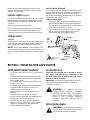
SECTION 6: MAINTAINING YOUR LAWN TRACTOR
WARNING: Disconnect the spark plug wire
and ground against the engine before
performing any adjustments, repairs or
maintenance.
Trouble Shooting
Refer to the trouble shooting chart for engine problems.
Engine
Refer to the separate engine manual for engine
maintenance instructions.
Service air cleaner every 10 hours under normal
conditions. Clean every few hours under extremely
dusty conditions. To service the air cleaner, refer to the
separate engine manual packed with your unit.
The spark plug(s) should be cleaned and the gap reset
once a season. Spark plug replacement is
recommended at the start of each mowing season;
check engine manual for correct plug type and gap
specifications.
Maintain engine oil as instructed in the separate
engine manual packed with your unit. Read and follow
instructions carefully.
Oil Drain Sleeve (If Equipped)
Your lawn tractor has a plastic oil drain sleeve packed
with the loose parts for your convenience in draining oil
from the crankcase. To drain the oil, snap small end of
oil drain sleeve onto oil sump. See Figure 20. Remove
drain plug and drain oil into a suitable container.
Figure 20
Oil Drain Valve (If Equipped)
Your lawn tractor may have a valve installed on the
engine for draining oil from the crankcase. See Figure
21. To drain the oil, insert the 12" hose (shipped loose
with your unit) over the end of the valve. Place the other
end in a suitable container. Push in black cap, rotate
counterclockwise and pull valve open. When oil is
completely drained, push top of valve in and rotate
clockwise to close.
Steering
Gears
Oil Drain
Sleeve
Sump
Oil

20
Figure 21
Fuel Filter
Your unit is equipped with a replaceable in-line fuel
filter. Replace filter whenever contamination or
discoloration is noticed. Order replacement filter
through your authorized engine service dealer.
Cleaning Engine And Deck
Any fuel or oil spilled on the machine should be wiped
off promptly. Grass, leaves, and other dirt must not be
left to accumulate around the cooling fins of the engine
or on any part of the machine.
Clean the underside of the deck after each mowing.
We do not recommend the use of pressure washers or
garden hose to clean your unit. They may cause
damage to electric components, spindles, pulleys,
bearings or the engine. The use of water will result in
shortened life and reduce serviceability.
Cutting Blades
REMOVAL FOR REPLACEMENT OR SHARPENING
WARNING: Be sure to disconnect and
ground the spark plug wire(s) and remove
ignition key before working on the cutting
blade to prevent accidental engine starting.
Protect hands by using heavy gloves or a rag
to grasp the cutting blades.
• Remove the hex flange nut which holds the blade to
the blade spindle.
• Remove the blade from the spindle.
Sharpening
Remove the cutting blades by following the directions
of the preceding section.
When sharpening the blades, follow the original angle
of grind as a guide. It is extremely important that each
cutting edge receives an equal amount of grinding to
prevent an unbalanced blade. An unbalanced blade
will cause excessive vibration when rotating at high
speeds, may cause damage to the mower and could
break, causing personal injury.
The blade can be tested for balance by balancing it on
a round shaft screwdriver. Remove metal from the
heavy side until it balances evenly.
Reassembly
When replacing blades, be sure to install the blade
with the side of the blade marked ‘‘Bottom’’ (or with
part number) facing the ground when the mower is in
the operating position. Carefully align “star” on blade
with “star” on spindle. Secure with hex flange nut.
Blade Mounting Torque
Hex Flange Nut: 840 in. lb. min., 1080 in. lb. max.
To ensure safe operation of your unit, all nuts and
bolts must be checked periodically for correct
tightness.
Battery Care And Maintenance
Batteries are sealed and are maintenance free.
Charging The Battery
The engine is equipped with an alternator which
charges battery when tractor is operated. Under normal
conditions, the battery only needs to be charged before,
during and after off-season storage. Follow the
instructions under “Off-Season Storage.”
To charge the battery: Battery P/N 725-1705D—
Charge at 2-3 amps for one hour. Battery P/N 725-
1707D, 725-0453G, and 725-1750—Charge at 6 amps
for one hour.
Removing / Installing / Jump Starting
WARNING: When removing or installing
the battery, follow these instructions to
prevent the screwdriver from shorting against
the frame.
Removing the Battery: Disconnect negative cable
first, then positive cable.
Installing the Battery: Connect positive cable first,
then negative cable.
Jump Starting
• First, connect end of one jumper cable to the
positive terminal of the good battery, then the other
end to the positive terminal of the dead battery.
• Connect the other jumper cable to the negative
terminal of the good battery, then to the FRAME OF
THE UNIT WITH THE DEAD BATTERY.
WARNING: Failure to use this procedure
could cause sparking, and the gas in either
battery could explode.
Oil Drain
Valve
12" Drain
Hose
Page is loading ...
Page is loading ...
Page is loading ...
Page is loading ...
Page is loading ...
Page is loading ...
Page is loading ...
Page is loading ...
-
 1
1
-
 2
2
-
 3
3
-
 4
4
-
 5
5
-
 6
6
-
 7
7
-
 8
8
-
 9
9
-
 10
10
-
 11
11
-
 12
12
-
 13
13
-
 14
14
-
 15
15
-
 16
16
-
 17
17
-
 18
18
-
 19
19
-
 20
20
-
 21
21
-
 22
22
-
 23
23
-
 24
24
-
 25
25
-
 26
26
-
 27
27
-
 28
28


Ask a question and I''ll find the answer in the document
Finding information in a document is now easier with AI