
Safety • Assembly • Operation • Adjustment • Maintenance • Troubleshooting • Warranty
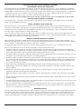
Warning: This unit is equipped with an internal combustion engine and should not be used on or near any unimproved forest-covered, brush-
covered or grass-covered land unless the engine’s exhaust system is equipped with a spark arrester meeting applicable local or state laws (if any).
If a spark arrester is used, it should be maintained in effective working order by the operator. In the State of California the above is required by law
(Section 4442 of the California Public Resources Code). Other states may have similar laws. Federal laws apply on federal lands. A spark arrester
for the muffler is available through your nearest engine authorized service dealer or contact the service department, P.O. Box 361131 Cleveland,
Ohio 44136-0019.
MTD LLC, P.O. BOX 361131 CLEVELAND, OHIO 44136-0019
PRINTED IN U.S.A.
READ SAFETY RULES AND INSTRUCTIONS CAREFULLY BEFORE OPERATION
IMPORTANT
OPERATOR’S MANUAL
Shift-On-The-Go
™
Lawn Tractor — Models 760-779
01/22/2007
FORM NO. 769-01598C

2
Finding and Recording Model Number
Model Number Serial Number
Please do
NOT
return the unit to the retailer from which it was
purchased, without first contacting Customer Support.
Table of Contents
BEFORE YOU START ASSEMBLING YOUR NEW EQUIPMENT,
please locate the model plate on the equipment and copy the
information to the sample model plate provided to the right. You
can locate the model plate by looking beneath the seat.
This information will be necessary to use the manufacturer’s web
site and/or obtain assistance from the Customer Support Depart-
ment or an authorized service dealer.
This Operator’s Manual is an important part of your new lawn tractor. It will help you assemble,
prepare and maintain the unit for best performance. Please read and understand what it says.
Customer Support
Slope Gauge........................................................ 3
Safe Operation Practices ................................... 4
Setting Up Your Lawn Tractor ............................ 8
Operating Your Lawn Tractor ........................... 12
Adjusting Your Lawn Tractor ............................ 20
Maintaining Your Lawn Tractor ........................ 22
Off-Season Storage / Attachments ................. 28
Safety Labels .................................................... 29
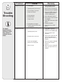
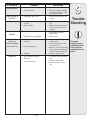
Trouble Shooting .............................................. 30
Warranty .............................................. Back Page
If you have difficulty assembling this product or have any questions regarding the controls, operation, or maintenance of this
unit, you can seek help from the experts. Choose from the options below:
1. Visit
www.mtdproducts.com.
2. Phone a
Customer Support Representative at 1 (800) 800-7310.
3. The
engine manufacturer is responsible for all engine-related issues with regards to performance, power-rating, specifica-
tions, warranty and service. Please refer to the engine manufacturer’s Owner’s/Operator’s Manual, packed separately with
your unit.

3
1
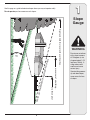
Slope
Gauge
WARNING
Do not mow on inclines
with a slope in excess
of 15 degrees (a rise
of approximately 2-1/2
feet every 10 feet). A
riding mower could
overturn and cause
serious injury.
Operate riding mowers
up and down slopes,
never across the face
of slopes.
3IGHTANDHOLDTHISLEVELWITHAVERTICALTREE
ORACORNEROFABUILDING
ORAFENCEPOST
&OLDALONGDOTTEDLINEREPRESENTSASLOPE
Use this page as a guide to determine slopes where you may not operate safely.
Do not operate your lawn mower on such slopes.

4
2
Safe
Operation
Practices
Children
1. Tragic accidents can occur if the operator is not
alert to the presence of children. Children are often
attracted to the machine and the mowing activity.
They do not understand the dangers. Never assume
that children will remain where you last saw them.
a. Keep children out of the mowing area and in
watchful care of a responsible adult other than
the operator.
b. Be alert and turn machine off if a child enters
the area.
c. Before and while backing, look behind and
down for small children.
d. Never carry children, even with the blade(s)
shut off. They may fall off and be seriously
injured or interfere with safe machine operation.
e. Use extreme care when approaching blind
corners, doorways, shrubs, trees or other
objects that may block your vision of a child
who may run into the machine.
f. To avoid back-over accidents, always
disengage the cutting blade(s) before
shifting into Reverse. If equipped, the
“Reverse Caution Mode” should not be
used when children or others are around.
g. Keep children away from hot or running
engines. They can suffer burns from a hot
muffler.
h. Remove key when machine is unattended to
prevent unauthorized operation.
2. Never allow children under 14 years old to operate
the machine. Children 14 years old and over should
read and understand the operation instructions and
safety rules in this manual and should be trained and
supervised by a parent.
Operation
Safe Handling of Gasoline:
1. To avoid personal injury or property damage use
extreme care in handling gasoline. Gasoline is
extremely flammable and the vapors are explo-
sive. Serious personal injury can occur when gasoline
is spilled on yourself or your clothes which can ignite.
Wash your skin and change clothes immediately.
a. Use only an approved gasoline container.
b. Never fill containers inside a vehicle or on a
truck or trailer bed with a plastic liner. Always
place containers on the ground away from
your vehicle before filling.
c. When practical, remove gas-powered
equipment from the truck or trailer and refuel it
on the ground. If this is not possible, then
refuel such equipment on a trailer with a
portable container, rather than from a gasoline
dispenser nozzle.
d. Keep the nozzle in contact with the rim of
the fuel tank or container opening at all
times until fueling is complete. Do not use a
nozzle lock-open device.
e. Extinguish all cigarettes, cigars, pipes and
other sources of ignition.
f. Never fuel machine indoors.
g. Never remove gas cap or add fuel while the
engine is hot or running. Allow engine to cool
at least two minutes before refueling.
h. Never over fill fuel tank. Fill tank to no more
than ½ inch below bottom of filler neck to
allow space for fuel expansion.
i. Replace gasoline cap and tighten securely.
j. If gasoline is spilled, wipe it off the engine
and equipment. Move unit to another area.
Wait 5 minutes before starting the engine.
k. To reduce fire hazards, keep machine free of
grass, leaves, or other debris build-up. Clean
up oil or fuel spillage and remove any fuel
soaked debris.
l. Never store the machine or fuel container
inside where there is an open flame, spark
or pilot light as on a water heater, space
heater, furnace, clothes dryer or other gas
appliances.
m. Allow a machine to cool at least five minutes
before storing.
WARNING: Engine Exhaust, some of its constituents, and certain vehicle compo-
nents contain or emit chemicals known to State of California to cause cancer and
birth defects or other reproductive harm.
WARNING
This symbol points
out important safety
instructions which, if
not followed, could
endanger the personal
safety and/or property
of yourself and others.
Read and follow all
instructions in this man-
ual before attempting to
operate this machine.
Failure to comply with
these instructions may
result in personal injury.
When you see this
symbol.
HEED ITS WARNING
Your
Responsibility
Restrict the use
of this power machine
to persons who read,
understand
and follow the warnings
and instructions
in this manual
DANGER: This machine was built to be operated according to the rules for safe operation in this
manual. As with any type of power equipment, carelessness or error on the part of the operator can
result in serious injury. This machine is capable of amputating hands and feet and throwing objects.
Failure to observe the following safety instructions could result in serious injury or death.

5
2
Safe
Operation
Practices
WARNING
This symbol points
out important safety
instructions which, if
not followed, could
endanger the personal
safety and/or property
of yourself and others.
Read and follow all
instructions in this man-
ual before attempting to
operate this machine.
Failure to comply with
these instructions may
result in personal injury.
When you see this
symbol.
HEED ITS WARNING
Your
Responsibility
Restrict the use
of this power machine
to persons who read,
understand
and follow the warnings
and instructions
in this manual
General Operation:
1. Read, understand, and follow all instructions on the
machine and in the manual(s) before attempting to
assemble and operate. Keep this manual in a safe
place for future and regular reference and for ordering
replacement parts.
2. Be familiar with all controls and their proper operation.
Know how to stop the machine and disengage them
quickly.
3. Never allow children under 14 years old to operate
this machine. Children 14 years old and over should
read and understand the operation instructions and
safety rules in this manual and should be trained and
supervised by a parent.
4. Never allow adults to operate this machine without
proper instruction.
5. To help avoid blade contact or a thrown object injury,
keep bystanders, helpers, children and pets at least
75 feet from the machine while it is in operation. Stop
machine if anyone enters the area.
6. Thoroughly inspect the area where the equipment is to
be used. Remove all stones, sticks, wire, bones, toys,
and other foreign objects which could be picked up
and thrown by the blade(s). Thrown objects can cause
serious personal injury.
7. Plan your mowing pattern to avoid discharge of
material toward roads, sidewalks, bystanders and the
like. Also, avoid discharging material against a wall or
obstruction which may cause discharged material to
ricochet back toward the operator.
8. Always wear safety glasses or safety goggles during
operation and while performing an adjustment or
repair to protect your eyes. Thrown objects which
ricochet can cause serious injury to the eyes.
9. Wear sturdy, rough-soled work shoes and close-fitting
slacks and shirts. Loose fitting clothes and jewelry
can be caught in movable parts. Never operate this
machine in bare feet or sandals.
10. Be aware of the mower and attachment discharge
direction and do not point it at anyone. Do not operate
the mower without the discharge cover or entire grass
catcher in its proper place.
11. Do not put hands or feet near rotating parts or under
the cutting deck. Contact with the blade(s) can
amputate hands and feet.
12. A missing or damaged discharge cover can cause
blade contact or thrown object injuries.
13. Stop the blade(s) when crossing gravel drives, walks,
or roads and while not cutting grass.
14. Watch for traffic when operating near or crossing
roadways. This machine is not intended for use on
any public roadway.
15. Do not operate the machine while under the influ-
ence of alcohol or drugs.
16. Mow only in daylight or good artificial light.
17. Never carry passengers.
18. Disengage blade(s) before shifting into reverse.
Back up slowly. Always look down and behind before
and while backing to avoid a back-over accident.
19. Slow down before turning. Operate the machine
smoothly. Avoid erratic operation and excessive
speed.
20. Disengage blade(s), set parking brake, stop engine
and wait until the blade(s) come to a complete stop
before removing grass catcher, emptying grass,
unclogging chute, removing any grass or debris, or
making any adjustments.
21. Never leave a running machine unattended. Always
turn off blade(s), place transmission in neutral, set
parking brake, stop engine and remove key before
dismounting.
22. Use extra care when loading or unloading the
machine into a trailer or truck. This unit should not
be driven up or down ramp(s), because the unit
could tip over, causing serious personal injury. The
unit must be pushed manually on ramp(s) to load or
unload properly.
23. Muffler and engine become hot and can cause a
burn. Do not touch.
24. Check overhead clearances carefully before driving
under low hanging tree branches, wires, door open-
ings etc., where the operator may be struck or pulled
from the unit, which could result in serious injury.
25. Disengage all attachment clutches, depress the
brake pedal completely and shift into neutral before
attempting to start engine.
26. Your machine is designed to cut normal residential
grass of a height no more than 10”. Do not attempt to
mow through unusually tall, dry grass (e.g., pasture)
or piles of dry leaves. Dry grass or leaves may
contact the engine exhaust and/or build up on the
mower deck presenting a potential fire hazard.
27. Use only accessories and attachments approved for
this machine by the machine manufacturer. Read,
understand and follow all instructions provided with
the approved accessory or attachment.
28. Data indicates that operators, age 60 years and
above, are involved in a large percentage of riding
mower-related injuries. These operators should
evaluate their ability to operate the riding mower
safely enough to protect themselves and others from
serious injury.
29. If situations occur which are not covered in this
manual, use care and good judgment. Contact your
customer service representative for assistance.

6
Slope Operation:
Slopes are a major factor related to loss of control and
tip-over accidents which can result in severe injury or
death. All slopes require extra caution. If you cannot
back up the slope or if you feel uneasy on it, do not mow
it.
For your safety, use the slope gauge included as part of
this manual to measure slopes before operating this unit
on a sloped or hilly area. If the slope is greater than 15
degrees as shown on the slope gauge, do not operate
this unit on that area or serious injury could result.
Do:
1. Mow up and down slopes, not across. Exercise
extreme caution when changing direction on slopes.
2. Watch for holes, ruts, bumps, rocks, or other hidden
objects. Uneven terrain could overturn the machine.
Tall grass can hide obstacles.
3. Use slow speed. Choose a low enough speed
setting so that you will not have to stop or shift while
on the slope. Tires may lose traction on slopes even
though the brakes are functioning properly. Always
keep machine in gear when going down slopes to
take advantage of engine braking action.
4. Follow the manufacturer’s recommendations for
wheel weights or counterweights to improve stability.
5. Use extra care with grass catchers or other at-
tachments. These can change the stability of the
machine.
6. Keep all movement on the slopes slow and gradual.
Do not make sudden changes in speed or direction.
Rapid engagement or braking could cause the front
of the machine to lift and rapidly flip over backwards
which could cause serious injury.
7. Avoid starting or stopping on a slope. If tires lose
traction, disengage the blade(s) and proceed slowly
straight down the slope.
Do Not:
1. Do not turn on slopes unless necessary; then, turn
slowly and gradually downhill, if possible.
2. Do not mow near drop-offs, ditches or embankments.
The mower could suddenly turn over if a wheel is over
the edge of a cliff, ditch, or if an edge caves in.
3. Do not try to stabilize the machine by putting your foot
on the ground.
4. Do not use a grass catcher on steep slopes.
5. Do not mow on wet grass. Reduced traction could
cause sliding.
6. Do not shift to neutral and coast downhill. Over-speed-
ing may cause the operator to lose control of the
machine resulting in serious injury or death.
7. Do not tow heavy pull behind attachments (e.g. loaded
dump cart, lawn roller, etc.) on slopes greater than
5 degrees. When going down hill, the extra weight
tends to push the tractor and may cause you to loose
control. (e.g. tractor may speed up, braking and steer-
ing ability are reduced, attachment may jack-knife and
cause tractor to overturn).
Towing:
1. Tow only with a machine that has a hitch designed for
towing. Do not attach towed equipment except at the
hitch point.
2. Follow the manufacturers recommendation for weight
limits for towed equipment and towing on slopes.
3. Never allow children or others in or on towed equip-
ment.
4. On slopes, the weight of the towed equipment may
cause loss of traction and loss of control.
5. Travel slowly and allow extra distance to stop.
6. Do not shift to neutral and coast downhill.
2
Safe
Operation
Practices
This symbol points
out important safety
instructions which, if
not followed, could
endanger the personal
safety and/or property
of yourself and others.
Read and follow all
instructions in this man-
ual before attempting to
operate this machine.
Failure to comply with
these instructions may
result in personal injury.
When you see this
symbol.
HEED ITS WARNING
Your
Responsibility
Restrict the use
of this power machine
to persons who read,
understand
and follow the warnings
and instructions
in this manual

7
2
Safe
Operation
Practices
This symbol points
out important safety
instructions which, if
not followed, could
endanger the personal
safety and/or property
of yourself and others.
Read and follow all
instructions in this man-
ual before attempting to
operate this machine.
Failure to comply with
these instructions may
result in personal injury.
When you see this
symbol.
HEED ITS WARNING
Your
Responsibility
Restrict the use
of this power machine
to persons who read,
understand
and follow the warnings
and instructions
in this manual
Service
1. Never run an engine indoors or in a poorly ventilated
area. Engine exhaust contains carbon monoxide, an
odorless, and deadly gas.
2. Before cleaning, repairing, or inspecting, make certain
the blade(s) and all moving parts have stopped.
Disconnect the spark plug wire and ground against the
engine to prevent unintended starting.
3. Periodically check to make sure the blades come to
complete stop within approximately (5) five seconds
after operating the blade disengagement control. If the
blades do not stop within the this time frame, your unit
should be serviced professionally by an authorized
MTD Service Dealer.
4. Check brake operation frequently as it is subjected to
wear during normal operation. Adjust and service as
required.
5. Check the blade(s) and engine mounting bolts at
frequent intervals for proper tightness. Also, visually
inspect blade(s) for damage (e.g., excessive wear,
bent, cracked). Replace the blade(s) with the original
equipment manufacturer’s (O.E.M.) blade(s) only,
listed in this manual. “Use of parts which do not meet
the original equipment specifications may lead to
improper performance and compromise safety!”
6. Mower blades are sharp. Wrap the blade or wear
gloves, and use extra caution when servicing them.
7. Keep all nuts, bolts, and screws tight to be sure the
equipment is in safe working condition.
8. Never tamper with the safety interlock system or other
safety devices. Check their proper operation regularly.
9. After striking a foreign object, stop the engine,
disconnect the spark plug wire(s) and ground against
the engine. Thoroughly inspect the machine for any
damage. Repair the damage before starting and
operating.
10. Never attempt to make adjustments or repairs to the
machine while the engine is running.
11. Grass catcher components and the discharge
cover are subject to wear and damage which could
expose moving parts or allow objects to be thrown.
For safety protection, frequently check components
and replace immediately with original equipment
manufacturer’s (O.E.M.) parts only, listed in this
manual. “Use of parts which do not meet the original
equipment specifications may lead to improper
performance and compromise safety!”
12. Do not change the engine governor settings or
over-speed the engine. The governor controls the
maximum safe operating speed of the engine.
13. Maintain or replace safety and instruction labels, as
necessary.
14. Observe proper disposal laws and regulations for
gas, oil, etc. to protect the environment.

8
3
Setting Up
Your Lawn
Tractor
NOTE: This Operators
Manual covers a range
of product specifications
for various models.
Characteristics and
features discussed
and/or illustrated in
this manual may not be
applicable to all models.
MTD LLC reserves the
right to change product
specifications, designs
and equipment without
notice and without incur-
ring obligation.
WARNING
Use extreme care
when handling
gasoline. Gasoline is
extremely flammable
and the vapors are
explosive. Never fuel
machine indoors
or while the engine
is hot or running.
Extinguish cigarettes,
cigars, pipes, and
other sources of
ignition.
NOTE: This Operators Manual covers a range of product
specifications for various models. Characteristics and fea-
tures discussed and/or illustrated in this manual may not
be applicable to all models. MTD LLC reserves the right
to change product specifications, designs and equipment
without notice and without incurring obligation.
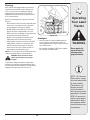
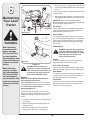
Attaching the Battery Cables
NOTE: Some models are shipped with the battery cables
already connected.
NOTE: The positive battery terminal is marked Pos. (+).
The negative battery terminal is marked Neg. (–).
• The positive cable (heavy red wire) is secured to the
positive battery terminal (+) with a hex bolt and hex
nut at the factory. Make certain that the rubber boot
covers the terminal to help protect it from corrosion.
• Remove the hex bolt and hex nut from the negative
cable.
• Remove the black plastic cover, if present, from the
negative battery terminal and attach the negative
cable (heavy black wire) to the negative battery
terminal (–) with the bolt and nut.
NOTE: If the battery is put into service after the date
shown on top/side of battery, charge the battery as
instructed in the Maintaining Your Lawn Tractor section of
this manual prior to operating the tractor.
Gas and Oil Fill-up
The gasoline tank is located under the hood and has a
capacity of 1-1/2 gallons. Do not overfill.
WARNING: Use extreme care when
handling gasoline. Gasoline is extremely
flammable and the vapors are explosive.
Never fuel machine indoors or while the
engine is hot or running. Extinguish ciga-
rettes, cigars, pipes, and other sources of
ignition.
Service the engine with gasoline and oil as instructed in
the separate Engine Operator/Owner Manual packed with
your tractor. Read instructions carefully.
IMPORTANT: Your tractor is shipped with motor oil in the
engine. However, you MUST check the oil level before
operating. Be careful not to overfill.
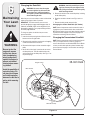
Shipping Brace Removal
WARNING: Make sure the riding mower’s
engine is off, remove the ignition key, and
set the parking brake before removing the
shipping brace.
Figure 3-1
Rubber Boot

9
3
WARNING
Make sure the riding
mower’s engine is
off, remove the igni-
tion key, and set the
parking brake before
removing the shipping
brace.
Setting Up
Your Lawn
Tractor
The shipping brace,
used for packaging
purposes only, must
be removed and
discarded before
operating your riding
mower.
The mowing deck is
capable of throwing
objects. Failure to
operate the riding
mower without the
discharge cover in
the proper operating
position could result
in serious personal
injury and/or property
damage.
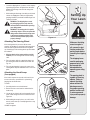
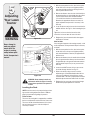
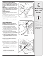
• Locate the shipping brace, if present, and accompany-
ing warning tag found on the right side of the mower,
between the discharge chute and the cutting deck.
See Fig. 3-2.
• While holding the discharge chute with your left hand,
remove the shipping brace with your right hand by
grasping it between your thumb and index finger and
rotating it clockwise.
WARNING: The shipping brace, used
for packaging purposes only, must be
removed and discarded before operating
your riding mower.
WARNING: The mowing deck is capable
of throwing objects. Failure to operate the
riding mower without the discharge cover
in the proper operating position could
result in serious personal injury and/or
property damage.
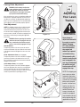
Attaching The Steering Wheel
If the steering wheel for your tractor did not come
attached, the hardware for attaching it has been packed
within the steering wheel, beneath the steering wheel
cap. Carefully pry off the steering wheel cap and remove
the hardware.
1. With the wheels of the tractor pointing straight
forward, place the steering wheel over the steering
shaft.
2. Place the washer (with the cupped side down) over
the steering shaft and secure with the hex bolt. See
Fig. 3-3.
3. Place the steering wheel cap over the center of the
steering wheel and push downward until it “clicks” into
place.
Attaching the Hood Scoop
(If so equipped)
If the hood scoop was not secured to the hood of your
tractor at the factory, you will find it in a plastic bag,
hanging from the throttle lever.
To install:
1. Carefully pivot the tractor hood forward.
2. Remove the four screws from the underside of the
hood scoop.
3. Line up the four holes in the hood scoop with the four
holes visible through the tractor’s hood louvres. See
Figure 3-4.
4. While holding the scoop in place, use a 3/8” socket
wrench (or box wrench) to carefully tighten the scoop
onto the hood.
Do NOT overtighten.
Figure 3-2
Figure 3-3
Figure 3-4

10
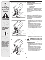
Attaching The Seat
Seat styles vary by tractor model and there are three
different styles available:
• Standard Adjustment
• Quick Adjustment &
• Knob Adjustment
If the seat for your tractor was not attached at the factory,
refer to Fig. 3-5, Fig. 3-6, and Fig. 3-7 to identify your
tractor’s seat style and follow the applicable instructions
below to attach it.
NOTE: For shipping reasons, seats are either fastened
to the tractor seat’s pivot bracket with a plastic tie, or
mounted backward to the pivot bracket. In either case,
free the seat form its shipping position and remove the
two hex screws (or knobs, on models so equipped) from
the bottom of seat before proceeding with applicable
instructions below.
Standard Adjustment Seat
1. Position the shoulder screws (found on the base of the
seat) inside the slot openings in the seat pivot bracket.
Fig. 3-5.
2. Slide the seat slightly rearward in the seat pivot
bracket, lining up the rear slots in the pivot bracket
with the remaining two holes in the seat’s base.
3. Select desired position for the seat, and secure with
the two hex screws removed earlier. See Fig. 3-5.
Quick Adjustment Seat
NOTE: If your seat was shipped mounted backwards on
the seat pivot bracket, pull out the tab found on the seat
stop and hold it open while sliding the seat off the seat
pivot bracket. See Fig. 3-6.
1. Line up the plastic seat spacers with the slots in seat
pivot bracket.
2. Slide seat in until front seat spacer engages the seat
stop. See Fig. 3-6.
WARNING: Before operating this machine,
make sure the seat is engaged in the seat
stop, stand behind the machine and pull
back on seat until fully engaged into stop.
Knob Adjustment Seat
1. Position the shoulder screws (found on the base of the
seat) inside the slot openings in the seat pivot bracket.
Fig. 3-7.
2. Slide the seat slightly rearward in the seat pivot
bracket, lining up the rear slots in the pivot bracket
with the remaining two holes in the seat’s base.
3. Select desired position for the seat, and secure with
the two knobs removed earlier. See Fig. 3-7.
3
Setting Up
Your Lawn
Tractor
NOTE: For shipping rea-
sons, seats are either
fastened to the tractor
seat’s pivot bracket with
a plastic tie, or mounted
backward to the pivot
bracket. In either case,
free the seat form its
shipping position and
remove the two hex
screws (or knobs, on
models so equipped)
from the bottom of seat
before proceeding with
applicable instructions.
WARNING
Before operating this
machine, make sure
the seat is engaged in
the seat stop, stand
behind the machine
and pull back on seat
until fully engaged
into stop.
Figure 3-5
Figure 3-6
Figure 3-7

11
3
WARNING
Setting Up
Your Lawn
Tractor
Figure 3-8
Identifying the Mulch Plug
On tractor models so equipped, a mulch plug can be
found within the cutting deck’s discharge opening.
NOTE: Refer to Mulching in the “Operating Your Lawn
Tractor” section of this manual for more detailed informa-
tion.
If you’d prefer to operate the cutting deck without mulch-
ing, simply remove the mulch plug by unthreading the
plastic wing nut which fastens it to the cutting deck. This
will allow the clippings to discharge out of the discharge
opening during operation. See Fig. 3-8.
Tire Pressure
WARNING: Maximum tire pressure under
any circumstances is 30 psi. Equal tire
pressure should be maintained at all times.
The tires on your unit may be over-inflated for shipping
purposes. Reduce the tire pressure before operating
the tractor. Recommended operating tire pressure is
approximately 10 p.s.i for the rear tires & 14 p.s.i. for the
front tires. Check sidewall of tire for maximum p.s.i.
Maximum tire pres-
sure under any
circumstances is 30
psi. Equal tire pressure
should be maintained
at all times.
NOTE: For shipping rea-
sons, seats are either
fastened to the tractor
seat’s pivot bracket with
a plastic tie, or mounted
backward to the pivot
bracket. In either case,
free the seat form its
shipping position and
remove the two hex
screws (or knobs, on
models so equipped)
from the bottom of seat
before proceeding with
applicable instructions.

12
4
Operating
Your Lawn
Tractor
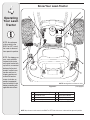
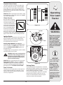
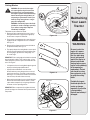
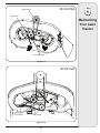
Know Your Lawn Tractor
Figure 4-1
A Speed Control Lever/ Parking Brake E Throttle Control Lever
B Clutch-Brake Pedal F Ignition Switch Module
C Shift Lever G Deck Lift Lever
D Choke Control† H PTO (Blade Engage) Lever
NOTE: Any reference in this manual to the RIGHT or LEFT side of the tractor is observed from operator’s position.
† If so equipped
NOTE: Any reference
in this manual to the
RIGHT or LEFT side of
the tractor is observed
from operator’s position.
NOTE: Steering wheel not shown for clarity
NOTE: For shipping rea-
sons, seats are either
fastened to the tractor
seat’s pivot bracket with
a plastic tie, or mounted
backward to the pivot
bracket. In either case,
free the seat form its
shipping position and
remove the two hex
screws (or knobs, on
models so equipped)
from the bottom of seat
before proceeding with
applicable instructions.
7
6
5
4
3
2
1
PARK
BRAKE
P
PARK
BRAKE :
To Se t Or
Rel ease , Fir st
Dep res s
Br ake Ped al,

13
4
Operating
Your Lawn
Tractor
WARNING
Never leave a running
machine unattended.
Always disengage
PTO, move shift lever
into neutral position,
set parking brake, stop
engine and remove key
to prevent unintended
starting.
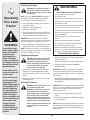
Throttle Control Lever
The throttle control lever is located on the right side of
the tractor’s dash panel. This lever controls the speed
of the engine and, on some models, when pushed all
the way forward, the choke control also. When set in a
given position, the throttle will maintain a uniform engine
speed. See Fig. 4-2.
IMPORTANT: When operating the tractor with the cutting
deck engaged, be certain that the throttle lever is always
in the FAST (rabbit) position.
Choke Control
On some models, moving the
throttle lever all the way forward
activates the engine’s choke
control. On all other models, the
choke control can be found on
the left side of the dash panel
and is activated by pulling the
knob outward. Activating the
choke control closes the choke
plate on the carburetor and aids
in starting the engine. Refer to Starting The Engine on
page 16 of this manual for detailed starting instructions.
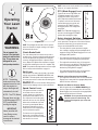
Ignition Switch
The ignition switch is activated to start the engine. Insert
key into the ignition switch and turn clockwise to the
START position. Release the key into the ON position
once engine has fired. See Fig. 4-3A.
Ignition Switch Module (If So Equipped)
To start the engine, insert the key into the ignition switch
and turn clockwise to the START position. Release the
key into the NORMAL MOWING MODE position once
the engine has fired.
To stop the engine, turn the ignition key counterclockwise
to the OFF position. See Fig. 4-3B.
WARNING: Never leave a running machine
unattended. Always disengage PTO, move
shift lever into neutral position, set park-
ing brake, stop engine and remove key to
prevent unintended starting.
IMPORTANT: Prior to operating the tractor, refer to both
Safety Interlock Switches on page 14 and Starting
The Engine on page 16 of this manual for detailed
instructions regarding the Ignition Switch Module and
operating the tractor in REVERSE CAUTION MODE.
Deck Lift Lever
Found on your tractor’s right fender, the deck lift lever is
used to change the height of the cutting deck. To use,
move the lever to the left, then place in the notch best
suited for your application.
Parking Brake
To set the parking brake, fully depress the clutch-brake
pedal. Move the speed control lever all the way down and
into the parking brake position. Release the clutch-brake
pedal to allow the parking brake to engage.
To release the parking brake, depress the clutch-brake
pedal and move the speed control lever out of the
notches to the desired position. Release the speed
control lever and the clutch-brake pedal.
&!34
3,/7
#(/+%
&!34
3,/7
Figure 4-2
Start
Position
Stop
Position
Normal
Mowing Mode
Start
On
A
B
Off
On/Lights
STOP
Figure 4-3
IMPORTANT
Prior to operating the
tractor, refer to both
Safety Interlock
Switches on page
14 and Starting The
Engine on page 16
of this manual for
detailed instructions
regarding the Ignition
Switch Module and
operating the tractor in
REVERSE CAUTION
MODE.

14
NOTE: The parking brake must be set if the operator
leaves the seat with the engine running or the engine
will automatically shut off.
Clutch-Brake Pedal
The clutch-brake pedal is located on the left side of
the lawn tractor, along the running board. Depress the
clutch-brake pedal part way down when slowing the
tractor by changing speeds (Refer to Speed Control
Lever). Depress the pedal all the way down to engage
the disc brake and bring the tractor to a complete stop.
NOTE: The pedal must be depressed to start the engine.
Refer to Safety Interlock Switches on page 14.
Shift Lever
The shift lever is located on the left side of the fender
and has three positions, FORWARD, NEUTRAL and
REVERSE. The brake pedal must be depressed and
the tractor must not be in motion when the moving shift
lever. See Fig. 4-4.
IMPORTANT: Never force the shift lever. Doing so may
result in serious damage to the tractor’s transmission.
Speed Control Lever
The speed control lever, located on
the left side of the tractor’s dash
console, allows you to regulate the
ground speed of the lawn tractor. To
use, depress the clutch-brake pedal
and move the lever out of the parking
brake notch and forward to increase
the tractor’s ground speed. When a
desired speed has been reached,
release the lever into an appropriate
notch to maintain that speed.
To slow the tractor’s ground speed,
depress the clutch-brake pedal and
move the speed control lever rearward
and release it into a notch.
4
Operating
Your Lawn
Tractor
NOTE: Lawn tractors vary by model and are available with
either a 6- or 7-speed control lever.
PTO (Blade Engage) Lever
Found on the tractor’s right fender, the
PTO (blade engage) lever is used to
engage power to the cutting deck or
other (separately available) attachments.
To operate, move the lever all the way
forward. Moving the lever all the way
rearward into the PTO OFF position
disengages power to the cutting deck/
attachment.
NOTE: The PTO (blade engage) lever
must be in the disengaged (PTO OFF)
position when starting the engine.
Safety Interlock Switches
This tractor is equipped with a safety interlock system
for the protection of the operator. If the interlock system
should ever malfunction, do not operate the tractor.
Contact an authorized MTD service dealer.
• The safety interlock system prevents the engine
from cranking or starting unless the parking brake is
engaged, and the PTO (Blade Engage) lever is in the
disengaged (OFF) position.
• The engine will automatically shut off if the operator
leaves the seat before engaging the parking brake.
• The engine will automatically shut off if the operator
leaves the tractor’s seat with the PTO (Blade Engage)
lever in the engaged (ON) position, regardless of
whether the parking brake is engaged.
• The engine will automatically shut off if the operator
engages the PTO with the parking brake ON.
Models without Reverse Caution Mode
• The engine will automatically shut off if the PTO (Blade
Engage) lever is moved into the engaged (ON) position
with the shift lever in Reverse.
Models with Reverse Caution Mode
• With the ignition key in the NORMAL MOWING posi-
tion, the engine will automatically shut off if the PTO
(Blade Engage) lever is moved into the engaged (ON)
position with the shift lever in Reverse.
WARNING: Do not operate the tractor if the
interlock system is malfunctioning. This
system was designed for your safety and
protection.
NOTE: The PTO (Blade
Engage) lever must be
in the disengaged (PTO
OFF) position when
starting the engine.
0!2+
"2!+%
0
&
&/27!2$
.5%42!,
2%6%23%
.
2
Figure 4-4
04/",!$%%.'!'%
04//&&
04//.
NOTE: The parking
brake must be set if the
operator leaves the seat
with the engine run-
ning or the engine will
automatically shut off.
IMPORTANT
Never force the shift
lever. Doing so may
result in serious
damage to the tractor’s
transmission.
WARNING
Do not operate the
tractor if the interlock
system is malfunction-
ing. This system was
designed for your
safety and protection.

15
4
Operating
Your Lawn
Tractor
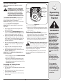
Reverse Caution Mode
(Models equipped with ignition switch
module)
WARNING: Use extreme caution while
operating the tractor in the REVERSE
CAUTION MODE. Always look down and
behind before and while backing. Do
not operate the tractor when children
or others are around. Stop the tractor
immediately if someone enters the area.
The REVERSE CAUTION MODE position of the key
switch module allows the tractor to be operated in
reverse with the blades (PTO) engaged.
IMPORTANT: Mowing in reverse is not recommended.
To use the REVERSE CAUTION MODE:
IMPORTANT: The operator MUST be seated in the
tractor seat.
1. Start the engine as instructed on page 16 under
Starting The Engine.
2. Turn the key from the NORMAL MOWING (Green)
position to the REVERSE CAUTION MODE (Yellow)
position of the key switch module. See Fig. 4-5.
3. Depress the REVERSE PUSH BUTTON (Orange,
Triangular Button) at the top, right corner of the key
switch module. The red indicator light at the top, left
corner of the key switch module will be ON while
activated. See Fig. 4-5.
4. Once activated (indicator light
ON), the tractor can
be driven in reverse with the cutting blades (PTO)
engaged.
5. Always look down and behind before and while
backing to make sure no children are around.
6. After resuming forward motion, return the key to the
NORMAL MOWING position.
IMPORTANT: The REVERSE CAUTION MODE will
remain activated until:
a. The key is placed in either the NORMAL MOWING
position or STOP position.
b. The operator engages the parking brake by fully
depressing the clutch-brake pedal and holding it
down while moving the speed control lever into the
PARK BRAKE position.
Engaging the Parking Brake
To engage the parking brake:
1. Fully depress the clutch-brake pedal and hold it down
with your foot.
2. Move the speed control lever all the way down and
into the parking brake position.
3. Release the clutch-brake pedal to allow the parking
brake to engage.
To release the parking brake:
1. Depress the clutch-brake pedal and move the speed
control lever out of the parking brake position and into
a desired speed.
Setting the Cutting Height
1. Select the height position of the cutting deck by plac-
ing the deck lift lever in any of the six different cutting
height notches on the right side of the fender.
2. Adjust the deck wheels, if equipped, so that they are
between ¼-inch and ½-inch above the ground when
the tractor is on a smooth, flat surface such as a
driveway.
WARNING: Keep hands and feet away from
the discharge opening of the cutting deck.
NOTE: On models so equipped, the deck wheels are an
anti-scalp feature of the deck and are not designed to
support the weight of the cutting deck.
Refer to Leveling the Deck on page 20 of this manual
for more detailed instructions regarding various deck
adjustments.
WARNING
Keep hands and
feet away from the
discharge opening of
the cutting deck.
Do not operate
the tractor if the
interlock system is
malfunctioning. This
system was designed
for your safety and
protection.
3TART
0OSITION
3TOP
0OSITION
2EVERSE
0USH"UTTON
2EVERSE
#AUTION-ODE
0OSITION
)NDICATOR
,IGHT
Figure 4-5
Use extreme caution
while operating
the tractor in the
REVERSE CAUTION
MODE. Always look
down and behind
before and while
backing. Do not oper-
ate the tractor when
children or others
are around. Stop the
tractor immediately if
someone enters the
area.

16
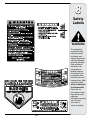
WARNING
AVOID SERIOUS INJURY OR DEATH
• GO UP AND DOWN SLOPES, NOT ACROSS.
• AVOID SUDDEN TURNS.
• DO NOT OPERATE THE UNIT WHERE IT COULD SLIP OR TIP.
• IF MACHINE STOPS GOING UPHILL, STOP BLADE(S) AND
BACK DOWNHILL SLOWLY.
• DO NOT MOW WHEN CHILDREN OR OTHERS ARE AROUND.
• NEVER CARRY CHILDREN, EVEN WITH BLADES OFF.
• LOOK DOWN AND BEHIND BEFORE AND WHILE BACKING.
• KEEP SAFETY DEVICES (GUARDS, SHIELDS, AND SWITCHES)
IN PLACE AND WORKING.
• REMOVE OBJECTS THAT COULD BE THROWN BY THE
BLADE(S).
• KNOW LOCATION AND FUNCTION OF ALL CONTROLS.
• BE SURE BLADE(S) AND ENGINE ARE STOPPED BEFORE
PLACING HANDS OR FEET NEAR BLADE(S).
• BEFORE LEAVING OPERATOR’S POSITION, DISENGAGE
BLADE(S), PLACE THE SHIFT LEVER IN NEUTRAL, ENGAGE
BRAKE LOCK, SHUT ENGINE OFF AND REMOVE KEY.
READ OPERATOR’S MANUAL
1. Depress the brake pedal to release the parking brake
and let the pedal up.
2. Move the throttle lever into the FAST (rabbit) position.
3. Place the shift lever in either the FORWARD or
REVERSE position.
IMPORTANT: Do NOT use the shift lever to change the
direction of travel when the tractor is in motion. Always
use the brake pedal to bring the tractor to a complete stop
before shifting.
4. Release the parking brake by depressing the clutch-
brake pedal and positioning the speed control lever in
desired position.
IMPORTANT: First-time operators should use speed posi-
tions 1 or 2. Become completely familiar with the tractor’s
operation and controls before operating the tractor in
higher speed positions.
5. Release clutch-brake pedal slowly to put unit into
motion.
6. The lawn tractor is brought to a stop by depressing the
clutch-brake pedal.
NOTE: When operating the unit initially, there will be little
difference between the highest two speeds until after the
belts have seated themselves into the pulleys during the
break-in period.
4
Operating
Your Lawn
Tractor
If you strike a foreign
object, stop the engine,
disconnect the spark
plug wire(s) and
ground against the
engine. Thoroughly
inspect the machine for
any damage. Repair the
damage before restart-
ing and operating.
Starting the Engine
WARNING: Do not operate the tractor if
the interlock system is malfunctioning.
This system was designed for your safety
and protection.
NOTE: Refer to the TRACTOR SET-UP on page 8 of
this manual for Gasoline and Oil fill-up instructions.
1. Insert the tractor key into the ignition switch.
2. Place the PTO (Blade Engage) lever in the disen-
gaged (OFF) position.
3. Engage the tractor’s parking brake.
4. Activate the choke control.
5. Turn the ignition key clockwise to the START posi
-
tion. After the engine starts, release the key. It will
return to the ON (or Normal Mowing) position.
IMPORTANT: Do NOT hold the key in the START
position for longer than ten seconds at a time. Doing so
may cause damage to your engine’s electric starter.
6. After the engine starts, deactivate the choke control
and place the throttle control in the FAST position.
NOTE: Do NOT leave the choke control on while operat-
ing the tractor. Doing so will result in a “rich” fuel mixture
and cause the engine to run poorly.
Stopping the Engine
WARNING: If you strike a foreign object,
stop the engine, disconnect the spark
plug wire(s) and ground against the
engine. Thoroughly inspect the machine
for any damage. Repair the damage
before restarting and operating
1. If the blades are engaged, place the PTO (Blade
Engage) lever in the disengaged (OFF) position.
2. Turn the ignition key counterclockwise to the STOP
position.
3. Remove the key from the ignition switch to prevent
unintended starting.
Driving The Tractor
WARNING: Avoid sudden starts, ex-ces-
sive speed and sudden stops.
WARNING: Do not leave the seat of the
tractor without first placing the PTO
(Blade Engage) lever in the disengaged
(OFF) position, depressing the brake
pedal and engaging the parking brake. If
leaving the tractor unattended, also turn
the ignition key off and remove the key.
Always look down and behind before and
while backing up to avoid a back-over
accident.
WARNING
Do not leave the seat
of the tractor without
first placing the PTO
(Blade Engage) lever in
the disengaged (OFF)
position, depressing
the brake pedal and
engaging the parking
brake. If leaving the
tractor unattended, also
turn the ignition key off
and remove the key.
Avoid sudden starts,
ex-cessive speed and
sudden stops.
Always look down
and behind before
and while backing up
to avoid a back-over
accident.

17
4
Operating
Your Lawn
Tractor
WARNING
WARNING: Before leaving the operator’s
position for any reason, disengage the
blades, place the shift lever in neutral,
engage the parking brake, shut engine off
and remove the key.
IMPORTANT: When stopping the tractor for any reason
while on a grass surface, always:
1. Place the shift lever in neutral,
2. Engage the parking brake,
3. Shut engine off and remove the key.
Doing so will minimize the possibility of having your lawn
‘‘browned’’ by hot exhaust from your tractor’s running
engine.
If unit stalls with speed control in high speed, or if unit
will not operate with speed control lever in a low speed
position, proceed as follows:
1. Place shift lever in NEUTRAL.
2. Restart engine.
3. Place speed control lever in highest speed position.
4. Release clutch-brake pedal fully.
5. Depress clutch-brake pedal.
6. Place speed control lever in desired position.
7. Place shift lever in either FORWARD or REVERSE,
and follow normal operating procedures.
Driving On Slopes
Refer to the SLOPE GAUGE on page 3 to help determine
slopes where you may operate the tractor safely.
WARNING: Do not mow on inclines with
a slope in excess of 15 degrees (a rise of
approximately 2-1/2 feet every 10 feet). The
tractor could overturn and cause serious
injury.
• Mow up and down slopes, NEVER across.
• Exercise extreme caution when changing direction on
slopes.
• Watch for holes, ruts, bumps, rocks, or other hidden
objects. Uneven terrain could overturn the machine.
Tall grass can hide obstacles.
• Avoid turns when driving on a slope. If a turn must be
made, turn down the slope. Turning up a slope greatly
increases the chance of a roll over.
• Avoid stopping when driving up a slope. If it is
necessary to stop while driving up a slope, start up
smoothly and carefully to reduce the possibility of
flipping the tractor over backward.
Engaging the Blades
Engaging the PTO (Blade Engage) transfers power to the
cutting deck or other (separately available) attachments.
To engage the blades, proceed as follows:
1. Move the throttle control lever to the FAST (rabbit)
position.
2. Grasp the PTO (Blade Engage) lever and pivot it all
the way forward into the engaged (ON) position.
3. Keep the throttle lever in the FAST (rabbit) position
for the most efficient use of the cutting deck or other
(separately available) attachments.
IMPORTANT: Models with Reverse Caution Mode:
The engine will automatically shut off if the PTO is
engaged with the shift lever in position for reverse travel
with the ignition key in the NORMAL MOWING position.
Models without Reverse Caution Mode:
The PTO (Blade Engage) lever must be in the disen-
gaged (OFF) position when starting the engine, when
traveling in reverse, and if the operator leaves the seat.
Refer to Safety Interlock Switches on page 14.
Using the Deck Lift Lever
To raise the cutting deck, move the deck lift lever to
the left, then place it in the notch best suited for your
application. Refer to Setting The Cutting Height earlier in
this section.
Do not mow on
inclines with a slope
in excess of 15
degrees (a rise of
approximately 2-1/2
feet every 10 feet).
The tractor could
overturn and cause
serious injury.

18
4
Operating
Your Lawn
Tractor
Mowing
WARNING: To help avoid blade contact or
a thrown object injury, keep bystanders,
helpers, children and pets at least 75 feet
from the machine while it is in operation.
Stop machine if anyone enters the area.
The following information will be helpful when using the
cutting deck with your tractor:
WARNING: Plan your mowing pattern
to avoid discharge of materials toward
roads, sidewalks, bystanders and the like.
Also, avoid discharging material against
a wall or obstruction which may cause
discharged material to ricochet back
toward the operator.
• Do not mow at high ground speed, especially if a
mulch kit or grass collector is installed.
• For best results it is recommended that the first two
laps be cut with the discharge thrown towards the
center. After the first two laps, reverse the direction
to throw the discharge to the outside for the balance
of cutting. This will give a better appearance to the
lawn.
• Do not cut the grass too short. Short grass invites
weed growth and yellows quickly in dry weather.
• Mowing should always be done with the engine at full
throttle.
• Under heavier conditions it may be necessary to go
back over the cut area a second time to get a clean
cut.
• Do NOT attempt to mow heavy brush and weeds and
extremely tall grass. Your tractor is designed to mow
lawns, NOT clear brush.
• Keep the blades sharp and replace the blades when
worn. Refer to Cutting Blades on page 25 of this
manual for proper blade sharpening instructions.
WARNING
To help avoid blade
contact or a thrown
object injury, keep
bystanders, helpers,
children and pets at
least 75 feet from the
machine while it is in
operation. Stop ma-
chine if anyone enters
the area.
Plan your mowing
pattern to avoid
discharge of materi-
als toward roads,
sidewalks, bystanders
and the like. Also,
avoid discharging
material against a wall
or obstruction which
may cause discharged
material to ricochet
back toward the
operator.
WARNING
AVOID SERIOUS INJURY OR DEATH
• GO UP AND DOWN SLOPES, NOT ACROSS.
• AVOID SUDDEN TURNS.
• DO NOT OPERATE THE UNIT WHERE IT COULD SLIP
OR TIP.
• IF MACHINE STOPS GOING UPHILL, STOP BLADE(S)
AND BACK DOWNHILL SLOWLY.
• DO NOT MOW WHEN CHILDREN OR OTHERS ARE
AROUND.
• NEVER CARRY CHILDREN, EVEN WITH BLADES OFF.
• LOOK DOWN AND BEHIND BEFORE AND WHILE
BACKING.
• KEEP SAFETY DEVICES (GUARDS, SHIELDS, AND
SWITCHES) IN PLACE AND WORKING.
• REMOVE OBJECTS THAT COULD BE THROWN BY
THE BLADE(S).
• KNOW LOCATION AND FUNCTION OF ALL CON
TROLS.
• BE SURE BLADE(S) AND ENGINE ARE STOPPED
BEFORE PLACING HANDS OR FEET NEAR
BLADE(S).
• BEFORE LEAVING OPERATOR’S POSITION, DISEN
GAGE BLADE(S), PLACE THE SHIFT LEVER IN
NEUTRAL, ENGAGE BRAKE LOCK, SHUT ENGINE
OFF AND REMOVE KEY.
READ OPERATOR’S MANUAL

19
Mulching
Select models come equipped with a mulch kit which
incorporates special blades, already standard on the
tractor, in a process of recirculating grass clippings
repeatedly beneath the cutting deck. The ultra-fine
clippings are then forced back into the lawn where they
act as a natural fertilizer.
Observe the following points for the best results when
mulching:
• Never attempt to mulch if the lawn is damp. Wet grass
tends to stick to the underside of the cutting deck
preventing proper mulching of the clippings.
• Do NOT attempt to mulch more than 1/3 the total
height of the grass or approximately 1-1/2 inches.
Doing so will cause the clippings to clump up beneath
the deck and not be mulched effectively.
• Maintain a slow ground speed to allow the grass
clippings more time to effectively be mulched.
• Always position the throttle control lever in the FAST
(rabbit) position and allow it to remain there while
mowing. Failing to keep the engine at full throttle
places strain on the tractor’s engine and does not
allow the blades to properly mulch grass.
NOTE: It is not necessary to remove the discharge chute
to operate the mower with the mulch kit installed.
WARNING: Never operate the mower
without the discharge chute properly
attached.
To operate the cutting deck without mulching, simply
remove the mulch plug by unthreading the plastic wing
nut which fastens it to the cutting deck. This will allow the
clippings to discharge out the side. See Fig. 4-6.
4
Operating
Your Lawn
Tractor
Figure 4-6
Headlights
• On some models, the lamps are ON whenever the
tractor’s engine is running. On other models, the
lamps are ON whenever the ignition key is moved out
of the STOP position.
• On all models, the lamps turn OFF when the ignition
key is moved to the STOP position.
NOTE: This Operators
Manual covers a range
of product specifications
for various models.
Characteristics and
features discussed
and/or illustrated in
this manual may not be
applicable to all models.
MTD LLC reserves the
right to change product
specifications, designs
and equipment without
notice and without incur-
ring obligation.
WARNING
Never operate the
mower without the
discharge chute
properly attached.

20
WARNING: Never attempt to make any
adjustments while the engine is running,
except where specified in the operator’s
manual.
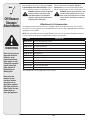
Leveling the Deck
NOTE: Check the tractor’s tire pressure before perform-
ing any deck leveling adjustments. Refer to Tires on
page 24 for information regarding tire pressure.
Front To Rear
The front of the cutting deck is supported by a stabilizer
bar that can adjusted to level the deck from front to rear.
The front of the deck should be between 1/4-inch and
3/8-inch lower than the rear of the deck. Adjust if
necessary as follows:
1. With the tractor parked on a firm, level surface, place
the deck lift lever in the top notch (highest position)
and rotate the blade nearest the discharge chute so
that it is parallel with the tractor.
2. Measure the distance from the front of the blade tip to
the ground and the rear of the blade tip to the ground.
The first measurement taken should be between
1/4” and 3/8” less than the second measurement.
Determine the approximate distance necessary for
proper adjustment and proceed, if necessary, to the
next step.
3. Locate the jam nut and lock nut on the front side of the
stabilizer bracket. See Fig. 5-1. After loosening the jam
nut:
Tighten the lock nut to raise the front of the deck;
Loosen the lock nut to lower the front of the deck.
4. Retighten the jam nut loosened earlier when proper
adjustment is achieved.
Side to Side
If the cutting deck appears to be mowing unevenly, a side
to side adjustment can be performed. Adjust if necessary
as follows:
1. With the tractor parked on a firm, level surface, place
the deck lift lever in the top notch (highest position)
and rotate both blades so that they are perpendicular
with the tractor.
2. Measure the distance from the outside of the left blade
tip to the ground and the distance from the outside of
the right blade tip to the ground. Both measurements
taken should be equal. If they’re not, proceed to the
next step.
3. Loosen, but do NOT remove, the hex cap screw on
the left deck hanger bracket. See Fig. 5-2.
4. Balance the deck by using a wrench to turn the
adjustment gear (found immediately behind the hex
cap screw just loosened) clockwise/up or counter-
clockwise/down. The deck is properly balanced when
both blade tip measurements taken earlier are equal.
5. Retighten the hex cap screw on the left deck hanger
bracket when proper adjustment is achieved.
5
Adjusting
Your Lawn
Tractor
Figure 5-2
Figure 5-1
WARNING
Never attempt to
make any adjust-
ments while the
engine is running,
except where speci-
fied in the operator’s
manual.
Page is loading ...
Page is loading ...
Page is loading ...
Page is loading ...
Page is loading ...
Page is loading ...
Page is loading ...
Page is loading ...
Page is loading ...
Page is loading ...
Page is loading ...
Page is loading ...
Page is loading ...
Page is loading ...
Page is loading ...
-
 1
1
-
 2
2
-
 3
3
-
 4
4
-
 5
5
-
 6
6
-
 7
7
-
 8
8
-
 9
9
-
 10
10
-
 11
11
-
 12
12
-
 13
13
-
 14
14
-
 15
15
-
 16
16
-
 17
17
-
 18
18
-
 19
19
-
 20
20
-
 21
21
-
 22
22
-
 23
23
-
 24
24
-
 25
25
-
 26
26
-
 27
27
-
 28
28
-
 29
29
-
 30
30
-
 31
31
-
 32
32
-
 33
33
-
 34
34
-
 35
35


Ask a question and I''ll find the answer in the document
Finding information in a document is now easier with AI