Page is loading ...

2019 Microchip Technology Inc. DS50002887A
EVB-USB7056
Evaluation Board
User’s Guide

DS50002887A-page 2 2019 Microchip Technology Inc.
Note the following details of the code protection feature on Microchip devices:
• Microchip products meet the specification contained in their particular Microchip Data Sheet.
• Microchip believes that its family of products is one of the most secure families of its kind on the market today, when used in the
intended manner and under normal conditions.
• There are dishonest and possibly illegal methods used to breach the code protection feature. All of these methods, to our
knowledge, require using the Microchip products in a manner outside the operating specifications contained in Microchip’s Data
Sheets. Most likely, the person doing so is engaged in theft of intellectual property.
• Microchip is willing to work with the customer who is concerned about the integrity of their code.
• Neither Microchip nor any other semiconductor manufacturer can guarantee the security of their code. Code protection does not
mean that we are guaranteeing the product as “unbreakable.”
Code protection is constantly evolving. We at Microchip are committed to continuously improving the code protection features of our
products. Attempts to break Microchip’s code protection feature may be a violation of the Digital Millennium Copyright Act. If such acts
allow unauthorized access to your software or other copyrighted work, you may have a right to sue for relief under that Act.
Microchip received ISO/TS-16949:2009 certification for its worldwide
headquarters, design and wafer fabrication facilities in Chandler and
Tempe, Arizona; Gresham, Oregon and design centers in California
and India. The Company’s quality system processes and procedures
are for its PIC
®
MCUs and dsPIC
®
DSCs, KEELOQ
®
code hopping
devices, Serial EEPROMs, microperipherals, nonvolatile memory and
analog products. In addition, Microchip’s quality system for the design
and manufacture of development systems is ISO 9001:2000 certified.
QUALITYMANAGEMEN TSY STEM
CER TIFIEDBYDNV
== ISO/TS16949==
Information contained in this publication regarding device applications and the like is provided only for your convenience and may be
superseded by updates. It is your responsibility to ensure that your application meets with your specifications. MICROCHIP MAKES NO
REPRESENTATIONS OR WARRANTIES OF ANY KIND WHETHER EXPRESS OR IMPLIED, WRITTEN OR ORAL, STATUTORY OR
OTHERWISE, RELATED TO THE INFORMATION, INCLUDING BUT NOT LIMITED TO ITS CONDITION, QUALITY, PERFORMANCE,
MERCHANTABILITY OR FITNESS FOR PURPOSE. Microchip disclaims all liability arising from this information and its use. Use of Micro-
chip devices in life support and/or safety applications is entirely at the buyer’s risk, and the buyer agrees to defend, indemnify and hold
harmless Microchip from any and all damages, claims, suits, or expenses resulting from such use. No licenses are conveyed, implicitly or
otherwise, under any Microchip intellectual property rights unless otherwise stated.
Trademarks
The Microchip name and logo, the Microchip logo, AnyRate, AVR, AVR logo, AVR Freaks, BitCloud, chipKIT, chipKIT logo, CryptoMemory,
CryptoRF, dsPIC, FlashFlex, flexPWR, Heldo, JukeBlox, KeeLoq, Kleer, LANCheck, LINK MD, maXStylus, maXTouch, MediaLB, megaAVR,
MOST, MOST logo, MPLAB, OptoLyzer, PIC, picoPower, PICSTART, PIC32 logo, Prochip Designer, QTouch, SAM-BA, SpyNIC, SST, SST
Logo, SuperFlash, tinyAVR, UNI/O, and XMEGA are registered trademarks of Microchip Technology Incorporated in the U.S.A. and other
countries.
ClockWorks, The Embedded Control Solutions Company, EtherSynch, Hyper Speed Control, HyperLight Load, IntelliMOS, mTouch, Precision
Edge, and Quiet-Wire are registered trademarks of Microchip Technology Incorporated in the U.S.A.
Adjacent Key Suppression, AKS, Analog-for-the-Digital Age, Any Capacitor, AnyIn, AnyOut, BodyCom, CodeGuard, CryptoAuthentication,
CryptoAutomotive, CryptoCompanion, CryptoController, dsPICDEM, dsPICDEM.net, Dynamic Average Matching, DAM, ECAN, EtherGREEN,
In-Circuit Serial Programming, ICSP, INICnet, Inter-Chip Connectivity, JitterBlocker, KleerNet, KleerNet logo, memBrain, Mindi, MiWi,
motorBench, MPASM, MPF, MPLAB Certified logo, MPLIB, MPLINK, MultiTRAK, NetDetach, Omniscient Code Generation, PICDEM,
PICDEM.net, PICkit, PICtail, PowerSmart, PureSilicon, QMatrix, REAL ICE, Ripple Blocker, SAM-ICE, Serial Quad I/O, SMART-I.S., SQI,
SuperSwitcher, SuperSwitcher II, Total Endurance, TSHARC, USBCheck, VariSense, ViewSpan, WiperLock, Wireless DNA, and ZENA are
trademarks of Microchip Technology Incorporated in the U.S.A. and other countries.
SQTP is a service mark of Microchip Technology Incorporated in the U.S.A.
Silicon Storage Technology is a registered trademark of Microchip Technology Inc. in other countries.
GestIC is a registered trademark of Microchip Technology Germany II GmbH & Co. KG, a subsidiary of Microchip Technology Inc., in other
countries.
All other trademarks mentioned herein are property of their respective companies.
© 2019, Microchip Technology Incorporated, All Rights Reserved.
ISBN: 978-1-5224-4535-7

EVB-USB7056
EVALUATION BOARD
USER’S GUIDE
2019 Microchip Technology Inc. DS50002887A-page 3
Table of Contents
Preface ........................................................................................................................... 5
Introduction............................................................................................................ 5
Document Layout .................................................................................................. 5
Conventions Used in this Guide ............................................................................ 6
The Microchip Web Site ........................................................................................ 7
Development Systems Customer Change Notification Service ............................ 7
Customer Support ................................................................................................. 7
Document Revision History ................................................................................... 8
Chapter 1. Overview
1.1 General Introduction to USB7056 .................................................................. 9
1.2 EVB-USB7056 Overview .............................................................................. 10
1.3 References ................................................................................................... 11
1.4 Acronyms and Definitions ............................................................................. 12
Chapter 2. Getting Started
2.1 Introduction ................................................................................................... 13
2.2 Board Contents ............................................................................................ 13
2.3 Quick Start .................................................................................................... 13
2.3.1 Power Source ............................................................................................ 13
2.3.2 CFG_STRAP1 Jumper .............................................................................. 13
2.3.3 Default Firmware ....................................................................................... 13
2.3.4 Host Connection ........................................................................................ 14
2.3.5 Downstream Port Connections .................................................................. 14
Chapter 3. Hardware Configuration
3.1 Hardware Configuration Options .................................................................. 15
3.1.1 Configuration ............................................................................................. 15
3.1.2 Power Source ............................................................................................ 18
3.1.3 Board Power .............................................................................................. 18
3.1.4 Reset ......................................................................................................... 19
3.1.5 USB Ports .................................................................................................. 20
3.1.6 DisplayPort Alternate Mode ....................................................................... 21
3.1.7 ‘PM-PD’ Plug-in Power Delivery Module ................................................... 21
3.1.8 Spare GPIOs ............................................................................................. 22
3.1.9 USB-to-SMBus/I
2
C Master ........................................................................ 22
3.1.10 USB-to-I2S .............................................................................................. 23
3.1.11 LED Indicators ......................................................................................... 23
3.1.12 Switches .................................................................................................. 24
3.1.13 Connector Descriptions ........................................................................... 24
3.1.14 Test Points .............................................................................................. 26

EVB-USB7056 Evaluation Board User’s Guide
DS50002887A-page 4 2019 Microchip Technology Inc.
Appendix A. EVB-USB7056 Evaluation Board
A.1 Introduction .................................................................................................. 29
Appendix B. Schematics
B.1 Introduction .................................................................................................. 31
Appendix C. Bill of Materials
C.1 Introduction .................................................................................................. 43
Appendix D. Silk Screens
D.1 Introduction .................................................................................................. 49
Worldwide Sales and Service .....................................................................................52
NOTES:

EVB-USB7056
EVALUATION BOARD
USER’S GUIDE
2019 Microchip Technology Inc. DS50002887A-page 5
Preface
INTRODUCTION
This chapter contains general information that will be useful to know before using the
EVB-USB7056. Items discussed in this chapter include:
• Document Layout
• Conventions Used in this Guide
• The Microchip Web Site
• Development Systems Customer Change Notification Service
• Customer Support
• Document Revision History
DOCUMENT LAYOUT
This document describes how to use the EVB-USB7056 Evaluation Board as a
development tool for the USB7056 six-port USB smart hub controller. The manual
layout is as follows:
• Chapter 1. “Overview” – This shows a brief description of the EVB-USB7056
Evaluation Board.
• Chapter 2. “Getting Started” – This includes instructions on how to get started
with the EVB-USB7056 Evaluation Board.
• Chapter 3. “Hardware Configuration” – This provides information about the
EVB-USB7056 Evaluation Board battery charging features.
• Appendix A. “EVB-USB7056 Evaluation Board” – This appendix shows the
EVB-USB7056 Evaluation Board.
• Appendix B. “Schematics” – This appendix shows the EVB-USB7056 Evalua-
tion Board schematics.
NOTICE TO CUSTOMERS
All documentation becomes dated, and this manual is no exception. Microchip tools and
documentation are constantly evolving to meet customer needs, so some actual dialogs
and/or tool descriptions may differ from those in this document. Please refer to our web site
(www.microchip.com) to obtain the latest documentation available.
Documents are identified with a “DS” number. This number is located on the bottom of each
page, in front of the page number. The numbering convention for the DS number is
“DSXXXXXA”, where “XXXXX” is the document number and “A” is the revision level of the
document.
For the most up-to-date information on development tools, see the MPLAB
®
IDE online help.
Select the Help menu, and then Topics to open a list of available online help files.

EVB-USB7056 Evaluation Board User’s Guide
DS50002887A-page 6 2019 Microchip Technology Inc.
• Appendix C. “Bill of Materials” – This appendix includes the EVB-USB7056
Evaluation Board Bill of Materials (BOM).
• Appendix D. “Silk Screens” – This appendix shows the EVB-USB7056 Evalua-
tion Board silk screen images.
CONVENTIONS USED IN THIS GUIDE
This manual uses the following documentation conventions:
DOCUMENTATION CONVENTIONS
Description Represents Examples
Arial font:
Italic characters Referenced books MPLAB
®
IDE User’s Guide
Emphasized text ...is the only compiler...
Initial caps A window the Output window
A dialog the Settings dialog
A menu selection select Enable Programmer
Quotes A field name in a window or
dialog
“Save project before build”
Underlined, italic text with
right angle bracket
A menu path File>Save
Bold characters A dialog button Click OK
A tab Click the Power tab
N‘Rnnnn A number in verilog format,
where N is the total number of
digits, R is the radix and n is a
digit.
4‘b0010, 2‘hF1
Text in angle brackets < > A key on the keyboard Press <Enter>, <F1>
Courier New font:
Plain Courier New Sample source code #define START
Filenames autoexec.bat
File paths c:\mcc18\h
Keywords _asm, _endasm, static
Command-line options -Opa+, -Opa-
Bit values 0, 1
Constants 0xFF, ‘A’
Italic Courier New A variable argument file.o, where file can be
any valid filename
Square brackets [ ] Optional arguments mcc18 [options] file
[options]
Curly brackets and pipe
character: { | }
Choice of mutually exclusive
arguments; an OR selection
errorlevel {0|1}
Ellipses... Replaces repeated text var_name [,
var_name...]
Represents code supplied by
user
void main (void)
{ ...
}

Preface
2019 Microchip Technology Inc. DS50002887A-page 7
THE MICROCHIP WEB SITE
Microchip provides online support via our web site at www.microchip.com. This web
site is used as a means to make files and information easily available to customers.
Accessible by using your favorite Internet browser, the web site contains the following
information:
• Product Support – Data sheets and errata, application notes and sample
programs, design resources, user’s guides and hardware support documents,
latest software releases and archived software
• General Technical Support – Frequently Asked Questions (FAQs), technical
support requests, online discussion groups, Microchip consultant program
member listing
• Business of Microchip – Product selector and ordering guides, latest Microchip
press releases, listing of seminars and events, listings of Microchip sales offices,
distributors and factory representatives
DEVELOPMENT SYSTEMS CUSTOMER CHANGE NOTIFICATION SERVICE
Microchip’s customer notification service helps keep customers current on Microchip
products. Subscribers will receive e-mail notification whenever there are changes,
updates, revisions or errata related to a specified product family or development tool of
interest.
To register, access the Microchip web site at www.microchip.com, click on Customer
Change Notification and follow the registration instructions.
The Development Systems product group categories are:
• Compilers – The latest information on Microchip C compilers, assemblers, linkers
and other language tools. These include all MPLAB C compilers; all MPLAB
assemblers (including MPASM assembler); all MPLAB linkers (including MPLINK
object linker); and all MPLAB librarians (including MPLIB object librarian).
• Emulators – The latest information on Microchip in-circuit emulators.This
includes the MPLAB REAL ICE and MPLAB ICE 2000 in-circuit emulators.
• In-Circuit Debuggers – The latest information on the Microchip in-circuit
debuggers. This includes MPLAB ICD 3 in-circuit debuggers and PICkit 3 debug
express.
• MPLAB IDE – The latest information on Microchip MPLAB IDE, the Windows
Integrated Development Environment for development systems tools. This list is
focused on the MPLAB IDE, MPLAB IDE Project Manager, MPLAB Editor and
MPLAB SIM simulator, as well as general editing and debugging features.
• Programmers – The latest information on Microchip programmers. These include
production programmers such as MPLAB REAL ICE in-circuit emulator, MPLAB
ICD 3 in-circuit debugger and MPLAB PM3 device programmers. Also included
are nonproduction development programmers such as PICSTART Plus and
PIC-kit 2 and 3.
CUSTOMER SUPPORT
Users of Microchip products can receive assistance through several channels:
• Distributor or Representative
• Local Sales Office
• Field Application Engineer (FAE)
• Technical Support

EVB-USB7056 Evaluation Board User’s Guide
DS50002887A-page 8 2019 Microchip Technology Inc.
Customers should contact their distributor, representative or field application engineer
(FAE) for support. Local sales offices are also available to help customers. A listing of
sales offices and locations is included in the back of this document.
Technical support is available through the web site at:
http://www.microchip.com/support
DOCUMENT REVISION HISTORY
Revisions Section/Figure/Entry Correction
DS50002887A
(05-21-19)
Initial release

EVB-USB7056
EVALUATION BOARD
USER’S GUIDE
2019 Microchip Technology Inc. DS50002887A-page 9
Chapter 1. Overview
1.1 GENERAL INTRODUCTION TO USB7056
The USB7056 hub controller is a six-port SuperSpeed smart hub controller with USB
Power Delivery (PD) support. It is fully compliant with the USB3.1, USB2.0, and USB
PD 3.0 specifications. The six-port hub supports 5 Gbps SuperSpeed (SS USB3.1
Gen1), 480 Mbps High-Speed (HS), 12 Mbps Full-Speed (FS), and 1.5 Mbps
Low-Speed (LS) USB signaling.
The USB7056 has one USB3.1 Gen1 upstream port with PD and DisplayPort
Alternate Mode support. PD support is enabled through a companion PD controller
(UPD350), which operates as a PD PHY + MAC + GPIO expander. The PD firmware
stack executes within the USB7056 hub’s internal microcontroller (MCU). The
DisplayPort Alternate Mode support is enabled through the use of an external 6:4
cross-bar switch. The USB7056 firmware supports up to 100W of power delivery on the
upstream port.
Note: The EVB-USB7056 baseboard supports up to 100W of power delivery by
design. However, the included power regulator is limited to 60W maximum
capability. The default hub firmware load is hence also configured by default
to offer 60W maximum to the device attached to the upstream USB Type-C
PD port. The PD power regulator (abbreviated as PM-PD) is a plug-in daugh-
ter card, which can be exchanged to test with various DC/DC solutions. Dif-
ferent PM-PD solutions may extend or restrict the maximum power capability
depending upon the capabilities of the individual daughter card, and the hub
firmware load should be reconfigured accordingly when exchanging PM-PD
daughter cards.
The USB7056 has one basic USB3.1 Gen1 downstream USB Type-C port (up to 15W,
no PD), three USB3.1 Gen1 downstream ports, and two USB2.0 downstream Type-A
ports. All downstream ports support battery charging. On these battery charging
enabled downstream ports, the device provides automatic USB data line handshaking.
The handshaking supports USB BC1.2 Charging Downstream Port (CDP), Dedicated
Charging Port (DCP), and legacy devices.
The USB7056 is a smart hub with an embedded MCU for enabling advanced features.
These features include hub configuration through the upstream USB interface,
USB-to-I
2
C bridging, USB-to-SPI bridging, USB-to-GPIO bridging, USB-to-I
2
S audio
bridging, and more.

EVB-USB7056 Evaluation Board User’s Guide
DS50002887A-page 10 2019 Microchip Technology Inc.
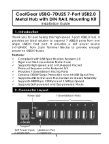
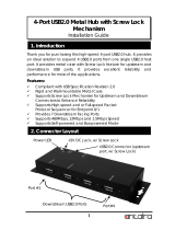
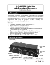
1.2 EVB-USB7056 OVERVIEW
Figure 1-1 shows an image of the EVB-USB7056.
FIGURE 1-1: EVB-USB7056 EVALUATION BOARD
The EVB-USB7056 board is a six-layer RoHS-compliant evaluation board that utilizes
the USB7056 to provide a fully functional six-port hub with battery charging capabilities.
The EVB-USB7056 also features the UCS2114 two-channel USB port power controller.
The USB7056 is configured to execute firmware from an external SST26VF016B SPI
Flash device (U10). Many configurable options may be controlled through on-board
jumper options or modified through the MPLAB
®
Connect Configurator tool. To allow
maximum operational flexibility, all Programmable Function (PFx) pins are accessible
through PCB headers. The EVB-USB7056 demonstrates driver compatibility with
native Microsoft
®
Windows
®
, Mac OS
®
, and Linux
®
hub drivers.
The EVB-USB7056 provides the following features:
• One USB7056 in a 100-pin QFN RoHS-compliant package
• One UPD350 in a 28-pin QFN RoHS-compliant package
• Three UCS2114 in a 20-pin QFN RoHS-compliant package
• One SST26VF016B in an 8-pin SOIC RoHS-compliant package
• USB2.0 compliant (HS, FS, and LS operation) and 5V-tolerant USB pins
• One USB3.1 Gen 1 upstream hub port that can source up to 60W (extendable up
to 100W with capable PM-PD daughter card) USB PD and DisplayPort Alternate
Mode support (pinout modes C and D)
• Self-powered operation
• One USB3.1 Gen 1 basic 15W USB Type-C downstream port (no PD)
• Three USB3.1 Gen 1 Type-A downstream ports
• Two USB2.0 Type-A downstream ports
• Battery Charging support (BC1.2 CDP and DCP) on all downstream ports
• Support for individual port power and overcurrent sense on all downstream ports
• Wide input supply range (12V-24V supported on baseboard, 24V required for
default supplied PM-PD)
• DSC1001 25 MHz oscillator
• MCP1825 on-board +3.3V, 1A regulator

Overview
2019 Microchip Technology Inc. DS50002887A-page 11
• MIC23201 single on-board +1.2V, 1A regulator
• MCP19035 on-board +5.0V, 6A switching regulator module
• +5.0V, +3.3V, and +VDD Core LED indicators
• LED voltage meter on upstream PD port for monitoring VBUS voltage
• Port power LED indicator for each downstream port VBUS
• Reset, SPI Chip Activity, and DisplayPort HPD LED indicator
• Optional GPIO LED drivers for development and debug use
• External Programmable Function (PFx/GPIOx) pin headers
• Battery Charging and Non Removable strap selection header
• Configuration mode selection headers
• Optional I
2
S daughter card for exercising USB-to-I
2
S feature (not included)
Figure 1-2 shows the block diagram of the EVB-USB7056.
1.3 REFERENCES
Concepts and materials available in the following documents may be helpful when
reading this document. Visit www.microchip.com for the latest documentation.
• USB7056 Data Sheet
• AN2810 - Configuration of USB7002/705x
FIGURE 1-2: EVB-USB7056 BLOCK DIAGRAM
DS Port 1 DS Port 2 DS Port 3 DS Port 4 DS Port 5 DS Port 6
UCS
2114
UCS
2114
UCS
2114
USB7056
US Port 0
SPI
Flash
Headers
Source
Crossbar Mux DP Redriver
DP 1.3
DP 1.3
USB3.1
USB3.1
USB3.1
USB3.1
USB3.1
USB2.0
USB2.0
USB2.0
USB2.0
USB2.0
USB2.0
USB2.0
DP AUX
SPI
I2S
UPD350
CC1/CC2
PM-PD
VIN
MCP19035
5.0V
MCP1825
MIC23201
3.3V
1.2V
VBUS
VBUS VBUSVBUS
USB3.1
GPIO/I2C
DisplayPort

EVB-USB7056 Evaluation Board User’s Guide
DS50002887A-page 12 2019 Microchip Technology Inc.
1.4 ACRONYMS AND DEFINITIONS
TABLE 1-1: ACRONYMS AND DEFINITIONS
Acronym Definition
BC1.2 Latest USB-IF-specified USB battery charging standard
CDP
Charging Downstream Port. A type of port defined in the BC1.2
specification that is capable of delivering up to 1.5A of charging at
5V along with USB data.
DCP
Dedicated Charging Port. A type of port defined in the BC1.2 spec-
ification that is capable of delivering up to 1.5A of charging at 5V
without USB data capabilities.
DFP
Downstream Facing Port. On a hub, this is the port where the
device should be attached to.
DP
DisplayPort, an interface used to connect transit display and sound
data from a video-capable device to a monitor or display.
EVB Evaluation Board
Gen1 USB 3.1 Specification 5 Gbps data rate speed
IC Integrated Circuit
OTP One-Time Programmable memory
PD USB Power Delivery Specification
PM-PD USB Power Delivery DC/DC plug in VBUS Supply daughter card
SDP
Standard Downstream Port. A type of port defined in the BC1.2
specification that is capable of delivering up to 500 mA of charging
at 5V along with USB data.
Type-A Non-reversible USB connector, used for DFP ports only
Type-C Reversible USB Connector
USB2.0
USB Specification version 2.0. An industry standard for cables,
connectors, and protocol maintained by the USB-IF.
USB3.1
USB Specification version 3.1. An industry standard for cables,
connectors, and protocol maintained by the USB-IF.
USB
Universal Serial Bus, a communication technology specification
developed by the USB-IF.
USB-IF
USB Integrators Forum, a collection of corporate sponsored mem-
bers responsible for developing USB specifications
UFP
Upstream Facing Port. On a hub, this is the port where the USB
host should be attached to.
VBUS
Refers to the 5V-20V power conductor inside of a Type-C cable,
the power pins on a USB connector, or the USB power traces on a
PCB.

EVB-USB7056
EVALUATION BOARD
USER’S GUIDE
2019 Microchip Technology Inc. DS50002887A-page 13
Chapter 2. Getting Started
2.1 INTRODUCTION
The Microchip EVB-USB7056 is designed for flexible configuration solutions. It can be
configured via the default internal register settings, via a downloadable external firm-
ware to an on-board SPI Flash, via SMBus, or via the on-board jumper options. When
configured with the default, preloaded SPI Flash firmware, the device operates as a
USB3.1 Gen1 hub with a Type-C upstream port supporting USB PD, one downstream
USB3.1 Gen1 Type-C port, three downstream USB3.1 Gen1 Type-A ports, and two
downstream USB2.0 Type-A ports. The upstream port supports DisplayPort Alternate
Mode and up to 60W of power sourcing to the attached PD-capable host.
Microchip provides a comprehensive software programming tool, MPLAB Connect
(MPLABC), for configuring USB7056 functions, registers, and OTP memory. USB7056
requires MPLABC version 2.1.0 or greater.
For additional information on the MPLABC programming tool, refer to Software Librar-
ies within the Microchip USB7056 product page at www.microchip.com/USB7056.
2.2 BOARD CONTENTS
The EVB-USB7056 Evaluation Board includes the basic equipment necessary for eval-
uation. The items included in the board are:
• EVB-USB7056
• ‘PM-PD’ Power Module (premounted to the EVB)
• Type-C-to-Type-C USB cable
2.3 QUICK START
2.3.1 Power Source
A power supply is not included with the EVB-USB7056. Connect a 24V (minimum 75W
is recommended) power supply to the J5 terminal block.
2.3.2 CFG_STRAP1 Jumper
A shunt must be installed on only one of the CFG_STRAP1 options on J9. Any one of
the settings may be selected. Refer to the data sheet for the option that most closely
matches the feature set desired.
2.3.3 Default Firmware
A firmware is loaded by default onto the on-board SPI Flash, and, hence, programming
the SPI Flash before operating the EVB is unnecessary. The D12 LED indicator illumi-
nates bright blue while the hub is executing the firmware from the external SPI Flash.
Note: If it is preferred to run from the internal hub ROM firmware image, install a
shunt on J12 to disable access to the SPI Flash device. PD functionality is
not supported when running the firmware from the internal hub ROM firm-

EVB-USB7056 Evaluation Board User’s Guide
DS50002887A-page 14 2019 Microchip Technology Inc.
ware image. This mode of operation should only be used for debugging or
for loading a new firmware image to the SPI Flash. (The shunt should be
removed right before loading the new firmware image to the SPI Flash.)
2.3.4 Host Connection
A USB2.0 or USB3.1 host must be connected to the upstream Type-C port J2.
If connecting the hub to a Type-A host port, use a USB Type-A-to-Type-C cable. Note
that advanced functionality enabled through USB PD cannot function when using a
Type-A-to-Type-C adapter cable.
If connecting the hub to a Type-C host port, use a USB-IF-certified cable that supports
USB3.1 data protocol to ensure the highest functionality is supported by the cable. If
the host supported Power Delivery and requests power from the EVB-USB7056, the
negotiated voltage can be observed by monitoring the VBUS diode voltmeter on
D25-D28. If the host also supports DisplayPort Alternate Mode, then a display may
optionally connected to the EVB-USB7056 via a DisplayPort cable connected to J31.
Note: Charge-only Type-C cables with missing USB data wires (either missing
USB3.1 wires only or missing both USB2 and USB3.1 wires) do exist.
Always ensure to use USB-IF certified, known good cables when testing with
the EVB-USB7056.
2.3.5 Downstream Port Connections
Once host connection is established on the upstream host port, devices may be con-
nected to the downstream ports to begin operating with the USB host. The downstream
port VBUS LEDs may be used to verify that power is properly applied to the down-
stream ports. Failure to illuminate indicates either a host connection failure (VBUS is
enabled by the hub only when a command is received from the USB host) or a possible
overcurrent condition on the downstream port.

EVB-USB7056
EVALUATION BOARD
USER’S GUIDE
2019 Microchip Technology Inc. DS50002887A-page 15
Chapter 3. Hardware Configuration
3.1 HARDWARE CONFIGURATION OPTIONS
Figure 3-1 shows the top view of EVB-USB7056.
FIGURE 3-1: EVB-USB7056 (TOP VIEW)
3.1.1 Configuration
3.1.1.1 CFG_STRAP1
The J9 2x6 header allows for different options to be selected for the CFG_STRAP1
configuration strap. In the standard firmware offering, only options 1 and 2 are sup-
ported. A shunt must be installed in either option 1 (J9, pins 1-2) or option 2 (J9, pins
3-4).
The CFG_STRAP1 option 1 special features are:
• USB-to-SMBus/I
2
C master bridge interface
• SMBus/I
2
C slave interface
The CFG_STRAP1 option 2 special features are:
• USB-to-SMBus/I
2
C master bridge interface
• USB-to-I
2
S audio interface

EVB-USB7056 Evaluation Board User’s Guide
DS50002887A-page 16 2019 Microchip Technology Inc.
3.1.1.2 EXTERNAL SPI FLASH
The EVB-USB7056 requires an external firmware image loaded to the on-board SPI
Flash. The external SPI Flash firmware is required to support USB PD functionality. The
EVB-USB7056 is shipped with a firmware image preloaded to the on-board memory.
The firmware revision can be quickly identified by enumerating the EVB-USB7056 to a
USB host PC and inspecting the USB Device ID (bcdDevice) of the USB2.0 or USB3.1
hub.
To properly boot from the SPI Flash, the following conditions must be met:
• Shunts are installed on J15 across pins 1-2 and 4-5.
• Any shunt installed on J12 is removed.
• A valid firmware image is loaded onto the SPI Flash device.
FIGURE 3-2: COMPONENTS CRITICAL FOR EXTERNAL SPI FLASH
FIRMWARE EXECUTION
The recommended sequence for reprogramming the SPI firmware is:
1. Install a shunt onto J12 to force booting from the internal ROM memory.
2. Reset the USB7056.
3. Connect the EVB-USB7056 to a USB host PC with a USB Type-A-to-Type-C
cable.
4. Boot the MPLAB Connect software and select the new firmware image.
5. Remove the shunt on J12.
6. Click the program button on MPLAB Connect.
3.1.1.3 INTERNAL ROM FIRMWARE
A basic hub firmware is included within the USB7056 internal ROM memory that may
be used as a boot-ROM for loading new firmware images into the external SPI Flash.
When the firmware is run from the internal ROM memory, the USB7056 basic hub fea-
tures will function, but the USB PD features will be non-functional. A USB
Type-A-to-Type-C adapter cable is recommended when running in this mode to ensure
that the attached host can reliably detect the USB hub and communicate with it.
SPI/Strap
Select (J15)
SPI Activity
LED (D12)

Hardware Configuration
2019 Microchip Technology Inc. DS50002887A-page 17
To force the hub to boot from the internal ROM, install a shunt to J12 as shown in
Figure 3-3. When the firmware is run from the internal ROM memory, the CFG_BC_EN
and CFG_NON_REM configuration straps will also function, and the shunts installed to
J15 should also be moved to short pins 2-3 and 5-6 for these strap configuration
options to be sampled by the hub.
FIGURE 3-3: COMPONENTS CRITICAL FOR INTERNAL ROM FIRMWARE
EXECUTION
3.1.1.3.1 BC Strap Select Jumper
A shunt must be installed on only one of the CFG_BC_EN BC1.2 battery charging strap
options on J16. Select J16[1-2] to enable BC1.2 battery charging DCP and CDP on all
downstream ports. Select J16[2-3] to disable BC1.2 battery charging on all down-
stream ports.
Note: If a different combination of battery charging enable/disable is desired than
what is available on J16, select J16[2-3] to disable battery charging on all
ports, and then configure the hub via the MPLAB Connect Configurator tool
to enable battery charging support on only the desired subset of downstream
ports.
3.1.1.3.2 Non-Removable Port Strap Select Jumper
A shunt must be installed on only one of the CFG_NON_REM non-removable port
strap options on J18. Select J18[1-2] to set all downstream ports as non-removable.
Select J18[2-3] to set all downstream ports as removable.
Note 1: If unsure with how USB non-removable port option works, it is recom-
mended to select J18[2-3] to set all downstream ports as removable. This
setting is just used as a reporting mechanism to describe the system to the
host; the hub behavior is unchanged by changing this setting.
2: If a different combination of battery charging enable/disable is desired than
what is available on J18, select J18[2-3] to set all downstream ports as
removable, and then configure the hub via the MPLAB Connect Configu-
rator tool to set only the desired subset of downstream ports as
non-removable.
SPI/Strap
Select (J15)
Install shunt
to force
boot from
ROM (J12)
Install
shunts to
select strap
options
(J16+J18)

EVB-USB7056 Evaluation Board User’s Guide
DS50002887A-page 18 2019 Microchip Technology Inc.
3.1.1.4 SMBUS/I
2
C SLAVE
An SMBus/I
2
C slave interface is available for hub configuration in CFG_STRAP1 mode
2 only. Configuration via SMBus/I
2
C slave interface may be performed in both external
SPI Flash or internal ROM memory firmware execution options. Pull-up resistors must
be sensed by the hub at power-on in order for the SMBus/I
2
C slave interface to be
active. If both SDA and SCL are not sensed as high upon power-on/reset, the
SMBus/I
2
C slave interface is disabled on the hub. Install a shunt across J28. The loca-
tions of these headers are shown in Figure 3-4.
FIGURE 3-4: SMBUS/I
2
C SLAVE HEADER LOCATIONS
3.1.2 Power Source
The EVB-USB7056 must be powered externally through the J1 four-pin DIN connector,
or through the J5 terminal block.
The supported input voltage range for the baseboard is 12V to 24V. By default, the sup-
plied PM-PD requires an input of 24V to properly regulate up to 20V to the upstream
PD ports. The recommended input voltage is 24V unless an alternate PM-PD, a spe-
cialized hub firmware, or both are used.
A power supply is not included with the EVB-USB7056.
3.1.3 Board Power
The board includes LED indicators to indicate if all board power nets are working and
includes test loops for quick measurements. The location of these LEDs and test loops
are shown in Figure 3-5.
PF26 – Clock
(J23-1)
PF27 – Data
(J23-3)
GND
(J23-2)
Install shunt to
enable pull-up
resistors (J28)

Hardware Configuration
2019 Microchip Technology Inc. DS50002887A-page 19
FIGURE 3-5: BOARD POWER LEDS AND TEST LOOPS
3.1.4 Reset
An on-board reset button is included which resets the USB7056 when pressed. A reset
header (J11) is also included, which holds the USB7056 in reset when a shunt is
installed across the header. A red LED indicator also illuminates when the reset signal
is asserted (active low). The locations of these components are shown in Figure 3-6.
FIGURE 3-6: RESET BUTTON LOCATION
5V LED Indicator
(D15)
3.3V LED Indicator
(D18)
1.2V LED Indicator
(D19)
GND Test Loop
(TP21)
5V Test Loop
(TP22)
3.3V Test Loop
(TP23)
1.2V Test Loop
(TP25)
Reset LED
(D11)
Reset Header
(J10)
Reset button
(SW2)

EVB-USB7056 Evaluation Board User’s Guide
DS50002887A-page 20 2019 Microchip Technology Inc.
3.1.5 USB Ports
The following is a list of capabilities for each USB port on the EVB-USB7056:
• Port 0:
- Data Upstream Port (connects to a USB host or a hub DFP)
- USB3.1 Type-C receptacle
- USB3.1 Gen1 and USB2.0 data connectivity
- USB PD supporting up to 100W of power (depending on the PM-PD included)
- DisplayPort Alternate Mode supporting up to four lanes at DP v1.3 speeds
• Port 1:
- Data Downstream Port (connects to a USB device or a hub UFP)
- USB3.1 Type-C receptacle
- USB3.1 Gen1 and USB2.0 data connectivity
- Basic USB-C charging at up to 15W (5V at 3A)
• Ports 2, 3, and 4:
- Data Downstream Port (connects to a USB device or a hub UFP)
- USB3.1 Type-A receptacle
- USB3.1 Gen1 and USB2.0 data connectivity
- BC1.2 charging at up to 7.5W (5V at 1.5A) if BC is enabled in hub configura-
tion
• Ports 5 and 6:
- Data Downstream Port (connects to a USB device or a hub UFP)
- USB2.0 Type-A receptacle
- USB2.0 data connectivity
- BC1.2 charging at up to 7.5W (5V at 1.5A) if BC is enabled in hub configura-
tion
Figure 3-7 shows the USB ports of EVB-USB7056.
FIGURE 3-7: EVB-USB7056 USB PORTS
Port 4
Port
0
Port 1
Port 5
Port 2 Port 3 Port 6
/