Page is loading ...

Replacement Kits
MMR 1/4 Turn P/N 10058890
Firehawk P/N 10059031
Removing the Component Housing Assembly from the Ultra
Elite Facepiece
1. Remove the adapter assembly and the component housing
cover.
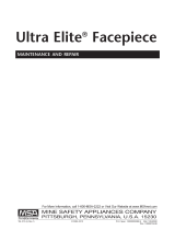
2. Using a small Phillips screwdriv-
er, remove the component hous-
ing ring screw. Grasp the ring
with the thumb and forefinger of
each hand. Gently spread the
ring halves apart at the bottom.
3. When the facepiece rubber is out of the ring groove, lift the
ring up away from the facepiece. The housing may need
pulled down slightly to allow enough room to remove the
ring from between the housing and the lower lens ring.
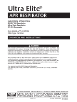
4. Remove the facepiece rubber
from the component housing
and pull the housing and nose-
cup (if installed) out of the face-
piece.
5. Do not discard the old component housing,
ClearCommand® Voicemitter Assembly and Retainer (if so
equipped), or the nosecup (if so equipped).
Removing the Inlet Valve Disc from the Spider Valve Gasket
1. Pull the spider valve gasket out of the OLD component
housing assembly. Ensure the white inlet disc valve remains
attached to the spider valve gasket.
2. Hold the spider valve gasket in one hand.
3. Using the other hand, gently fold the white inlet valve disc in
half and pull slightly to remove the inlet valve disc from the
stem at the center of the spider valve gasket.
4. Set the inlet valve disc aside on a clean, dry surface.
5. Inspect the inlet valve disc for any damage, tears, debris
etc. Use only an undamaged inlet valve disc.
Preparing the Replacement Kit for Installation
1. Pull the spider valve gasket out of the new component
housing assembly.
2. Gently stretch the center hole of the inlet disc valve over
and onto the new spider valve gasket stem.
3. With the pull-tab facing outward, reinsert the spider valve
gasket with inlet valve disc into the facepiece at an angle so
that the groove around the outer edge captures the housing
rim. The lower lip of the spider valve gasket must be com-
pletely under the rim in the component housing.
Note: The spider valve gasket may need bent slightly to work
the lip under the rim all the way around. When installed correct-
ly, the spider valve gasket will lay flat in the housing and none of
the spokes will be bent.
Replacing the Voicemitter Assembly for Facepieces
Equipped With the ClearCommand Communications System
1. Unscrew and remove the voicemitter assembly retaining ring
on the old component housing.
2. Turn the facepiece upside down and shake out the metal
voicemitter and gasket assembly.
3. Check the voicemitter and gasket assembly for damage.
Replace it if it is worn or damaged.
4. Be sure that the gasket is on the voicemitter assembly.
5. Place the voicemitter assembly into the retaining ring. Be
sure that the gasket side of the voicemitter is facing the
component housing.
6. Replace the retaining ring onto the new component housing
and hand-tighten.
Installing the Replacement Kit
(New Component Housing Assembly)
1. Slide the housing into the front of the facepiece.
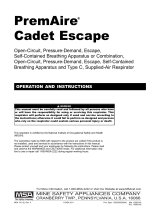
2. Starting at the top (narrow end)
of the housing, place the housing
in the facepiece groove. Work the
rubber all the way around the
housing. Check that the housing
is completely captured inside the
groove and the center-lines are
lined up.
3. Moisten the facepiece housing area and the inside of the
housing ring.
4. Insert the narrow end of the ring into the space between the
lower lens ring and the facepiece housing area.
5. Line up the component housing
ring mark with the facepiece cen-
terline.
6. Starting at the top, work the housing ring down on the face-
piece to capture the facepiece rubber in the ring groove.
Work your way down each side of the ring until the face-
piece rubber is completely captured inside the ring.
Ultra Elite
®
Facepiece Component Housing
Kit, Less Inlet Valve Disc
Installation Instructions

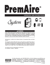
7. Gently squeeze the ring halves
together at the bottom of the
housing. Watch the facepiece
rubber at the top as you do this.
If you see any bulges or wrinkles
in the facepiece rubber, it is not
captured in the groove. Rework
the ring around the facepiece
rubber until there are no bulges
or wrinkles.
Bulges or wrinkles indicate the facepiece rubber is not seat-
ed correctly in the ring. Re-install the ring to seat it correct-
ly. Failure to follow this warning can cause the facepiece to
leak and result in serious personal injury or death.
8. When the housing ring appears to be seated, grasp the out-
side of the ring and the inside of the housing at the top
between your thumb and forefinger and squeeze them togeth-
er. Then do the same with the ring halves at the bottom.
9. Install the screw and tighten using a small Phillips screw-
driver.
Reassembling the Ultra Elite Component Housing Cover and
Adapter
For 1/4 Turn MMR facepieces:
1. Holding the adapter assembly in one hand, rotate the slip
nut so that the octagon flange on the slip nut lines up with
the octagon flange on the adapter.
2. Thread the adapter assembly into the facepiece.
3. Using a torque wrench with the spanner wrench (PN
494261), torque the adapter to a minimum 12 in.lbs. If nec-
essary, continue to torque until the top flat on the octagon is
horizontal with a maximum torque of 27 in.lbs.
4. The bayonets must be in a horizontal orientation. If the bay-
onets are not horizontal, remove the adapter assembly and
turn the slip nut to the next octagon flange alignment.
5. Re-install the adapter assembly so that the bayonets are hor-
izontal when the adapter assembly is torqued 12-27 in.lbs.
6. Place the component housing cover over the adapter
assembly. Tilt and rotate the cover to work it over one bayo-
net at a time.
7. Insert the tab on the cover into the slot in the lens ring.
8. Press in on the front of the cover until the cover hook snaps
in place.
9. Install the locking ring by sliding it into the groove on the
adapter. (Do not slide it into the space between the slip nut
flange and the adapter flange.)
10. Place the neckstrap brackets and the spacers in the cover
sockets under the locking ring.
11. Install the Phillips screws and tighten.
12. Verify each of the following features.
a. The adapter bayonets are locked into a horizontal position
and CANNOT be rotated.
b. The slip nut is threaded completely into the facepiece and
locked securely. It CANNOT be rotated.
c. The metal locking ring is locked into position and CAN-
NOT be rotated.
d. There is no loose play in the assembly of parts.
For Firehawk slide-to-connect facepieces:
1. Thread the adapter into the facepiece.
2. Tighten the adapter hand tight. Use the component housing
cover to continue to tighten until the top flat on the octagon
aligns with the two index marks at the top of the component
housing inlet.
3. Insert the tab on the component housing cover into the slot
in the lens ring.
4. Press in on the front of the cover until the cover hook snaps
in place.
5. Place the neckstrap brackets in the cover sockets.
6. Install and tighten the Phillips screws.
7. Verify that there is no loose play in the assembly of parts.
For Firehawk push-to-connect (PTC) facepieces:
1. Insert the component housing cover tab into the lens ring
slot, leave the cover loose.
2. Place the PTC adapter through the facepiece component
housing cover and thread the adapter assembly into the
facepiece hand tight.
3. Continue to tighten until the top flat of the adapter octagon
is horizontal.
Note: The octagon flats on the facepiece adapter must align
with octagon flats of component housing.
4. Press in on the front of the cover until the cover hook snaps
into place.
5. Place the neckstrap brackets into the cover sockets.
6. Install the Phillips screws and tighten.
7. Verify that there is no loose play in the assembly of parts.
8. Don the facepiece and check the face-to-facepiece seal.
See Facepiece Fit Check section.
Facepiece Fit Check
1. Don facepiece as indicated in Operation and User Manual.
2. Check the inhalation valve by inhaling. If you do not receive
sufficient flow of air, do not use facepiece. The facepiece
must be repaired or replaced.
3. Check the facepiece fit as follows: Hold the palm of one
hand over the inlet facepiece adapter and inhale. Hold your
breath at least 10 seconds. The facepiece should collapse
and stay collapsed against your face. If it does not, re-adjust
the facepiece and test again. If this does not correct the
leak, do not use the facepiece.
4. Test the exhalation valve as follows: Take a deep breath and
hold it. Block the inlet facepiece adapter with the palm of
your hand and exhale. If the exhalation valve is stuck, you
may feel a heavy rush of air around the facepiece. You may
need to exhale sharply to open the valve. If this does not
release the valve, do not use the facepiece.
This device may not seal properly with your face if you have
a beard, gross sideburns or similar physical characteristics
(see NFPA-1500 and ANSI Z88.2). An improper facial seal
may allow contaminants to leak into the facepiece, reducing
or eliminating respiratory protection. Do not use this device
if such conditions exist. The face-to-facepiece seal must be
tested before each use. Never remove the facepiece except
in a safe, non-hazardous, non-toxic atmosphere. Failure to
follow this warning can result in serious personal injury or
death.
Note: For questions regarding this procedure, please contact
MSA Customer Service at 1-877-MSA-3473.
TAL 407 (L) Rev. 0 © MSA 2004 Prnt. Spec. 10000005196 (C) Mat. 10058889
Doc. 10000020588
WARNING
WARNING
/