Anderson Greenwood Series 81 Spring Operated Pressure Relief Valves Owner's manual

Type
Owner's manual

Anderson Greenwood Series 81 Spring Operated Pressure Relief Valves are designed for gas service and feature a direct-acting spring-loaded valve with a plastic seat and O-ring seals. They offer precise pressure relief with adjustable set and blowdown pressures, ensuring reliable operation in various gas applications. The valves are suitable for set pressures ranging from 20 to 750 psig (138 to 5171 kpag) and come in different orifice sizes (-4, -6, -8, F, G, H, and J) to accommodate varying flow requirements.

Anderson Greenwood Series 81 Spring Operated Pressure Relief Valves are designed for gas service and feature a direct-acting spring-loaded valve with a plastic seat and O-ring seals. They offer precise pressure relief with adjustable set and blowdown pressures, ensuring reliable operation in various gas applications. The valves are suitable for set pressures ranging from 20 to 750 psig (138 to 5171 kpag) and come in different orifice sizes (-4, -6, -8, F, G, H, and J) to accommodate varying flow requirements.

ANDERSON GREENWOOD SERIES 81 SPRING OPERATED PRESSURE RELIEF VALVES
INSTALLATION AND MAINTENANCE INSTRUCTIONS
© 2017 Emerson. All Rights Reserved.
Before installation these instructions must be fully read and understood
Emerson.com/FinalControl
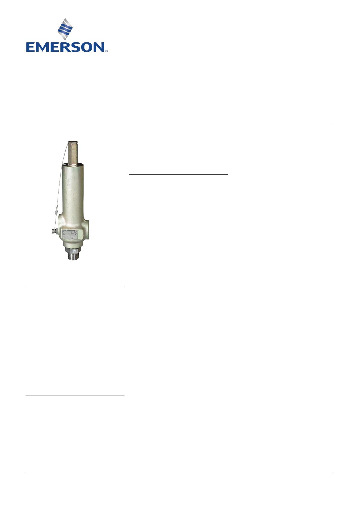
Installation and Maintenance Instructions for
Series 81 Spring Operated Pressure Relief
Valves (SOPRV).
The intent of these instructions is to acquaint
the user with the storage, installation and
operation of this product. Please read these
instructions carefully before installation.
1 GENERAL
The Anderson Greenwood Series 81 Relief Valve
is a direct acting spring loaded valve for gas
service and uses a plastic seat and O-ring seals.
The intent of these instructions is to acquaint
the user with the maintenance of this product.
Please read these instructions carefully. This
product should only be used in accordance
with the applicable operating instructions and
within the application specifications of the
original purchase order. The Installation and
2 VALVE REPAIR (-4, -6, -8 ORIFICE)
Refer to Figure 1
2.1 Disassembly
2.1.1 Relieve spring tension and back
blowdown adjusting screw out two turns.
2.1.2 Remove inlet bushing, bushing seal and
valve internals.
2.1.3 Separate nozzle from guide by hitting top
of spindle on soft surface.
2.2 Repair
2.2.1 Hold spindle by skirt O.D. in soft jaw vise
and replace seat.
2.2.2 Examine nozzle and polish out any
scratches or nicks. Replace if necessary.
2.2.3 To obtain better seat seal with PTFE at
low set pressures, burnish seat against
nozzle by chucking spindle in lathe and
holding nozzle against spindle. Burnish
with small force and for short time as
PTFE readily deforms.
VCIOM-06062-EN 19/03
2.3 Assembly
Assemble in reverse order of disassembly.
Donot lubricate spindle or guide. Make sure
the nozzle is fully and evenly seated in guide.
This is a press fit joint. Lubricate threads and
pressure adjustment screw tip.
2.4 Soft goods repair kit
The part numbers for soft goods repair kits are
listed below. Each kit contains the seat and all
seals for the pressure ranges indicated.
Engineering Doc. #05.9040.071 Rev. N
TABLE OF CONTENTS
1. General ........................................................... 1
2. Valve repair (-4, -6, -8 orifice) ....................... 1
3. Valve repair (F, G, H and J orifice) ................ 2
4. Valve adjustment ........................................... 3
5. Seat leakage .................................................. 4
6. Set pressure change ..................................... 4
Operational Safety Instructions (available at
Emerson.com/FinalControl) should be fully read
and understood before returning this product to
service after maintenance.
2
ANDERSON GREENWOOD SERIES 81 SPRING OPERATED PRESSURE RELIEF VALVES
INSTALLATION AND MAINTENANCE INSTRUCTIONS
FIGURE 2
Series 81 (F, G, H and J Orifices)
3 VALVE REPAIR (F, G, H AND J ORIFICE)
Refer to Figure 2
3.1 Disassembly
3.1.1 Relieve spring tension and back
blowdown screw out two turns.
3.1.2
Remove spring bonnet and valve internals.
Note: a pipe nipple can be attached to vent
holes in top of guide to facilitate removal.
(⅛”-NPT: F, G or ¼”-NPT: H, J)
3.1.3 Separate nozzle from guide by hitting top
of spindle on soft surface.
3.2 Repair
3.2.1 Hold spindle by skirt O.D. in soft jaw vise
and replace seat.
3.2.2 Examine nozzle and polish seating
surface as required. Replace if necessary.
3.3 Assembly
Assemble in reverse order of disassembly.
Do not lubricate spindle or guide. Make sure
the guide plugs, if used, are flush or below
the top guide surface. Refer to table for plug
requirements. Make sure nozzle is fully and
evenly seated in guide. This is a press fit joint.
Lubricate threads and pressure adjustment
screw tip.
Orifice Set pressure (psig) Quantity
F Above 354 2
G Above 223 2
H Above 227 3
J Above 142 3
Pressure adjustment
screw
Pressure seal
Spring washer
Spindle
Spindle
Drive pin
Blowdown
adjustment
screw
Guide
Guide
Seat
Bonnet seal
Bonnet
Seat
Blowdown seal
Nozzle seal
Nozzle
Nozzle
Body
Retainer screw
FIGURE 1
Series 81 (-4, -6, -8 Orifices)
• Parts contained in kit
Pressure
adjustment screw
Spring washer
Spindle
Spindle
Drive pin
Blowdown
adjustment
screw
Guide
Guide
• Seat
• Seat
• Blowdown seal
• Bushing seal
Nozzle
Nozzle
Body
Bushing
Retainer
screw
Orifice TFE/KEL-F
Set pressure range
Vespel
Set pressure range
psig kpag psig kpag
-4 04.4805.001 20-4000 138-27579 04.4805.002 4001 and up 27586 and up
-6 04.4805.003 20-1500 138-10342 04.4805.004 1501 and up 10349 and up
-8 04.4805.005 20-1500 138-10342 04.4805.006 1501 and up 10349 and up
3
ANDERSON GREENWOOD SERIES 81 SPRING OPERATED PRESSURE RELIEF VALVES
INSTALLATION AND MAINTENANCE INSTRUCTIONS
4 VALVE ADJUSTMENT
4.1 General
Two adjustments are provided on gas service
valves, one for adjusting the opening pressure
and one for adjusting the closing pressure.
4.2 Set pressure
Turn spring adjustment screw on bonnet in most
of the way. Increase pressure to desired level
and back out screw until valve pops. Lock screw
with jam nut and retest. Readjust as required.
4.3 Reseat pressure
To adjust blowdown, turn blowdown adjustment
screw IN to shorten blowdown; OUT to increase
blowdown.
Note: if volume of test set up is too small,
blowdown will be set too short even though
pressure gauge indicates it to be correct.
Referto Section 4.5.
4.4 Adjustments tolerances
Two adjustments are provided on gas service
valves, one for adjusting the opening pressure
and one for adjusting the closing pressure.
SET PRESSURE RANGE
psig kpag Valve operating characteristic Tolerance*
Above 70 Above 483 Set pressure ±3%
70 and below 483 and below Set pressure ±2 psi (±13.8 kpa)
100 and above 689 and above Cracking pressure 95%
50 to 99 345 to 683 Cracking pressure 90 %
Below 50 Below 345 Cracking pressure 85%
100 and above 689 and above Reseat pressure 93%
50 to 99 345 to 683 Reseat pressure 90%
Below 50 Below 345 Reseat pressure 80%
* Percent tolerance is of specified set pressure
3.4 Soft goods repair kit
The part numbers for soft goods repair kits are listed below. Each kit contains the seat and seals
for all pressure ranges indicated.
Orifice TFE/KEL-F
Set pressure range
Vespel
Set pressure range
psig kpag psig kpag
4.5 Adjusting equipment
Where practical, valves should be set using
an accumulator large enough to accurately
read and set blowdown. For a -4 orifice up
to 4000psig (27579 kpag), -6 orifice up to
1410psig (9722 kpag) and a -8 orifice up to
600psig (4137kpag), a four cubic foot (0.113m
3
)
accumulator is recommended. Thesupply pipe
to the valve should be the same size as the inlet
or larger and not more than 10” (254 mm) long.
For all other valves, or if an accumulator is
not available for the sizes listed above, the
blowdown may be set using the following
method.
Turn the blowdown adjusting bolt all the way in
until it just touches the guide, then turn it out
the number of turns listed in the table.
F 04.4805.007 20-750 138-5171 04.4805.008 ≥ 751 ≥ 5178
G 04.4805.009 20-750 138-5171 04.4805.010 ≥ 751 ≥ 5178
H 04.4805.011 20-750 138-5171 04.4805.012 ≥ 751 ≥ 5178
J 04.4805.013 20-750 138-5171 04.4805.014 ≥ 751 ≥ 5178
4
ANDERSON GREENWOOD SERIES 81 SPRING OPERATED PRESSURE RELIEF VALVES
INSTALLATION AND MAINTENANCE INSTRUCTIONS
5 SEAT LEAKAGE
5.1 General
If the valve leaks after repair check the following:
5.1.1 Full and even seating of nozzle and guide.
5.1.2 Foreign particles trapped between the
seat and nozzle. If any are found they
may have damaged the seat, making it
necessary to replace it.
5.1.3 Correct seat material for the valve
set pressure.If items 1 and 2 reveal
no evident seat leakage source, the
procedures described in Section 5.2 may
be used to eliminate seat leakage. Section
5.2 applies only to teflon seated -4, -6, or
-8 orifice Series 81’s with nameplate set
pressures that do not exceed 300 psig
(2068 kpag).
5.2 Seat sealing procedures
Heat the valve for 15 to 30 minutes in a
oven preheated to 250-300°F (121-149°C).
Aconcentrated heat source such as a heat
gun or open flame must not be used. After
the valve has air-cooled to room temperature,
retest per Section 4.0 to insure seat tightness.
If results have not improved, the valve should
be disassembled and the seat replaced.
6 SET PRESSURE CHANGE
If the set pressure is changed more than ±5%
from the nameplate set pressure, the spring,
spring washers, spring bonnet, guide plugs and
seat may also have to be changed. Consult the
factory or refer to the soft goods repair kit, the
table in Section 3.3 and spring chart 03.0079.
BLOWDOWN ADJUSTMENT
Set pressure range
Orifice Turns out of blowdown screw psig kpag
Neither Emerson, Emerson Automation Solutions, nor any of their affiliated entities assumes responsibility for the selection, use or maintenance of any product.
Responsibility for proper selection, use, and maintenance of any product remains solely with the purchaser and end user.
Anderson Greenwood is a mark owned by one of the companies in the Emerson Automation Solutions business unit of Emerson Electric Co. Emerson Automation
Solutions, Emerson and the Emerson logo are trademarks and service marks of Emerson Electric Co. All other marks are the property of their respective owners.
The contents of this publication are presented for informational purposes only, and while every effort has been made to ensure their accuracy, they are not to be
construed as warranties or guarantees, express or implied, regarding the products or services described herein or their use or applicability. All sales are governed by
our terms and conditions, which are available upon request. We reserve the right to modify or improve the designs or specifications of such products at any time without
notice.
Emerson.com/FinalControl
-4 1 20-4000 138-27579
> 4000 > 27579
-6 ¾ 20-1410 138-9722
> 1410 > 9722
-8 20-600 138-4137
> 600 > 4137
-F 1 20-700 138-4826
> 700 > 4826
-G 20-700 138-4826
> 700 > 4826
-H, -J ¾ 20-700 138-4826
> 700 > 4826
  • Page 1 1
  • Page 2 2
  • Page 3 3
  • Page 4 4

Anderson Greenwood Series 81 Spring Operated Pressure Relief Valves Owner's manual

Type
Owner's manual

Anderson Greenwood Series 81 Spring Operated Pressure Relief Valves are designed for gas service and feature a direct-acting spring-loaded valve with a plastic seat and O-ring seals. They offer precise pressure relief with adjustable set and blowdown pressures, ensuring reliable operation in various gas applications. The valves are suitable for set pressures ranging from 20 to 750 psig (138 to 5171 kpag) and come in different orifice sizes (-4, -6, -8, F, G, H, and J) to accommodate varying flow requirements.

Ask a question and I''ll find the answer in the document

Finding information in a document is now easier with AI