MANUZOID
Explore
Explore
Bookmarks
Motorola
SYMBOL MT2000 Series
Motorola SYMBOL MT2000 Series Operating instructions
Type
Operating instructions
Brand
Motorola
Size
14.03 MB
Category
Radios
Pages
60
Language
English
View document
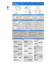
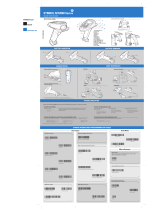
Motorola SYMBOL MT2000 Series Quick start guide
Type
Quick start guide
Brand
Motorola
Size
13.70 MB
Category
Bar code readers
Pages
2
Language
English
View document
Motorola SYMBOL MT2000 Series User guide
Type
User guide
Brand
Motorola
Size
4.60 MB
Category
Bar code readers
Pages
2
Language
English
View document
Motorola SYMBOL MT2000 Series User manual
Type
User manual
Brand
Motorola
Size
1.09 MB
Category
Bridge cameras
Pages
304
Language
English
View document
Motorola SYMBOL MT2000 Series User manual
Type
User manual
Brand
Motorola
Size
886.39 KB
Pages
17
Language
English
View document
Motorola SYMBOL MT2000 Series User manual
Type
User manual
Brand
Motorola
Size
563.48 KB
Pages
66
Language
English
View document
Motorola SYMBOL MT2000 Series User manual
Type
User manual
Brand
Motorola
Size
9.28 MB
Pages
170
Language
English
Table of contents
Contents
5
List of Tables
10
Related Publications Available Separately
11
Refer to Chapter 10 for ordering information.
11
Model Numbering System
12
Introduction
23
Test Equipment, Service Aids, and Tools
25
Recommended Test Equipment
25
Service Aids and Recommended Tools
26
Field Programming
26
Service Tools
28
Transceiver Performance Testing
29
General
29
Setup
29
Test Mode
29
RF Test Mode, HT 1000/JT 1000 Radios
29
a. (HT 1000 radios), a tone is emitted to indicate that the rf test mode has been entered.
30
b. (JT 1000 radios), the display will show the firmware version of the microprocessor for two sec...
30
Control Head Test Mode, HT 1000/JT 1000 Radios
31
RF Test Mode, MT 2000, MTS 2000, and MTX Series Radios
32
Control Head Test Mode, MT 2000, MTS 2000, and MTX Series Radios
32
Error-Code Displays
37
Power-up Display Codes
37
Operational Display Codes
38
Radio Alignment Procedure
39
General
39
Perform the following procedures in the sequence indicated.
41
Reference Oscillator Alignment
41
Front-End Pre-Selector (VHF/UHF only)
42
Rated Audio
42
Squelch
43
Transmitter Power
43
Transmit Deviation Balance (Compensation)
44
Transmit Deviation Limit
45
Transmit Deviation Limit Reference
45
VCO Crossover Frequency
46
Transceiver Board Identification
46
TX VCO Crossover Procedure
48
RX VCO Crossover Procedure
49
Signalling Deviation
49
DTMF Tuning
49
High Speed Signalling
49
MDC 1200
50
Alignment Procedure Conclusion
50
Disassembly and Reassembly
51
General
52
Disassembly to Board Level
52
a. Hold the radio such that the battery is tilted down.
52
b. Press down on the two battery-release levers.
52
c. With the release levers pulled down, the top of the battery will fall away from the radio.
52
d. Remove the battery completely from the radio.
52
a. Insert the chassis/front cover separation tool (Motorola part no. 6680334E07) or like instrume...
52
b. Pry the bottom of the chassis free from the cover by pushing the separation tool down and rota...
53
c. Lay the chassis down, and rotate the front cover back and partially away from the chassis (see...
53
a. Use the flex connector opening tool, large curved end (Motorola part no. 6680334E08), or like ...
54
b. Remove the flex from the chassis connector.
54
a. Loosen the front shield by prying each of the three clips (four tabs on early front shield) aw...
55
b. Insert a small, flat-blade screwdriver in the recessed area of the control top and pry the con...
55
c. Completely remove the control top/front shield/controls flex unit from the chassis.
55
Disassembly of Control Top
56
a. Five retaining clips hold the switch housing cover to the switch housing. Clips 1, 2, and 3 ar...
56
b. Using your thumbnail or small, flat-blade screwdriver, lift the tab that covers the base of th...
56
c. The cover will pop loose from the switch housing.
56
Disassembly of Front Cover Assembly
57
a. Disengage the retainer bracket leg that points toward the bottom of the front cover from its r...
57
(1) Insert a small, flat-blade screwdriver under the base of the bracket leg near the ring.
57
(2) Lift the bracket leg until it pops loose from under its retaining tab.
57
b. Lift the freed leg of the retainer bracket and use it to pull the remaining two legs of the br...
57
c. Pull the rubber microphone boot, containing the microphone, from its seated position. Unless y...
57
Reassembly
58
Keypad/Display Board (front display model radios only)
58
Front Cover Assembly
58
a. Position the spring bracket over the speaker, and toward the top of the front cover housing; i...
59
b. Grasp the center portion of the spring bracket (ring area) with thumb and forefinger.
59
c. While holding the ring area of the spring bracket at approximately the same height as the spea...
59
Chassis
60
Control Top
60
Control Top/ Front Shield/ Controls Flex as a Unit to Chassis
60
Front Cover Assembly to Chassis
61
Knobs, Antenna, and Battery
62
Maintenance
63
Introduction
63
Preventive Maintenance
63
Inspection
63
Cleaning
63
Safe Handling of CMOS Devices
64
Repair Procedures and Techniques
64
General
64
Specific
65
Exploded Views
73
Basic Radios and Basic Radios with Option Mate Optional Front Cover
74
Top-Display Radios
75
Keypad Radios
76
NUD7091B, NUD7092B, NUD/PMUD7095B, AND NUD7096B VHF (136-178MHz) TRANSCEIVER BOARDS’ PARTS LIST A...
84
Component Location Diagrams, Parts Lists, and Schematic Diagrams
79
Introduction
79
General
79
Transceiver
79
Controller
79
Schematic and Circuit Board Notes
79
Integrated Circuit Details with Pin-Out Names
80
Universal Connector Pin Numbers and Signal Assignments
83
Universal Connector Option Select (OPT SEL) Definition
83
NTN7512D/E, NTN7513E, NTN7857D/E AND NTN7858D/E CONTROLLER BOARDS’ PARTS LIST AND COMPONENT LOCAT...
124
Electrical Parts List, VHF Transceivers NUD7091B, NUD7092B, NUD/PMUD7095B, NUD7096B
85
NUE7265B, NUE7266B, NUE/PMUE7272B, AND NUE7274B UHF (403-470MHz) TRANSCEIVER BOARDS’ PARTS LIST A...
88
NUE7265B, NUE7266B, NUE/PMUE7272B, AND NUE7274B UHF (403-470MHz) TRANSCEIVER BOARDS’ SCHEMATIC DI...
91
Electrical Parts List, UHF Transceivers (403-470MHz) NUE7265B, NUE7266B, NUE/PMUE7272B, NUE7274B
89
NUD7091B, NUD7092B, NUD/PMUD7095B, AND NUD7096B VHF (136-178 MHz) TRANSCEIVER BOARDS’ SCHEMATIC D...
87
NUE7267B, NUE7268B, NUE/PMUE7273B, AND NUE7275B UHF (450-520MHz) TRANSCEIVER BOARDS’ PARTS LIST A...
92
Electrical Parts List, UHF Transceivers (450–520MHz) NUE7267B, NUE7268B, NUE/PMUE7273B, NUE7275B
93
NUE7267B, NUE7268B, NUE/PMUE7273B, AND NUE7275B UHF (450-520MHz) TRANSCEIVER BOARDS’ SCHEMATIC DI...
95
NUF6410B/C, NUF6498B/C, NUF6500B/C AND NUF6501C (800MHz) TRANSCEIVER BOARDS’ PARTS LIST AND COMPO...
96
Electrical Parts List, Transceivers (800MHz) NUF6410B/C, NUF6498B/C, NUF6500B/C AND NUF6501C
97
NUF6410B/C, NUF6498B/C, NUF6500B/C AND NUF6501C (800MHz) TRANSCEIVER BOARDS’ SCHEMATIC DIAGRAM (S...
99
NUF/PMUF6500D, NUF/PMUF6533A AND NUF/PMUF6410D (800MHz) TRANSCEIVER BOARD PARTS LIST AND COMPONEN...
100
Electrical Parts List, Transceiver (800MHz) NUF/PMUF6500D, NUF/PMUF6533A AND NUF/PMUF6410D
101
NUF/PMUF6500D, NUF/PMUF6533A AND NUF/PMUF6410D (800MHz) TRANSCEIVER BOARDS’ SCHEMATIC DIAGRAM (Sh...
103
NUF/PMUF6500D, NUF/PMUF6533A AND NUF/PMUF6410D (800MHz) TRANSCEIVER BOARDS’ SCHEMATIC DIAGRAM (Sh...
102
NUD7091B, NUD7092B, NUD/PMUD7095B, AND NUD7096B VHF (136-178MHz) TRANSCEIVER BOARDS’ SCHEMATIC DI...
86
NUF6499B/C AND NUF6502B/C (900MHz) TRANSCEIVER BOARDS’ PARTS LIST AND COMPONENT LOCATION DIAGRAMS
104
Electrical Parts List, Transceivers (900MHz) NUF6499B/C AND NUF6502B/C
105
NUF6499B/C AND NUF6502B/C (900MHz) TRANSCEIVER BOARDS’ SCHEMATIC DIAGRAM (Sheet 2 of 2)
107
NUF/PMUF6499D (900MHz) TRANSCEIVER BOARD PARTS LIST AND COMPONENT LOCATION DIAGRAMS
108
Electrical Parts List, Transceiver (900MHz) NUF/PMUF6499D
109
NUF/PMUF6499D (900MHz) TRANSCEIVER BOARDS’ SCHEMATIC DIAGRAM (Sheet 2 of 2)
111
NCN6145A/C, NCN6146A, NTN7089C, NCN6129C, NCN6138A, NCN6140A/B, NCN6141A, NCN/PMCN6140C CONTROLLE...
112
Electrical Parts List, Controller: NCN6129C And NCN6138A (all HT 1000 Models) NCN6140A/B (VHF HT ...
113
NCN6147A/B, NCN6150A/B, NTN7091D, NTN7620E, PMCN6147B AND PMCN6150B CONTROLLER BOARD POWER SECTIO...
123
NCN6129C, NCN6138A, NCN6140A/B, NCN/PMCN6140C, NCN6141A, NCN6145A/C, NCN6146A, NTN7089C AND PMCN6...
116
NCN6129C, NCN6138A, NCN6140A/B, NCN/PMCN6140C, NCN6141A, NCN6145A/C, NCN6146A, NTN7089C CONTROLLE...
115
NCN6129C, NCN6138A, NCN6140A/B, NCN/PMCN6140C, NCN6141A, NCN6145A/C, NCN6146A, NTN7089C CONTROLLE...
117
Electrical Parts List, Controllers NCN6147A/B, NCN6150A/B, NTN7091D, NTN7620E, PMCN6147B, PMCN6150B
119
Electrical Parts List, Controllers NTN7512D/E Front Display VHF, UHF and 800MHz Radios NTN7513E F...
125
NTN7512D/E, NTN7513E, NTN7857D/E AND NTN7858D/E CONTROLLER BOARD TOP-LEVEL SCHEMATIC
128
NTN7512D/E, NTN7513E, NTN7857D/E AND NTN7858D/E CONTROLLER BOARD POWER SECTION SCHEMATIC DIAGRAM
129
NCN6106C, NCN/PMCN6153A/B, AND NCN/PMCN6176A CONTROLLER BOARDS’ PARTS LIST AND COMPONENT LAYOUT D...
130
Electrical Parts List, Controllers NCN6106C, NCN/PMCN6153A/B, NCN/PMCN6176A
131
FRONT COVER DISPLAY FLEX AND CONTROLS FLEX SCHEMATIC DIAGRAMS
136
NCN6147A/B, NCN6150A/B, NTN7091D, NTN7620E, PMCN6147B AND PMCN6150B CONTROLLER BOARD DIGITAL SECT...
121
NCN6147A/B, NCN6150A/B, NTN7091D, NTN7620E, PMCN6147B AND PMCN6150B CONTROLLER BOARD TOP-LEVEL SC...
122
NCN6147A/B, NCN6150A/B, NTN7091D, NTN7620E, PMCN6147B AND PMCN6150B CONTROLLER BOARD ANALOG SECTI...
120
NCN6106C , NCN/PMCN6153A/B, NCN/PMCN6176A CONTROLLER BOARD ANALOG SECTION SCHEMATIC DIAGRAM
132
NCN6106C, NCN/PMCN6153A/B AND NCN/PMCN6176A CONTROLLER BOARD DIGITAL SECTION SCHEMATIC DIAGRAM
133
NCN6106C AND NCN/PMCN6153A/B AND NCN/PMCN6176A CONTROLLER BOARD TOP-LEVEL SCHEMATIC
134
NCN6106C, NCN/PMCN6153A/B AND NCN/PMCN6176A CONTROLLER BOARD POWER SECTION SCHEMATIC DIAGRAM
135
NUE7265B, NUE7266B, NUE/PMUE7272B, AND NUE7274B UHF (403-470MHz) TRANSCEIVER BOARDS’ SCHEMATIC DI...
90
NUE7267B, NUE7268B, NUE/PMUE7273B, AND NUE7275B UHF (450-520MHz) TRANSCEIVER BOARDS’ SCHEMATIC DI...
94
NUF6410B/C, NUF6498B/C, NUF6500B/C AND NUF6501C (800MHz) TRANSCEIVER BOARDS’ SCHEMATIC DIAGRAM (S...
98
NUF6499B/C AND NUF6502B/C (900MHz) TRANSCEIVER BOARDS’ SCHEMATIC DIAGRAM (Sheet 1 of 2)
106
NUF/PMUF6499D (900MHz) TRANSCEIVER BOARDS’ SCHEMATIC DIAGRAM (Sheet 1 of 2)
110
NCN6129C, NCN6138A, NCN6140A/B, NCN/PMCN6140C, NCN6141A, NCN6145A/C, NCN6146A, NTN7089C AND PMCN6...
114
NTN7512D/E, NTN7513E, NTN7857D/E AND NTN7858D/E CONTROLLER BOARD ANALOG SECTION SCHEMATIC DIAGRAM
126
NTN7512D/E, NTN7513E, NTN7857D/E AND NTN7858D/E CONTROLLER BOARD DIGITAL SECTION SCHEMATIC DIAGRAM
127
NCN6147A/B, NCN6150A/B, NTN7091D, NTN7620E, PMCN6147B AND PMCN6150B CONTROLLER BOARD’ PARTS LIST ...
118
Replacement Parts Ordering
137
Introduction
137
Motorola Online
137
Mail Orders
137
Telephone Orders
138
FAX Orders
138
Parts Identification
138
Product Customer Service
138
Appendix Figure 1. Secure Module
140
Appendix A
139
Secure Modules: NTN7279A, NTN7280A, NTN7281A, NTN7282A, and NTN7283A for MTS 2000 Radios
139
Introduction
139
Circuit Description
139
Appendix A Table 1. MTS 2000 Single Key Secure Module I/O Definition
140
Troubleshooting Secure Operations
141
Appendix A Table 2. Key Variable Loader
142
Service Aid
142
Retrofit Instructions
142
Secure Alignment Procedure
144
Appendix A Table 3. Secure Deviation
145
Removal And Installation
146
Appendix Figure 2. Secure Module Location Detail
147
Appendix A Table 4. RSS Secure Parameters
148
Appendix B
149
Model History Tables
149
Appendix B Table 1. HT 1000 Models
149
Appendix B Table 2. JT 1000 Models
151
Appendix B Table 3. MT 2000 Models
152
Appendix B Table 4. MTS 2000 Models
155
Appendix B Table 5. MTX Series Models
161
View document
Motorola SYMBOL MT2000 Series User manual
Type
User manual
Brand
Motorola
Size
7.86 MB
Category
Radios
Pages
170
Language
English
View document