Honeywell 800-08115 User manual
- Category
- Networking
- Type
- User manual

800-08115 1/11 Rev. B
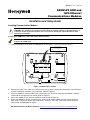
GSMVLP5 GSM and
ILP5 Ethernet
Communications Modules
Installation and Setup Guide
Installing Communication Modules
RF Exposure
WARNING: The antenna(s) used for this transmitter must be installed to provide a separation distance of
at least 20 cm from all persons and must not be co-located or operating in conjunction with any other
antenna(s) or transmitter.
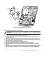
Installing the GSMVLP5 in the LYNX Touch Series Control
Ensure that SIM card and the connector board are securely installed in the GSMVLP5 before installing the
module in the LYNX Touch.
1. Install the provided FCC/IC label (P/N 800-08334) on the control’s case back (refer to Figure 1).
5000-100-186-V0
THIS DEVICE COMPLIES WITH PART 15 OF FCC RULES AND RSS 210 OF INDUSTRY
CANADA. OPERATION IS SUBJECT TO THE FOLLOWING TWO CONDITIONS: (1) THIS
DEVICE MAY NOT CAUSE HARMFUL INTERFERENCE, AND (2) THIS DEVICE MUST
ACCEPT ANY INTERFERENCE RECEIVED, INCLUDING INTERFERENCE THAT MAY
CAUSE UNDESIRED OPERATION.
800-08126 1/11 Rev A
LYNX TOUCH SERIES
COMPLIES WITH FCC RULES, PART 68 FCC REGISTRATION NO.: AC3AL05BL5000
RINGER EQUIVALENCE: 0.1B
CONTAINS TRANSMITTER MODULE
IC: 7830A-MC55I
FCC ID: QIPMC55I
800-08334 2/11 Rev A
FCC ID: CFS-8DLLYNXTOUCH1
IC: 573F-LYNXTOUCH1
LYNX TOUCH SERIES
IC MODEL: LYNXTOUCHG1
Figure 1. FCC/IC Label Location
2. Release the LYNX Touch front case from the back case by depressing the two locking tabs at the top of the
unit with the blade of a medium size screwdriver (Refer to Figure 2).
3. Install the GSMVLP5 into the LYNX Touch control front case. Ensure that the connector board is properly
seated into the receptacle on the control (Refer to Figure 2).
4. Secure the GSMVLP5 with the three provided screws (Refer to Figure 2).
5. Enable the GSMVLP5 device, configure alarm reporting and module supervision and register the device.
Refer to the “Program the Radio” and “Diagnostics” sections in the LYNX Touch Series Installation and
Setup Guide (P/N 800-06834 or higher).
For Documentation and Online Support: http://www.security.honeywell.com/hsc/resources/MyWebTech
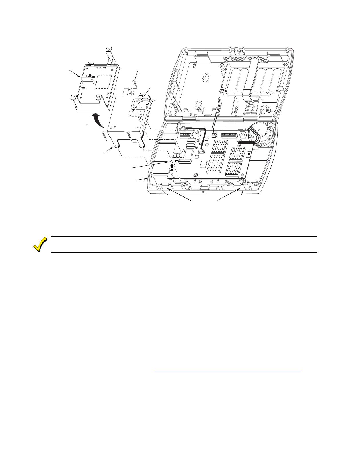
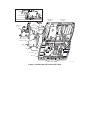
SCREW
(3)
SIM
CARD
5000-100-151-V1
ROTATED
180
CONNECTOR
BOARD
CONNECTOR
BOARD
RECEPTACLE
GSMVLP5
LYNX TOUCH
LOCKING TABS
Figure 2. Installing the GSMVLP5 in the LYNX Touch
Installing the ILP5 in the LYNX Touch Series Control
Ensure that the connector board and cable are securely installed in the ILP5 before installing the module
in
the LYNX Touch.
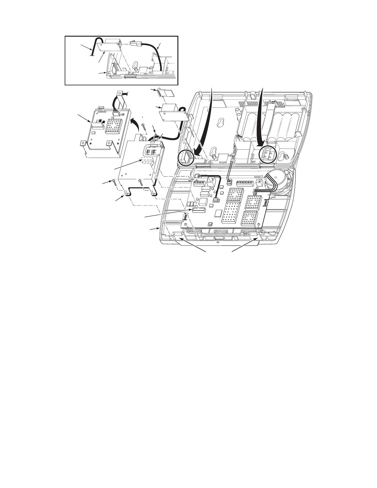
1. Release the LYNX Touch front case from the back case by depressing the two locking tabs at the top of the
unit with the blade of a medium size screwdriver (Refer to Figure 3).
2. Using a wire cutter or knife cut the plastic tabs that secure the ILP5 spacer to the back case of the LYNX
Touch (Refer to Figure 3).
3. Remove the ILP5 receptacle knockout from the left side of the LYNX Touch back case (Refer to Figure 3).
4. Install the ILP5 into the LYNX Touch control front case. Ensure that the connector board is properly seated
into the receptacle on the control (Refer to Figure 3).
5. Secure the ILP5 with the three provided screws (Refer to Figure 3).
6. Insert the ILP5 receptacle and spacer into the slot on the back case (Refer to Figure 3).
7. Secure the communications cable to the tie wrap point on the ILP5 with the provided tie wrap (Refer to
Figure 3).
8. Enable the ILP5 and configure alarm reporting and module supervision and register the device. Refer to the
“Program the Radio” and “Diagnostics” sections in the LYNX Touch Series Installation and Setup Guide
(P/N 800-06834 or higher).
For Documentation and Online Support: http://www.security.honeywell.com/hsc/resources/MyWebTech
5000-100-154-V1
SCREW
(3)
ROTATED
180
CONNECTOR
BOARD
RJ45
RECEPTACLE
CONNECTOR BOARD
RECEPTACLE
ILP5
LYNX TOUCH
TIE
WRAP
POINT
REMOVE ILP5
SPACER
ILP5 SPACER
REMOVE ILP5
KNOCKOUT
TIE
WRAP
(1)
RJ45 RECEPTACLE
LYNX TOUCH
ALTERNATE INSTALLATION
LOCKING TABS
ETHERNET CABLE
TO ILP5
Figure 3. Installing the ILP5 in the LYNX Touch

Electrical Specifications
GSMVLP5
Voltage Input 5V
Current
Idle 15 mA, standby
Average 300mA, average transmit
Peak 1.6A peak transmit, 25% duty cycle
ILP5
Voltage Input 5V
Current: 83 mA, 100 Base T with traffic
41 mA, 10 Base T with traffic
2 Corporate Center Drive, Suite 100
P.O. Box 9040, Melville, NY 11747
Copyright © 2011 Honeywell International Inc.
www.honeywell.com/security
Ê800-08115!Š
800-08115 1/11 Rev. B
-
 1
1
-
 2
2
-
 3
3
-
 4
4


Honeywell 800-08115 User manual
- Category
- Networking
- Type
- User manual
Ask a question and I''ll find the answer in the document
Finding information in a document is now easier with AI
Related papers
Other documents
-
 Lynx Studio Technology Aurora(N) User manual
-
Tascam MMP-16 User manual
-
Lynx LHEM48 Care & Use Manual
-
Victron energy Lynx Distributor Owner's manual
-
-
 Liquivision L1 User manual
-
-
ADT 5800RP-ADT Installation guide
-
Invacare PANTHER LX-4 User manual
-
Invacare LX-3PLUS User manual

