
LYNX EAVEMOUNT HEATER (LHEM48)
CARE & USE/INSTALLATION
MAKE THE MOST OF YOUR


CARE & USE/INSTALLATION
|
3
WARNINGS
WARNING
This product complies with ANSI standard Z83.26-2007/
Z83.26a-2008 and CSA 2.17-2007/CSA 2.37a-2008 and
has been tested an approved by Intertek.
To obtain replacement parts or se
rvice contact:
Lynx Grills, Inc.
62201 Hwy 82 West
Greenwood, MS 38930
888-289-5969
• Never use dented, rusty or damaged propane cylinders. Never store additional or empty propane
cylinders in the vicinity of this or any other appliance. Do not store propane cylinders indoors or on their
sides.
• Children should never be left alone or unattended in an area where this appliance is located. Install
your heater well away from areas where children play. Do not store items that may interest children in or
around the area of your heater.
• Never touch the heater face when hot. When in use, portions of the heater are hot enough to cause
severe burns.
• Always maintain the required clearances from combustibles as detailed. The heater is designed for
outdoor use only. Never use in a garage, building, shed, breezeway, or other enclosed area. Local codes
regarding head clearance requirements must be observed.
• Certain materials or items, when stored under the heater, will be subject to radiant heat and could be
seriously damaged.
• Gas heaters are not design certified for and are not to be installed in or on recreational vehicles, portable
trailers, boats or any other moving installation.
• Always have an ABC Fire Extinguisher accessible.
• Keep any electrical supply cord and the fuel supply hose away from any heated surfaces.
• Do not repair or replace any part of the heater unless specifically recommended in this manual. Other
service should be performed by a qualified technician.
• This appliance must be installed by a professional installer or technician. Be sure that he/she shows you
where your gas supply shut-off is located. All gas lines must have a shut-off valve that is readily and easily
accessible. If you smell gas, check for gas leaks immediately at the external pipe or hose connections.
Check only with a soap and water solution. Never check for gas leaks with an open flame. See section
“Checking for Gas Leaks” for further details.
• If you are using an LP gas tank, inspect the LP gas supply hose prior to each use of the accessory. If
there is evidence of excessive abrasion or wear, or the hose is cut, it must be replaced before using the
appliance.
• Never remove the grounding prong from the plug or use this product with an ungrounded, 2-prong
adapter.
THIS MANUAL MUST REMAIN WITH THE PRODUCT OWNER FOR FUTURE REFERENCE.

4
|
CARE & USE/INSTALLATION
WARNINGS
READ THIS MANUAL CAREFULLY and completely before using your heater to reduce the risk of:
1. Fire
2. Burn hazard, personal injury or property damage
3. Unapproved installation or servicing.
THIS PRODUCT IS DESIGNED FOR OUTDOOR USE ONLY. Improper installation, adjustment, alteration, service
or maintenance can cause property damage, injury or death.
Read this manual thoroughly before installation, use, or servicing of this product.
1. The burning of gas cooking fuel generates some by-products which are on the list of substances which are
known by the State of California to cause cancer or reproductive harm.
2. California law requires businesses to warn customers of potential exposure to such substances. To minimize
exposure to the substances, always operate this unit according to the use and care instructions found in this
manual. Be certain to provide adequate ventilation when cooking.
IF YOU SMELL GAS:
1. Shut off all gas supply lines to the heater.
2. Extinguish any open flames.
3. If odor continues, keep everyone away from the
heater and immediately call your gas supplier
or your fire department.
1. DO NOT store or use gasoline or other
flammable vapors and liquids in the vicinity of
this or any other appliance.
2. An LP cylinder not connected for use shall
not be stored in the vicinity of this or any
other appliance.
S’IL Y A UNE ODEUR DE GAZ:
1. Coupez l’admission de gaz de l’appariel.
2. Éteindre toute flamme nue.
3. Si l’odeur persiste, éloignez-vous de
l’appareil et appelez immédiatement le
fournisseur de gaz ou le service d’incendie.
1. Ne pas entreposer ni utiliser de l’essence ni
d’autres vapeurs ou liquides inflammables
dans le voisinage de l’appareil, ni de tout
autre appareil.
2. Une bouteille de propane qui n’est pas rac-
cordée en vue de son utilisation, ne doit pas
être entreposée dans le voisinage de cet
appareil ou de tout autre appareil.
WARNING
DANGER
WARNING
DANGER
AVERTISSMENT
WARNING! CALIFORNIA PROPOSITION 65

CARE & USE/INSTALLATION
|
5
WARNINGS
WARNING
STATE OF MASSACHUSETTS
• Massachusetts requires all gas be installed using a plumber or gas fitter carrying the appropriate
Massachusetts license.
• All permanently-installed natural gas or propane installations require a “T” handle type manual gas valve be
installed in the gas supply line to this appliance.
• This does not apply to portable propane installations using a 20 pound cylinder.
• The outdoor gas appliance and its individual shutoff valve must be disconnected from the gas supply piping
system during any pressure testing of that system at test pressures in excess of 0.5 psi (3.5 kPa).
• The outdoor gas appliance must be isolated from the gas supply piping system by closing its individual
manual shutoff valve during any pressure testing of the gas supply piping system at test pressures equal to
or less than 1/2 psi (3.5 kPa).
DANGER - CARBON MONOXIDE HAZARD
• This appliance can produce carbon monoxide which has no odor. If not installed, operated, and maintained
in accordance with manufacturers instructions, the emissions from this product can cause serious illness or
death. Never use this appliance in an enclosed space.
• Product installation must meet local electric codes or, in the absence of local codes, the latest edition of the
National Electrical Code ANSI/NFPA No. 70 or the Canadian Electrical Code CSA C22.1.
• Use only a Ground Fault Interrupter (GFI) protected circuit when plugging in the AC adaptor of this
appliance.
• This appliance is equipped with a low voltage, AC adaptor. All connecting cords must be for outdoor use.
Cords must have a “W-A” marking, and must be plugged directly into a properly grounded three prong
outlet.
• To protect against electric shock, do not immerse any part of the extension cord or any plugs in water or
other liquid.
• Unplug the AC adaptor from its power source when long periods of time are anticipated for the appliance
to be out of use.
• Do not operate any outdoor appliance with a damaged cord, plug, or after the appliance malfunctions or
has been damaged in any manner. Contact the manufacturer for repair.
WARNING - ELECTRICAL GROUNDING

6
|
CARE & USE/INSTALLATION
FEATURES
Thank you for your purchase of our LYNX Deluxe Eave Mount Patio Heater. This product has been manufactured with
the highest quality materials available, and combines the most advanced, state of the art, internal components with
cutting edge, heater design technology. This product is sure to provide you many years of enjoyment and comfort.
The design elements of this heater including its Lynx, signature polished highlights, and slim attractive appearance,
allow it to be mounted with pride in highly visible locations of your home. It will most likely architecturally blend and
enhance any portion of your home in which you chose to install it. Please read this entire manual before attempting to
install or operate your new heater.
FEATURES OF YOUR LYNX EAVE MOUNT PATIO HEATER:
• Manufactured completely from Stainless Steel with welded construction
• Spark ignition with heat sensing safety pilot
• Slim, custom profile
• Attractive and adjustable heavy duty mounting brackets (extension is made from 6 GA, 3/16” thick stainless). Can
be adjusted from 10” to 18”
• Mounting pivot adjustability from 0 -30 degrees from the horizontal. Allows for a precise direction of heat.
• Decorative safety grill provides wind resistance and protection from sudden gusts.
• Convenient DC operation. Requires no 110V electrical routing for basic installation.
• Operates with an attractive wireless wall mounted, On-Off-Hi-Low switch.
• Operates additionally with a highly sophisticated touch screen, remote control device.
• Remote control provides 6 levels of heat adjustment for NG gas type and 3 levels for LP gas type.
• Heat adjustment is viewable as either digital temperature readout, or as a numerical readout displaying the 6 heat
levels.
• Infrared technology provides a burner that generates up to 35,000 BTU’s of heat. Adjustable down to 27,000 BTU’s
(LP) and 24,000 BTU’s (NG)
• 110 V AC Adaptor included.

CARE & USE/INSTALLATION
|
7
Special considerations should be made when selecting a location for your heater before installation. The most
important of which should be a location that will serve to be the most functional and useful in providing heat. Suggested
locations would be under an eave, on a wall of an open or partially enclosed patio, or on a fascia. This heater has been
thoroughly tested and certified to function during and after mild rain storms, and during mild wind conditions. Be aware
that by avoiding locations that subject your heater to constant wind or rain exposure will greatly extend the life or
your new heater. Other considerations include its mounting position in relation to combustible materials. Combustible
materials include wood, wood fascia, wood siding, stucco mounted over wood studs, vinyl siding, and drywall. See
installation diagrams that reference mounting distances.
MOUNTING CONSIDERATIONS
• Select a location that provides the most functionality.
• Avoid locations that are prone to direct wind or rain exposure.
• This heater provides ample heat and large heat adjustability. It does not have to be located at eye level, as, its high
output will allow a distant location to still be affective.
• Do not mount this heater indoors or in a totally enclosed room. It needs air to breathe and vent.
• Avoid locations that are in close proximity to combustible materials (see illustration diagrams and mounting dis-
tances)
• Avoid locations that are so low that the installation could cause danger for those passing by.
• Standard and preferred installation places the gas exit (and vented valve access cover) of the heater on the RIGHT
side. This position places the gas exit and the AC adaptor cord at the REAR of the heater installation. This method is
preferred, not only from a visual standpoint, but allows for slightly less pipe routing, and creates more pivot adjust-
ability. There are times where right side hook up is not practical. The left side installation is still acceptable and the
heater will perform equally as well. Simply consider that there will be slightly more gas line routing to perform.
• Do not mount heater within a close proximity to fire sprinklers (4 ft. minimum recommended) to avoid accidental
activation of the sprinklers.
• It is recommended that the AC adaptor be used and the DC battery operation used as a secondary ignition source.
Consider the proximity of the nearest 110V AC GFI grounded power outlet to the location of the heater. The power
cord on the AC adaptor is 24 In. long and plugs directly into the right side wall of the heater. If there is no AC GFI
grounded outlet near the desired installation site then one should be added by a qualified electrician. An outdoor
extension cord can also be used, on a temporary basis, to bring AC power to the adaptor plug location.
MOUNTING CONSIDERATIONS
CODE REQUIREMENTS
When connecting to a fixed fuel piping system the Installation must be in accordance with local codes, or in the absence
of codes, with the latest edition of the National Fuel Gas Code, ANSI Z224 (in Canada CAN/CGA-B149.1 and -B149.2).
If AC power is being routed for AC/DC Transformer hook-up, then the National Electrical Code ANSI/NFPA 70 shall ap-
ply (in Canada the Canadian Electrical Code CSA C22.1 Part 1 and Part 2 shall apply)

8
|
CARE & USE/INSTALLATION
VISIBLE LOSS OR DAMAGE
Be certain any visible damage to the carton is noted on
freight bill or express receipt and signed by the person
making delivery.
FILE CLAIM FOR DAMAGES IMMEDIATELY, regardless of
extent of damage.
CONCEALED LOSS OR DAMAGE
If damage is unnoticed until the heater is unpacked, notify
the transportation company or carrier immediately and
file a “concealed damage” claim with them. This should
be done within (15) days of the date delivery is made to
you. Be sure to hold on to the container for inspection. We
cannot assume responsibility for damage or loss incurred in
transit. (See “Contacting Lynx” for further details. page 31)
SPRINKLERS: This appliance must be located at an appropriate distance away from fire sprinklers (4ft min.
recommended) to avoid accidental activation of sprinkler. Ethylene glycol or propylene glycol must never be used
in fire sprinkler systems where heaters are present, as these substances may become flammable when heated. A
fire sprinkler professional must be consulted when heaters are installed where fire sprinklers are present to insure
that heaters and fire sprinklers are properly integrated. Specific guidelines can be found in NFPA 13 regarding
design and specifications for fire sprinkler systems near heaters.
BEFORE YOU START
WARNING
IF SHIPMENT ARRIVES DAMAGED
IMPORTANT NOTES
WHERE’S THE WIND?
When selecting a suitable location, consider important
factors such as exposure to the wind. Caution should be
used when heaters are located in areas with prevailing
winds.
HOW LONG IS YOUR RUN?
Keep all gas supply lines as short as possible because
gas lines lose pressure over distance and with each elbow
and tee that is added. This drop in pressure affects heater
performance.
MAXIMUM RUNS FOR ALL
APPLIANCES ON SUPPLY LINE
Run Length
3/4” Pipe (in feet)
Max BTU for all
Appliances on line
10 360,000
20 245,000
30 198,000
40 169,000
50 150,000
60 135,000
70 123,000
80 115,000

CARE & USE/INSTALLATION
|
9
CLEARANCE TO CONSTRUCTION
STRAIGHT MOUNTING
If the heater is to be mounted facing straight down with no angle on its pivot point, then the heater
must be mounted NO CLOSER than 14” from any overhead combustible construction. The side
clearances must be NO CLOSER than 12” to a side wall, and the rear clearances must be NO CLOSER
than 12” to a rear wall. Use the LOWEST pair of holes in the mounting bracket extension arms. See
illustration below.
ANGLED MOUNTING
If the heater is to be mounted at an angle up to 30 degrees on its pivot, then the heater must be
mounted NO CLOSER than 18” from any overhead combustible construction. The side clearances
must be NO CLOSER than 12” to a side wall, and the rear clearances must be NO CLOSER than 12”
to a rear wall. Use the HIGHEST pair of holes in the mounting bracket extension arms. See illustration
below.

10
|
CARE & USE/INSTALLATION
The heater is factory set to use either propane (LP) or
natural gas (NAT). This heater is dedicated to one of these
two gas types and it is not easily field convertible. It is
critical that the gas you use matches that which the heater
was set up for. You can verify that by checking the rating
plate.
The Rating plate lists model/serial numbers and gas type.
The rating plate is located in the following places:
• Attached to the top of the heater housing
• Inside the valve compartment, behind the access cover
Ensure that the gas supplied meets with the minimum
pressure requirements. Do not operate the heater on any
gas other than that for which the heater has been set.
Fuel WC Min-Max Inlet WC Min Under
Full Load at Valve
Nat Gas 6-10 in 5 in
LP 11-13 in 10 in
Water Column Requirements
It is important that the inlet gas piping system be size
properly for the gas appliance that it serves. Please use the
above chart for verification of the Gas Inlet Pressure
required for this product.
NATURAL AND LP GAS
All gas connections must be made by a qualified
technician, specifically trained in the installation
of this type of gas appliance. Some states or
provinces require this trained personnel be licensed.
Installations must be performed in accordance with
local codes, or in the absence of local codes, the
regulations governed by that state or provincince.
To ensure satisfactory performance, the gas suppply
line must be sized to accommodate the total BTU
requirements of all the gas-fired equipment that will be
connected to that line.
Additionally, each ‘T’ or elbow that is added to the line
can also reduce pressure. This drop in pressure can affect
overall heater performance.
• Calculate the total BTU output of all equipment and refer
to “Gas Supply Line Runs” for allowable run distances for
¾ inch pipe. Failure to meet these minimum requirements
may reduce performance of the heater and any other
appliances running on that supply line.
• Always keep supply line runs as short as possible.
• A minimum pipe size of ½” is required for inlet
piping. The supplied exit coupling of this heater is
½”NPT (female). A ½” lever-handled, manual gas
shut-off valve should be installed within 6 feet of the
appliance to allow emergency gas shut-off and provide
isolation for servicing.
• A gas shut-off valve must be installed in an easily
accessible location by a qualified plumber.
• Keep threading compound off of the first two pipe
threads to avoid having any small pieces of compound
break loose and clog a burner valve or orifice.
• All gas pipe connections to the heater must be sealed
with gas pipe compound or Teflon sealing tape. Prior
to use, the gas supply line should be checked for leaks
by applying a mild solution of soap and water. Never
use an open flame to check for leaks. See section titled
‘Checking for Gas Leaks’ on page 17.
•
IMPORTANT NOTE: There is a pressure tap built into the
valve system used on the Lynx Eave Mount Patio Heater.
To access this tap, remove the 2 screws which hold the
louvered plate on the END CAP of the heater. Remove this
plate and look for the 2 smaller, slotted, brass screws. The
uppermost screw is the OUTLET pressure (as seen when the
heater is pointed downward). The lower screw is the INLET
pressure. To access either inlet for taking measurements,
turn the screw until it becomes loose. It will not fall out, as,
it is captivated in the valve. Be sure to re-tighten screw after
pressure measurements have been taken (see pg 29).
GAS CONNECTION INFORMATION
Keep last two
threads clean

CARE & USE/INSTALLATION
|
11
A typical gas supply line might consist of ½” piping
beginning at the gas supply source. This line will be routed,
within the shortest possible distance, up to the vicinity of
the heater location (30 Ft. MAX). This line, as previously
mentioned, willhave a ½” lever- handled gas shut-off
valve installed in-line, and within 6-feet of the termination
point. After final heater positioning and mounting angle is
created, the pipe line is then routed directly to the ½” NPT
(female) coupling at the end of the heater. As an alternate
to this installation, after the gas line has been routed to
the vicinity of the heater, and after final positioning and
pivot angle has been determined, a short gas flex line can
be installed from the end of the hard pipe to the ½” NPT
(female) coupling on the heater. This flex line should be
1/2” I.D. (5/8” O.D.), Stainless Steel, with ½”MIP fittings at
both ends. A ½” FIP coupling will then be used to connect
the flex line to the hard pipe. The use of this flex line allows
for additional angle (pivot) adjustment of the heater after
installation has been complete.
GAS LINE PURGING
You should purge the gas line of air before attempting to
light the heater.
• Slowly turn on the main gas supply.
• With the gas on, loosen one connection near the
heater until you either ‘hear’ gas or ‘smell gas’. Tighten
connection immediately. This should purge the remaining
air from the lines.
GAS CONNECTION INFORMATION ...continued
ELECTRICAL CONNECTION INFORMATION
Touch Screen Remote Control- 6.0 V (four 1.5 V AAA batteries) supplied
Radio Frequency (Remote Control and Receiver) – 303.8 MHz
Heater Battery Supply- 6.0 V (four 1.5V AA batteries) supplied
Receiver Module – powered by battery supply and/or AC Adaptor
Valve and Pilot- rated @ 3 V DC
AC/DC Adaptor (Transformer)-Input AC 100-240V-0.3A, 60/50Hz Output 7.5V ---1000mA 10W Max, cord length -24 in
NOTE: If the AC/DC Transformer (Lynx P/N 33937) is NOT being used, then there is no preliminary electrical
preparation required. If the transformer IS going to be used, then there must be electrical considerations. A GFI
protected, 110 V grounded electrical power outlet must be placed within 24 inches of the end, DC jack receptacle on
the heater.
ELECTRICAL SUPPLY SPECIFICATIONS AND CONNECTIONS

12
|
CARE & USE/INSTALLATION
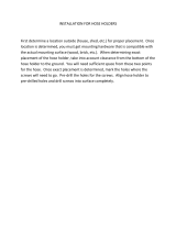
INSTALLATION
MOUNTING THE HEATER
Initial mounting considerations have been discussed, and now it’s time commit your placement theory into
motion. Consider the following pieces of information to help you through: The Lynx Eave Mount Patio Heater is
made from the finest materials available- heavy gauge stainless steel. As a result, this heater is heavy- It weighs
around 50 pounds and must be mounted securely. The ‘100 pound rule’ should be followed, whereas, it must be
mounted such that the anchors will support at least 100 pounds, or it may be considered a ‘suspension hazard’.
FAILURE TO INSTALL THE HEATER IN SUCH A MANNER MAY CAUSE THE HEATER TO FALL, RESULTING IN
PROPERTY DAMAGE, INJURY, OR DEATH. ADDITIONALLY, LOCAL CODES REGARDING HEAD CLEARANCE
REQUIREMENTS MUST BE OBSERVED.
Each mounting bracket is provided with (4) mounting holes. A quantity of (8) 5/16 x 1/1-2” Stainless lag bolts have
been provided for installation. If mounting into solid wood, for example, an eave joist , then only 2 holes (front to
back holes) per bracket need to be used (the inside holes nearest the vertical wall). Otherwise, use all (4) holes per
bracket. If mounting into a ‘hollow surface’, for example, stucco over wallboard and studs, , then 5/16” anchors, that
are appropriate for the mounting surface ,must be used (not provided).The distance between the outermost holes
of the mounting brackets, across the heater length , is 48”. This distance is intended to accommodate standard roof
joist spacing of 24” O.C. The distance between the innermost holes of the mounting brackets is 45-1/2”. The short
distance between the holes (side to side) on each mounting bracket is 1-1/4”. The long distance (front-to back) is
4-1/2” between the holes. See illustration.

CARE & USE/INSTALLATION
|
13
INSTALLATION...continued
Use only the mounting brackets provided with this
heater. Heater must be installed in a horizontal
manner parallel with the ground. The heater can,
however, be tilted upward to a maximum of 30
degrees. NEVER mount the heater on a vertical
axis. Such an installation is considered unsafe and
will void all warranties.
Important Note!
EAVE FASCIA MOUNTING
If the heater will be mounted on the fascia of an eave,
then the heater shall be mounted with the brackets in the
EXTENDED position only. The heater shall be mounted
in either the straight down position, or angled upward
to a maximum of 30 degrees AWAY from the house.
CAUTION: DO NOT MOUNT HEATER FACING TOWARD
the house. This position would allow exhaust heat to be
directed toward the combustible surfaces. It is important
to note that when mounting on a fascia the lower pivot
mounting screw (normally located within the curved slot)
will NOT be used.
In all mounting configurations, it is critical to NOT exceed a MAXIMUM pivot angle of 30 degrees. When using this
mounting configuration, since the lower pivot bolt will not be used, the maximum angle control slot will also not be
used.
The maximum 30 degree pivot angle can be determined by sighting the angled surface near the top of the heater.
When this surface is parallel with the ground, the heater is at 30 degrees ( See illustration on page 9). When mounting
on a fascia, NO PORTION OF THE HEATER SHALL BE CLOSER THAN 12 INCHES FROM THE FASCIA SURFACE.

14
|
CARE & USE/INSTALLATION
MOUNTING BRACKET ASSEMBLY
Locate and assemble the mounting brackets based on
your pre-determined mounting distance to the ceiling
(14” if mounting flat, 18” if mounting at an angle). Slide
the long bracket extension INSIDE the main mounting
bracket until the intended set of holes align. The entrance
slot is at the bottom of the main mounting bracket. For
each bracket, use quantity (2) ¼-20 x ½” Hex Bolts (pro-
vided).
Carefully insert each screw through the 2 larger holes of
the main mounting bracket and through the lower holes
(for the 14” position), OR through the 2 upper holes (for
the 18” position) of the mounting bracket extension.
Tighten both nuts securely. Snap the decorative cap over
each larger hole of the main mounting bracket. Repeat
for other bracket. See illustration.
After assembling the mounting brackets, they can be
installed in the pre-selected location. The spacing of the
outer-most sets of holes of the mounting brackets is 48”.
The spacing of the inner-most sets of holes is 45-1/2”. See
mounting bracket spacing diagram on page 12. These
numbers are given to you as a reference for planning.
Mount one single mounting bracket first. Choose the side
which may be the closest to a combustible material. This
way it is easier to measure and determine that the exact
minimum clearance is being adhered to. If mounting onto
wood predrill pilot holes using ¼” drill. (If surface is other
than wood, then anchors will be needed - follow instructions
that come with the anchors) If the mounting bracket is
resting entirely on the wood surface mount using all (4) screws
per bracket. It mounting on the edge of a wood joist then use
the 2 holes closest to the vertical wall of the bracket. Install the second bracket 48” from outer-most set of holes on the
first bracket. THIS WILL CREATE A RESULTING DIMENSION OF EXACTLY 49-3/32” BETWEEN THE EXTENSION ARMS
OF THE BRACKET. If not, then re-measure and mark again. Pre-drill and mount the second bracket.
INSTALLATION...continued
Place the heater into location on the ground directly under the mounting
brackets. Using 2 people, and 2 ladders carefully lift the heater into position.
Place the heater inside the extension arms of the brackets and secure the
heater at both ends, first with (2) ¼-20 x 1” hex head bolts. Mount screws in
the UPPER holes first. Tilt the heater into the pre-determined angular position
(0-30 degrees). Install the second set of ¼-20 x 1” hex head bolts through
the curved slots directly below the first holes. The maximum 30 degree angle
will be achieved when the screw is ‘bottomed out’ at one end of the curved
slot. This angle can also be sited by looking at the angled surface on the back
of the heater. When the angled surface is PARALLEL to the ground (or the
ceiling) the then heater is at 30 degrees. DO NOT MOUNT THE HEATER
MORE THAN 30 DEGREES, as damage can occur to the protective grill. Al-
ways use the 2 bolts per side and always use the bottom curved slot for angle
positioning (EXCEPTION- eave fascia mounting does not require bottom bolt
for mounting).

CARE & USE/INSTALLATION
|
15
Gas connections will vary depending on heater mounting
location selected and the gas type (NG or LP) being used.
See also previous section ‘Gas Supply and Connections’.
Prior to mounting the heater, the gas connections were
considered and an overall routing ‘plan’ was established.
A minimum pipe size of ½” is required for inlet piping. The
supplied exit coupling of this heater is ½”FIP (female). A
½” leaver- handled manual gas shut-off valve should be
installed within 6 feet of the appliance to allow emergency
gas shut-off and provide isolation for servicing.
With the exception of flared fittings, all gas pipe
connections to the heater must be sealed with gas pipe
compound or Teflon sealing tape. Prior to use, the gas
supply line should be checked for leaks by applying a mild
solution of soap and water. Never use an open flame to
check for leaks. See section titled ‘Checking for Gas Leaks’,
page 17.
Run the gas line to the vicinity of the heater. It is
recommended that the gas line be securely fixed to the wall
or mounting surface. WARNING: do not run gas line in a
location that it can be tripped over or in a location that
passes by either the heat output or the exhaust of the
heater. This gas line can now be attached directly to the
heater using a series of elbows and short sections of straight
pipe (nipples), sufficient to lead gas piping from the wall to
the inlet of the heater. The final fitting will be a ½”NPT male
pipe to mount directly into the heater. A 30” Stainless Steel
flexible line ½” I.D. (5/8” O.D.) with ½” MIP (male) fittings at
both ends. A ½” FIP (female) coupling would then be used
to connect the flex line to the hard pipe.
Please note that when gas is hard piped, an external
gas-pressure regulator is not required as the heater is
equipped with an internal, built-in gas-pressure regulator as
part of the gas control valve.
An alternative to the hard pipe installation (NG or LP) is to
use a metal flex hose which mounts directly from the main
gas source and extends directly into the heater inlet. See
illustrations below for installation techniques.
GAS CONNECTIONS
MAKING THE GAS CONNECTONS

16
|
CARE & USE/INSTALLATION
The following leak test procedure is to be performed on all
newly installed gas pipes, fittings, and connections:
1. Create a soapy solution of 1 part dish soap and 3 parts
water.
2. Turn ON the fuel supply.
3. Apply the soap solution by squirt bottle or paint brush
on all connections and fittings.
4. If bubbles appear to ‘grow’ on any of the connections,
you have a gas leak. IMMEDIATELY turn OFF the gas
supply.
1. At the identified point of leakage, assure that the joint
was sealed with gas pipe compound or Teflon sealing
tape. If either of these are missing, then the connection
must be unassembled and reassembled with proper
sealing compound.
2. If the connection has the proper sealing compound,
then tighten the fittings further. Re-apply the soap
solution and re-test for gas leaks.
3. If gas leak still exists, then it is recommended that the
entire section of pipe and fittings around the leak be
unassembled. Examine each fitting and assure that
all threads are ‘true’ and that no fittings or pipe have
deformation. If so, replace them with new fittings.
Once again, apply sealing compound around all joints
and re-assemble the pipes and fittings. If a flexible gas
line is being used to connect the heater to the hard
piping, and the leak is at that section, then be certain
the fitting attached to the heater is the proper ½” MIP
fitting, and the fitting at the other end is also a ½”
MIP fitting used with a ½” coupling to join to the ½”
pipe. Very often, a flex hose such as this is created with
removable fittings at the ends to create the ½” MIP
thread. These removable fittings themselves use a flare
thread, and not a pipe thread.
4. NEVER USE SEALING COMPOUND OR TEFLON TAPE
ON FLARED FITTINGS.
5. Reapply soap solution on all fittings and repeat as
necessary until all leaks have been sealed.
6. If a leak appears at an LP cylinder valve, DO NOT
ATTEMPT to repair it. Shut off the gas immediately.
The only way to safely resolve a damaged cylinder is to
replace it.
GAS CONNECTIONS...continued
CHECKING FOR GAS LEAKS
To prevent fire or explosion, DO NOT smoke or
allow any potential source of ignition (sparks,
electrical arcing, cell phones, etc.) in the area
while performing a leak test. Leak tests should
be conducted outdoors only. Never conduct a
leak test using fire or open flame.
DANGER!
FIXING A GAS LEAK

CARE & USE/INSTALLATION
|
17
ELECTRICAL CONNECTIONS
If the AC adaptor is NOT being used, and it is intended to
run the heater from battery power only, then NO
special electrical connections are needed. Note that this
may require more frequent battery replacements. The AC/
DC output plug, at the right end of the heater, is covered
with the rubber plug that is mounted under the jack.
If the AC adaptor IS being used, the battery
function becomes secondary and an approved, GFI
protected, grounded, 110V AC, OUTDOOR outlet box
and electrical receptacle must be installed within 24 in. of
the AC/DC output plug. This outlet must be installed by a
qualified electrician and must be sheltered from rain, snow,
and ice.
Plug the transformer directly into the GFI protected outlet.
Plug the jack, into the corresponding jack receptacle of
the heater. Secure any loose or dangling wires with tape,
wire ties, or insulated wire staples.
For an alternate to this connection, run an outdoor rated
extension cord from the closest GFI protected 110 V
grounded outlet to the heater. This cord and connection
must be sheltered from the rain and must not be in direct
line with either the heat output of the heater OR the
exhaust gasses exiting the top of the heater. It is
recommended that this cord be secured to the wall ( or
similar structure) with either tape, wire ties or insulated wire
staples. This installation is considered a TEMPORARY
installation.
Select a location for this switch, but do not mount it at
this time. Select a location that is out of reach of children,
and is just LOW enough to be reached by an adult. It is
recommended that the wall switch be mounted near the
heater (within 10 ft) so the heater can both be SEEN and
HEARD during operation of the wall switch. This wall
switch mounts on a flat surface with the mounting screws
provided. Double sided tape (not provided) will also work
for this step.
Wireless Wall Switch-This unit uses (2) pre-installed 3V
Lithium Batteries CR2032. If batteries were not previously
installed, remove the cover by inserting a small screw driver
into one of the slots on the side. Twist the screw driver
slightly to snap open the cover from the body. (do not
attampt to remove the small screws at the bottom). Insert
the provided lithium batteries (Posiitive (+) side up), making
sure the edge of the battery is inserted UNDER the small
battery retaining clip. If the wall switch will be mounted with
the provided screws, then mount into position (while the
cover is still off) at this time. After mounted, snap the cover
back onto the wall switch body. See pictures below.
MAKING THE ELECTRICAL CONNECTIONS
WIRELESS WALL SWITCH
BATTERY INSTALLATION

18
|
CARE & USE/INSTALLATION
Touch Screen Remote Transmitter-remove the cover on
the back of the remote control unit and install (4) AAA 1.5 V
batteries. Take special note of the (+) and (-) terminals.
Heater- remove the (2) screws holding the louvered end
plate at the far, right end of the heater. This is the SMALLER
of the 2 access plates. The battery pack will be mounted
directly inside, on the endplate. Using a small Philips head
screwdriver remove the screw and slide off the battery box
cover. Replace or insert (4) AA 1.5 V batteries with attention
of the (+) and (-) terminals. Reinstall the battery box cover
and secure it in place with the Philips head screw. Leave
the louvered end plate off and let it hang straight down for
the next programming operation. See pictures below.
ELECTRICAL CONNECTIONS...continued

CARE & USE/INSTALLATION
|
19
INITIALIZING THE REMOTE CONTROL SYSTEM
On the wireless wall switch press the “OFF” button.
Confirm that the red LED flashes. The LED will flash every
time that any of the 4 buttons are pushed. This confirms
that the unit is functioning, and that the button selection
has been confirmed.
Press the ‘ON’ button on the wall switch to confirm. You
will hear ‘clicking’ coming from the heater. Press the ‘OFF’
button immediately and proceed to the next section ‘BASIC
OPERATION OF YOUR HEATER’ page 20. The receiver
is located inside the valve compartment and is accessible
through the louvered plate on the right END CAP of the
heater. If this plate is still off from the battery installation,
then proceed to the next paragraph. Otherwise, remove
the 2 screws holding the end plate in position, and rotate
the plate, from the bottom, until the plate is free from the
heater. Allow the plate to hang below the heater (it is
connected to the battery wires).
Look inside the compartment and locate the black vinyl
cover cap on the side of the module enclosure. Peel the
cap off with your finger nail or screw driver. Look inside the
box and notice the small button on the side of the receiver.
This is the LEARN button. See the illustration below. With
the wall switch in one hand, and a paper clip or the tip
of a writing pen in the other hand, press and release the
‘LEARN’ button of the receiver. You will hear one beep.
Now press the ‘ON’ button on the wall switch. Once the
code is accepted, you will hear four beeps in rapid
succession. You should now hear the pilot sparking rapidly.
This indicates that your programming was successful. If the
pilot did not begin to spark, then repeat the above
process. After programming, press the ‘OFF’ button to turn
the system off.
NOTE: The wireless wall switch can now be mounted (if
not previously mounted), on a flat surface, at your desired
location. Use the screws provided with the switch or double
sided tape for mounting (not provided).
PROGRAMMING YOUR REMOTE

20
|
CARE & USE/INSTALLATION
O
nce the wireless wall switch has been successfully
programmed, repeat the process with the touch screen
remote control. Once again, press the LEARN button on
the receiver. Release the LEARN button. You will now hear
a single beep. NOTE: If programming more than one unit,
press and release the LEARN button on all units before
turning the remote ON. Now push the lower center MODE
SET button on the transmitter until the word ‘ON’ is
displayed in the upper left hand corner. Once the code is
accepted, you will hear four beeps in rapid succession.
You should also hear the pilot sparking rapidly. This
confirms that the signal has been received, and your
programming was successful. Press the mode button until
‘OFF’ is displayed at the top right side of the screen. Re-
confirm proper functioning by turning the transmitter back
to ‘ON’ and listening for rapid sparking of the pilot. Once
confirmed, press the mode set button until ‘OFF’ appears,
to shut the system off.
Replace the plastic cap over the LEARN BUTTON access
hole. Replace the louvered end plate over the open end
of the heater and tighten the two screws. Take care not to
pinch wires when re-attaching the end plate.
Refer to the section ‘TOUCH SCREEN REMOTE CONTROL
OPERATION’ Page 21, to learn more about the remote
operations that are possible with your Lynx Heater.
BASIC OPERATION OF YOUR HEATER
Your new Lynx Eave Mount Patio Heater has been
designed with cutting edge technology and easily
operates with either the manual ON-OFF-HI-LOW wall
switch or with the use of a touch screen remote control.
Please study the section of this manual entitled ‘Remote
Control Operation’ to allow a full understanding of the
heater’s capabilities.
MANUAL OPERATION
1
. TURN THE GAS ON. If this is a Natural Gas (NG)
installation, turn the manual shut-off valve lever ¼ turn so
that the lever is parallel and in-line with the gas line. If this
is a Liquid Propane (LP) installation, open the gas cylinder
valve by a minimum of one full turn, and if connected to a
quick disconnect hose, turn the in-line valve lever by ¼
turn so that the lever is parallel and in-line with the gas
line.
2. At the wall switch, push the ‘ON’ button, and listen for the
pilot to spark rapidly. After the pilot sparks, you will hear
the small pilot flame ignite. Shortly after that, you will hear
the main burner of the heater ignite. When using the wall
switch, the heater will light on ‘HIGH’ regardless of the
previous setting when it was turned off. Allow the heater
to warm up for a few seconds, and then press the ‘LO’
button to adjust the heat downward. Each press of the
button will lower or raise the heat level by one increment.
If you hold the ‘HI’ button continuously, the heat level will
advance more rapidly. Likewise, when you press the ‘LO’
button, the heat will become lower by one increment, and
by pressing the ‘LO’ button continuously, the heat level
will decrease more rapidly. Push the “OFF’ button when
finished using the heater.
PROGRAMMING YOUR REMOTE...continued
W
hen the heater is being lit for the first time after
installation, or after hooking up a gas line for the first
time, the gas lines will need to purge themselves
of the air to fill with gas. Depend-ing on the length of
gas lines, this may take a few minutes or more. The
spark ignition system is designed to spark for 1
minute, and then time out. This is part of the ignition
safety system.
IMPORTANT NOTE
If this occurs, simply turn the wall switch to OFF, and then turn back to ON. The spark will return to its normal function.
Repeat this operation until the pilot lights. Once the pilot lights, the heater will light within seconds.
Page is loading ...
Page is loading ...
Page is loading ...
Page is loading ...
Page is loading ...
Page is loading ...
Page is loading ...
Page is loading ...
Page is loading ...
Page is loading ...
Page is loading ...
Page is loading ...
Page is loading ...
Page is loading ...
Page is loading ...
Page is loading ...
-
 1
1
-
 2
2
-
 3
3
-
 4
4
-
 5
5
-
 6
6
-
 7
7
-
 8
8
-
 9
9
-
 10
10
-
 11
11
-
 12
12
-
 13
13
-
 14
14
-
 15
15
-
 16
16
-
 17
17
-
 18
18
-
 19
19
-
 20
20
-
 21
21
-
 22
22
-
 23
23
-
 24
24
-
 25
25
-
 26
26
-
 27
27
-
 28
28
-
 29
29
-
 30
30
-
 31
31
-
 32
32
-
 33
33
-
 34
34
-
 35
35
-
 36
36


Ask a question and I''ll find the answer in the document
Finding information in a document is now easier with AI
Related papers
-
Lynx Pro Models Owner's manual
-
-
-
Lynx L30AGNG User manual
-
-
-
-
Lynx L36R-2005 Owner's manual
-
-
Lynx LPZAF-LP Owner's manual
Other documents
-
 HeatTrak HR-Therm3550 Installation guide
-
 Esschert Design TG5K Installation guide
-
Astria Fireplaces Altair DLX Instruction Sheet
-
Cannon sampford IXL User manual
-
 click CK2IN1HEA User manual
-
 Sampford IXL CANNON SERIES User Instructions
-
 Heat Controller Infrared Electric Patio Heater IRPH15SS User manual
-
-
 Heat Controller Patio Heater IRPH15SS User manual
-
AURATON 1300 User manual


