Page is loading ...

OWNER’S MANUAL & OPERATING INSTRUCTIONS
12039 Smith Ave.
Santa Fe Springs CA 90670
USA / 1-877-338-0999
www.championpowerequipment.com
SAVE THESE INSTRUCTIONS
Important Safety Instructions
are included in this manual.
MADE IN CHINA
REV 66520-20160315
66520
MODEL NUMBER
2 IN. WATER TRANSFER PUMP WITH
HOSE KIT
Capable of solids up to 9/16 in. diameter (Semi-Trash)

Have questions or need assistance?
Do not return this product to the store!
WE ARE HERE TO HELP!
Visit our website:
www.championpowerequipment.com
for more info:
• Product Info & Updates
• Frequently Asked Questions
• Tech Bulletins
• Product Registration
– or –
Call our Customer Care Team Toll-Free at:
1-877-338-0999
AN IMPORTANT MESSAGE ABOUT TEMPERATURE:
Your Champion Power Equipment product is designed and rated for continuous operation at ambient temperatures up to
40°C (104°F). When your product is needed your product may be operated at temperatures ranging from -15°C (5°F) to
50°C (122°F) for short periods. If the product is exposed to temperatures outside this range during storage, it should be
brought back within this range before operation. In any event, the product must always be operated outdoors, in a
well-ventilated area and away from doors, windows and other vents.
*We are always working to improve our products. Therefore, the enclosed product may differ slightly from the image on the cover.
For residents of California:
WARNING: This product contains chemicals known to the State of California to cause cancer or birth defects
and other reproductive harm.
WARNING: The engine exhaust from this product contains chemicals known to the State of California
to cause cancer and birth defects and other reproductive harm.

66520
TABLE OF CONTENTS
Introduction ............................ 1
Introduction .......................... 1
Water Transfer Pump .................... 1
This Booklet .......................... 1
Manual Conventions ....................... 2
Safety Rules ............................ 3
Controls and Features ..................... 5
Water Transfer Pump .................... 5
Parts Included ........................ 6
Wheel Kit .......................... 6
Hose Kit .......................... 6
Other ............................ 6
Assembly .............................. 7
Remove the Water Transfer Pump
from the Shipping Carton ................. 7
Install the Wheel Kit .................... 7
Install the Vibration Mounts ............... 7
Install the Handle ...................... 7
Add Engine Oil ........................ 8
Add Fuel ............................ 9
Operation ............................. 10
Water Transfer Pump Location ............ 10
Connecting a Hose Kit .................. 10
Priming Pump ........................ 11
Starting the Engine .................... 11
Stopping the Engine ................... 12
Operation at High Altitude ............... 12
Maintenance and Storage .................. 13
Engine Maintenance ................... 13
Oil ............................. 13
Spark Plugs ....................... 13
Air Filter ......................... 14
Cleaning ......................... 14
Adjustments ....................... 14
Maintenance Schedule ................ 14
Storage ............................ 15
Engine Storage ..................... 15
Water Transfer Pump Storage ........... 15
Winter Storage ..................... 15
Specifications .......................... 16
Engine Specifications .................. 16
Water Transfer Pump Specifications ......... 16
Spark Plugs ......................... 16
Maintenance Valve Clearance ............. 16
Fuel .............................. 16
Oil ............................... 16
An Important Message About Temperature .... 16
Parts Diagram ........................ 17
Parts List ........................... 18
Engine Parts Diagram .................. 19
Engine Parts List ..................... 20
Troubleshooting ......................... 21
2 IN. WATER TRANSFER PUMP
WITH HOSE KIT
Capable of solids up to 9/16 in. diameter (Semi-Trash)

1
ENGLISH 66520
Introduction
Congratulations on your purchase of a Champion Power
Equipment water transfer pump. CPE designs and builds
water transfer pumps to strict specifications. With
proper use and maintenance, this water transfer pump
will bring years of satisfying service.
Water Transfer Pump
This unit is a gasoline engine driven, impeller based water
transfer pump. It is designed to pump clear water only.
Record the model and serial numbers as well as date and place of purchase for future reference. Have this
information available when ordering parts and when making technical or warranty inquiries.
This Booklet
Every effort has been made to ensure the accuracy and
completeness of the information in this manual. We reserve
the right to change, alter and/or improve the product and
this document at any time without prior notice.
Champion Power Equipment Support
Model Number
Serial Number
Date of Purchase
Purchase Location
1-877-338-0999
66520
For Oil Type see ‘Add Engine Oil‘ section. For Fuel Type see ‘Add Fuel‘ section.
INTRODUCTION

2
66520 ENGLISH
This manual uses the following symbols to help differentiate between different kinds of information. The safety symbol
is used with a key word to alert you to potential hazards in operating and owning power equipment.
Follow all safety messages to avoid or reduce the risk of serious injury or death.
MANUAL CONVENTIONS
CAUTION indicates a potentially hazardous
situation which, if not avoided, may result in minor
or moderate injury.
CAUTION
CAUTION used without the safety alert symbol
indicates a potentially hazardous situation which, if
not avoided, may result in property damage.
CAUTION
DANGER indicates an imminently hazardous
situation which, if not avoided, will result in death
or serious injury.
DANGER
WARNING indicates a potentially hazardous
situation which, if not avoided, could result in
death or serious injury.
WARNING
If you have questions regarding your water transfer
pump, we can help. Please call our help line at
1-877-338-0999
NOTE

3
ENGLISH 66520
SAFETY RULES
Engine exhaust contains carbon monoxide, a
colorless, odorless, poison gas. Breathing carbon
monoxide will cause nausea, dizziness, fainting or
death. If you start to feel dizzy or weak, get to fresh
air immediately.
Operate water transfer pump outdoors only in a
well ventilated area DO NOT operate the water
transfer pump inside any building, enclosure or
compartment.
DO NOT allow exhaust fumes to enter a confined
area through windows, doors, vents or other openings.
DANGER
Rotating parts can entangle hands, feet, hair,
clothing and/or accessories.
Traumatic amputation or severe laceration can result.
Keep hands and feet away from rotating parts. Tie
up long hair and remove jewelry. Operate equipment
with guards in place. DO NOT wear loose-fitting
clothing, dangling drawstrings or items that could
become caught.
DANGER
The water transfer pump develops powerful force.
DO NOT move the water transfer pump when it is
in use. DO NOT use hoses or connectors that are
worn, damaged or frayed. DO NOT allow children or
unqualified persons to operate or service the water
transfer pump. DO NOT open top plug or drain plug.
DANGER
Sparks can result in fire or electrical shock.
When servicing the water transfer pump:
Disconnect the spark plug wire and place it where
it cannot contact the plug. DO NOT check for spark
with the plug removed. Use only approved spark
plug testers.
WARNING
The engine exhaust from this product contains
chemicals known to the state of California to cause
cancer, birth defects, or other reproductive harm.
WARNING
Read this manual thoroughly before operating your
water transfer pump. Failure to follow instructions
could result in serious injury or death.
WARNING
DO NOT pump gasoline and fuel oil mixtures,
detergents, acids, chemicals, beverages, pesticides,
fertilizers or any other flammable liquid or corrosive.
Pumping volatile liquids may result in an explosion
or fire. These liquids will corrode the pump and void
your warranty.
DANGER
DO NOT immerse this unit in water.
WARNING

4
66520 ENGLISH
SAFETY RULES
Improper treatment or use of the water transfer pump
can damage it, shorten its life and void your warranty.
Use the water transfer pump only for intended uses.
Operate only on level surfaces. DO NOT expose water
transfer pump to excessive moisture, dust, or dirt.
DO NOT allow any material to block the cooling slots.
DO NOT use the water transfer pump if:
– Equipment sparks, smokes or emits flames
– Equipment vibrates excessively
CAUTION
Exceeding the water transfer pump’s specification
for maximum head can damage the water transfer
pump and/or hose kits connected to it.
DO NOT modify the water transfer pump in any
way. DO NOT attempt to exceed the rated flow.
Attempting to increase the rated flow may damage
the unit and/or shorten its life.
CAUTION
Rapid retraction of the starter cord will pull hand and
arm towards the engine faster than you can let go.
Unintentional startup can result in entanglement,
traumatic amputation or laceration.
Broken bones, fractures, bruises or sprains could
result.
When starting engine, pull the starter cord slowly
until resistance is felt and then pull rapidly to avoid
kickback.
WARNING
Water pumped through this unit shall not be used
as drinking water.
WARNING
DO NOT pump salt, sludge, sewer, sea, or any other
type of water containing solid material.
WARNING
Fuel and fuel vapors are highly flammable and
extremely explosive.
Fire or explosion can cause severe burns or death.
Unintentional startup can result in entanglement,
traumatic amputation or laceration.
DANGER
When adding or removing fuel:
Turn the engine off and let it cool for at least two
minutes before removing the fuel cap. Loosen the
cap slowly to relieve pressure in the tank.
Only fill or drain fuel outdoors in a well-ventilated area.
DO NOT pump gas directly into the engine at the
gas station. Use an approved container to transfer
the fuel to the engine.
DO NOT overfill the fuel tank.
Always keep fuel away from sparks, open flames,
pilot lights, heat and other sources of ignition.
DO NOT light or smoke cigarettes.
When starting the engine:
DO NOT attempt to start a damaged engine. Make
certain that the gas cap, air filter, spark plug,
fuel lines and exhaust system are properly in
place. Allow spilled fuel to evaporate fully before
attempting to start the engine.
Make certain that the water transfer pump is resting
firmly on level ground.
When operating the water transfer pump:
DO NOT move or tip the water transfer pump during
operation.
DO NOT tip the water transfer pump or allow fuel
or oil to spill from the engine. Block the wheels to
prevent unintended movement.
When transporting or servicing the water transfer
pump:
Make certain that the fuel shutoff valve is in the off
position and the fuel tank is empty.
Disconnect the spark plug wire.
When storing the water transfer pump:
Store away from sparks, open flames, pilot lights,
heat and other sources of ignition.

5
ENGLISH 66520
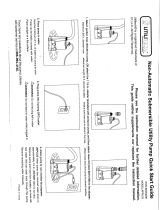
Water Transfer Pump
CONTROLS AND FEATURES
Read this owner’s manual before operating your water transfer pump. Familiarize yourself with the location and
function of the controls and features. Save this manual for future reference.
(1) Fuel Tank – 0.9 gal. (3.4 L) capacity fuel tank.
(2) Air Filter – Protects the engine by filtering dust
and debris from the air intake.
(3) Muffler
(4) 2 in. (5.1 cm) Outlet – 2 in. (5.1 cm) NPT outlet
connector.
(5) Low Oil Sensor – Senses the level of oil in the
crankcase and shuts the engine down if the level
falls too low.
(6) 8 in. (20.3 cm) Never Flat Wheels
(7) Drain Plug
(8) 2 in. (5.1 cm) Inlet – 2 in. (5.1 cm) NPT inlet
connector.
(9) Handle
(10) Throttle Lever – Used to adjust engine speed.
(11) Choke lever– Used to start the engine.
(12) Recoil Starter – Used to start the engine.
(13) Support Leg with Anti-Vibration Mounts
(14) Fuel Valve – Used to turn fuel supply on and off to
engine.
(15) Engine Switch – Used to start the engine.
(16) Oil Filler Cap – Check and fill engine oil level.
(17) Priming Plug – Used to prime the pump.
41
2
3
8
7
15
12
13
10
9
17
14
16
6
5
11

6
66520 ENGLISH
CONTROLS AND FEATURES
Parts Included
Your model 66520 gasoline powered Water transfer
pump ships with the following parts:
Wheel Kit
– 8 in. (20.3 cm) Wheel ....................2
– Bushing ..............................2
– Flange Bolt (M10x105 for Wheel) ............2
– Flat Washer ø10 ........................2
– Lock Nut (M10) ........................2
– Support Leg w/Vibration Mounts .............1
– Flange Bolt (M8x16 for Support Leg) ..........2
– Handle ..............................1
– Flange Bolt (M8x45 for Handle) .............2
– Nut (M8) .............................4
Hose Kit
– 12 ft. (3.7 m) Rigid Intake Hose .............1
– 20 ft. (6.1 m) Collapsible Outlet Hose .........1
– Teflon Tape ...........................1
– Clamp ............................... 3
– Outlet Hose Adapter .....................2
– Gasket ............................... 2
– Outlet Hose Fitting ......................2
– Strainer ..............................1
– Cam Lock Coupler .......................1
Other
– Spark Plug Socket ....................... 1
– Oil Funnel ............................1

7
ENGLISH 66520
Your water transfer pump requires some assembly.
This unit ships from our factory without oil. It must be
properly serviced with fuel and oil before operation.
If you have any questions regarding the assembly
of your water transfer pump, call our help line at
1-877-338-0999. Please have your serial number and
model number available.
Remove the Water Transfer Pump from the
Shipping Carton
1. Set the shipping carton on a solid, flat surface.
2. Remove everything from the carton except the
water transfer pump.
3. Carefully cut each corner of the box from top to bottom.
ASSEMBLY
Install the Wheel Kit
The wheel kit is not intended for over-the-road use.
CAUTION
Install the Handle
1. Place the handle over the mounting channel on the
frame.
2. Secure the handle to the frame using the two handle
bolts (M8x45).
3. Place a lock nut (M8) on the end of each bolt and
fasten securely. DO NOT over tighten the lock nuts.
You will need the following tools to install the wheels:
• 17 mm wrench OR adjustable wrench (not included)
• Socket wrench with a 16 mm socket (not included)
1. Slide the M10x105 wheel bolt through the washer,
sleeve and wheel.
2. Slide the bolt through the mount point on the frame.
3. Fasten securely with the M10 nut.
4. Repeat steps 1-3 to attach the second wheel.
Install the Vibration Mounts
1. Attach the support leg with rubber vibration mounts
to the frame cross member using a flange bolt
(M8x16) and nut (M8).
2. Thread the flange bolt through the vibration mount
and the frame.
3. Secure with nut. Tighten, but DO NOT over tighten.
4. Repeat steps 1-3 for second other side of the leg.

8
66520 ENGLISH
ASSEMBLY
Add Engine Oil
Add Engine Oil Cont’d.
1. Place the Water transfer pump on a flat, level
surface.
The engine is equipped with a low oil shut-off and
will stop when the oil level in the crankcase falls
below the threshold level.
CAUTION
DO NOT attempt to crank or start the engine before
it has been properly filled with the recommended
type and amount of oil. Damage to the Water
transfer pump as a result of failure to follow these
instructions will void your warranty.
CAUTION
Check oil often during the break-in period. Refer to the
Maintenance section for recommended service intervals.
NOTE
The recommended oil type is 10W-30 automotive oil.
NOTE
Synthetic oil may be used after the 5 hour initial
break-in period. Using synthetic oil does not
increase the recommended oil change interval.
NOTE
We consider the first 5 hours of run time to be
the break-in period for the unit. During the break
in period stay at or below 50% of the running
watt rating and vary the load occasionally to allow
stator windings to heat and cool. Adjusting the
load will also cause engine speed to vary and help
seat piston rings. After the 5 hour break-in period,
change the oil.
NOTE
Once oil has been added, a visual check should show
oil about 1-2 threads from running out of the fill hole.
If using the dipstick to check oil level, DO NOT screw
in the dipstick while checking.
NOTE
Weather will affect engine oil and engine
performance. Change the type of engine oil used
based on weather conditions to suit the engine
needs.
NOTE
2. Remove oil fill cap/dipstick to add oil.
3. Add up to 0.6 qt. (0.6 L) of oil (not included) and
replace oil fill cap/dipstick. DO NOT OVERFILL.
4. Check engine oil level daily and add as needed.
Full Synthetic 5W-30
Degrees Celsiusº
(Outside)
(Outside)
Degrees Fahrenheitº

9
ENGLISH 66520
ASSEMBLY
Our engines work well with 10% or less ethanol
blend fuels. When using blended fuels there are
some issues worth noting:
– Ethanol-gasoline blends can absorb more water
than gasoline alone.
– These blends can eventually separate, leaving
water or a watery goo in the tank, fuel valve and
carburetor.
– With gravity-fed fuel supplies, this compromised
fuel can be drawn into the carburetor and cause
damage to the engine and/or potential hazards.
– There are only a few suppliers of fuel stabilizer
that are formulated to work with ethanol blend
fuels.
– Any damages or hazards caused by using
improper fuel, improperly stored fuel, and/
or improperly formulated stabilizers, are not
covered by manufacture’s warranty.
It is advisable to always shut off the fuel supply,
run the engine to fuel starvation and drain the tank
when the equipment is not in use for more than 30
days.
NOTE
Add Fuel Cont’d.
Add Fuel
1. Use clean, fresh, regular unleaded fuel with a
minimum octane rating of 85 and an ethanol content
of less than 10% by volume.
2. DO NOT mix oil with fuel.
3. Clean the area around the fuel cap.
4. Remove the fuel cap.
5. Slowly add fuel to the tank. DO NOT OVERFILL. Fuel
can expand after filling. A minimum of 6.4 mm (¼ in.)
of space left in the tank is required for fuel expansion,
more than 6.4 mm (¼ in.) is recommended. Fuel can
be forced out of the tank as a result of expansion if it is
overfilled, and can affect the stable running condition of
the product. When filling the tank, it is recommended
to leave enough space for the fuel to expand.
6. Screw on the fuel cap and wipe away any spilled fuel.
Use regular unleaded gasoline with a minimum
octane rating of 85.
Do not mix oil and gasoline.
Fill tank to approximately 6.4 mm (¼ in.) below the
top of the tank to allow for fuel expansion.
DO NOT pump gas directly into the generator at the
gas station. Use an approved container to transfer
the fuel to the generator.
DO NOT fill fuel tank indoors.
DO NOT fill fuel tank when the engine is running or hot.
DO NOT overfill the fuel tank.
DO NOT light cigarettes or smoke when filling the
fuel tank.
CAUTION
Pouring fuel too fast through the fuel screen may
result in blow back of fuel at the operator while filling.
WARNING

10
66520 ENGLISH
Water Transfer Pump Location
Place the water transfer pump in a well ventilated area.
DO NOT place the water transfer pump near vents
or intakes where exhaust fumes could be drawn into
occupied or confined spaces. Carefully consider wind
and air currents when positioning water transfer pump.
This water transfer pump must have at least 5 ft. (1.5
m) of clearance from combustible material. Leave at
least 3 ft. (91.4 cm) of clearance on all sides of the
water transfer pump to allow for adequate cooling,
maintenance and servicing.
Place the pump on a level surface free from any
obstructions or potential hazards. The pump should
be placed close to the water level to ensure maximum
pump performance.
Connecting a Hose Kit
1. Attach and thread the connector to the threaded flange.
2. Slide the flexible, outlet hose over connector and
secure with the hose clamp.
4. Fasten the quick coupler to the suction hose with
the hose clamp.
5. Wrap the 2 in. (5.1 cm) NPT inlet clockwise with
the Teflon tape provided. Carefully thread the male
connector to the intake port.
3. Insert quick coupler in the rigid suction hose.
Pump output will be affected by the type, length, and
size of the suction and discharge hoses. The pumping
height, also known as the total head, is the distance
from the water level to the point of discharge. As
this distance increases, pump output decreases. The
discharge capacity is greater than the suction capacity.
Therefore, it is important that the suction head is less
than the discharge head.
The time required to draw water from the source to
the pump (self-priming time) can be decreased by
minimizing the suction head.
OPERATION
Both the intake and discharge ports are 2 in.
(5.1 cm) NPT. Please insure the connectors to the
suction and discharge hose are 2 in. (5.1 cm) NPT
threaded.
NOTE
Connecting a Hose Kit Cont’d.
TOTAL HEAD
DISCHARGE HEAD
SUCTION HEAD

11
ENGLISH 66520
6. Attach the quick coupler to the male coupler and
lock in place with the cam lock.
7. Attach the strainer to the intake hose and secure
with the hose clamp.
8. Remove the top cap from the pump chamber and
completely fill the chamber with clean water. Tighten
the cap. DO NOT over tighten.
Connecting a Hose Kit Cont’d. Priming the Pump Cont’d.
OPERATION
Located on the outlet flange is the priming plug.
Remove the priming plug and fill pump body to the very
top of outlet flange with water. Reinstall the priming
plug. As the engine starts up, this will start the draw of
liquid into the pump. Located within the pump assembly
is the one-way valve. As you prime the pump housing
this one-way flap valve shuts off the opening to the
suction hose. The priming process is only required when
the pump housing is not full of water.
Starting the Engine
1. Make certain the water pump is on a flat, level
surface.
2. Flip engine switch (A) to “ON” position.
3. Rotate the fuel valve (B) to the “ON” position.
4. Move the choke lever (C) to the “Choke” position.
5. Move throttle lever to middle position. (D)
6. Pull the starter cord slowly until resistance is felt and
then pull rapidly.
7. As engine warms up, move the choke lever (C) to
“ R u n ”.
8. Move the throttle lever (D) to the “Fast” position.
Priming the Pump
DO NOT run the pump dry.
Running the pump dry can destroy the pump seals
and will void the warranty. If the pump was running
while dry, stop the engine and allow it to cool
thoroughly before filling the chamber with water.
WARNING
A
B
D
C
Ensure the priming plug is secure before pump
operation, if not secure the priming plug could be
ejected and water or other liquids could be pumped
through the top of the outlet flange.
NOTE

12
66520 ENGLISH
OPERATION
Starting the Engine Cont’d.
If the engine starts but does not run make certain
that the water pump is on a flat, level surface. The
engine is equipped with a low oil sensor that will
prevent the engine from running when the oil level
falls below a critical threshold.
NOTE
Keep choke lever in “Choke” position for 2 pulls of
the recoil starter. After 2 pulls, move choke lever to
the “Run” position for up to the next 3 pulls of the
recoil starter. Too much choke leads to spark plug
fouling/engine flooding due to the lack of incoming
air. This will cause the engine not to start.
NOTE
Pump performance can be adjusted using the
throttle. To decrease pump output, slide the throttle
to the right. To increase it, slide the throttle to the
left.
NOTE
DO NOT remove either top, or drain (bottom) plugs
while the water pump is on and running
Loss of pressure and suction will occur. Injury may
also occur.
WARNING
Stopping the Engine
1. Turn the fuel valve to the “OFF” position.
2. Let the engine run until fuel starvation has stopped
the engine. This usually takes a few minutes.
3. Move the throttle lever to slow position.
4. Press the engine switch to the “OFF” position.
Important: Always ensure that the Fuel Valve and the
Engine Switch are in the “OFF” position when the engine
is not in use.
If the engine will not be used for a period of two (2)
weeks or longer, please see the Storage section for
proper engine and fuel storage.
NOTE
Operation using the alternative main jet at
elevations lower than the recommended minimum
altitude can damage the engine. For operation at
lower elevations, the standard main jet must be
used. Operating the engine with the wrong engine
configuration at a given altitude may increase
its emissions and decrease fuel efficiency and
performance.
WARNING
Operation at High Altitude
The density of air at high altitude is lower than at sea
level. Engine power is reduced as the air mass and air-
fuel ratio decrease. Engine power and generator output
will be reduced approximately 3½% for every 1000
feet of elevation above sea level. This is a natural trend
and cannot be changed by adjusting the engine. At high
altitudes increased exhaust emissions can also result
due to the increased enrichment of the air fuel ratio.
Other high altitude issues can include hard starting,
increased fuel consumption and spark plug fouling.
To alleviate high altitude issues other than the natural
power loss, Champion Power Equipment can provide a
high altitude carburetor main jet. The alternative main
jet and installation instructions can be obtained by
contacting Customer Support. Installation instructions
are also available in the Technical Bulletin area of the
Champion Power Equipment internet site.
The part number and recommended minimum altitude
for the application of the high altitude carburetor main
jet is listed in the table below.
In order to select the correct high altitude main jet
it is necessary to identify the carburetor model. For
this purpose, a code is stamped on the side of the
carburetor. Select the correct main jet part number
corresponding to the carburetor code found on your
particular carburetor.
Carburetor
Code
Main Jet Part Number Altitude
P19-1-H
Standard 26 .131017. 0 0. H
3500 Feet
(1067 Meters)
Altitude 26.131017.00.01.H
P19-1-Z
Standard 26 .131017. 0 0. Z
Altitude 26 .131017. 0 0.01. Z
P19-1-Y
Standard 26 .131017. 0 0.Y
Altitude 26.131017.00.01.Y

13
ENGLISH 66520
MAINTENANCE AND STORAGE
The owner/operator is responsible for all periodic
maintenance.
Complete all scheduled maintenance in a timely manner.
Correct any issue before operating the water pump.
Never operate a damaged or defective water pump.
For service or parts assistance, contact our help
line at 1-877-338-0999.
NOTE
Maintenance, replacement, or repair of emission
control devices and systems may be performed
by any non-road engine repair establishment or
individual.
NOTE
WARNING
Improper maintenance will void your warranty.
WARNING
Engine Maintenance
To prevent accidental starting, remove and ground spark
plug wire before performing any service.
Oil
Change oil when the engine is warm. Refer to the oil
specification to select the proper grade of oil for your
operating environment.
1. Remove the oil drain plug with a 12 mm socket and
extension (not included).
2. Allow the oil to drain completely.
3. Replace the drain plug.
4. Remove oil fill cap/dipstick to add oil.
5. Add up to 0.6 qt. (0.6 L) of oil and replace oil fill
cap/dipstick. DO NOT OVERFILL.
6. Dispose of used oil at an approved waste
management facility.
Spark Plugs
1. Remove the spark plug cable from the spark plug.
2. Use the spark plug tool that shipped with your water
pump to remove the plug.
3. Inspect the electrode on the plug. It must be clean and
not worn to produce the spark required for ignition.
4. Make certain the spark plug gap is 0.7 - 0.8 mm or
(0.028 - 0.031 in.).
5. Refer to spark plug section on specifications page.
6. Carefully thread the plug into the engine.
7. Use the spark plug tool to firmly install the plug.
8. Attach the spark plug wire to the plug.
Oil Cont’d.
0.7 - 0.8 mm
0.028 - 0.031 in.
Once oil has been added, a visual check should show
oil about 1-2 threads from running out of the fill hole.
If using the dipstick to check oil level, DO NOT screw
in the dipstick while checking.
NOTE

14
66520 ENGLISH
MAINTENANCE AND STORAGE
Air Filter
1. Unscrew wing nut to remove the air filter cover.
2. Remove the foam element.
3. Wash in liquid detergent and water. Squeeze
thoroughly dry in a clean cloth.
4. Saturate in clean engine oil.
5. Squeeze in a clean, absorbent cloth to remove all
excess oil.
6. Reassemble the element.
7. Reattach the air filter cover and tighten wing nut.
Adjustments
The air-fuel mixture is not adjustable. Tampering with
the governor can damage your water pump and your
electrical devices and will void your warranty. CPE
recommends that you contact our service line at
1-877-338-0999 for all other service and/or adjustment
needs.
Maintenance Schedule
Follow the service intervals indicated in the following
maintenance schedule.
Service your water pump more frequently when
operating in adverse conditions.
Contact our help line at 1-877-338-0999 to locate the
nearest Champion Power Equipment certified service dealer
for your water pump or engine maintenance needs.
*To be performed by knowledgeable, experienced owners or
Champion Power Equipment certified dealers.
Use a damp cloth to clean exterior surfaces of the
engine.
Use a soft bristle brush to remove dirt and oil.
Use an air compressor (25 PSI) to clear dirt and debris
from the engine.
Cleaning
DO NOT spray engine with water.
CAUTION
Water can contaminate the fuel system.
Every 8 hours or daily
Check oil level
Clean around air intake and muffler
First 5 Hours
Change oil
Every 50 hours or every season
Clean air filter
Change oil if operating under heavy load or in hot
environments
Every 100 hours or every season
Change oil
Clean/Adjust spark plug
Check/Adjust valve clearance*
Clean spark arrester
Clean fuel tank and filter*
Every 250 hours
Clean combustion chamber*
Every 3 years
Replace fuel line

15
ENGLISH 66520
MAINTENANCE AND STORAGE
Water transfer pump Storage
1. Allow the water pump to cool completely before
storage.
2. Turn off the fuel supply at the fuel valve.
3. Drain the pump chamber thoroughly.
4. Clean the water pump according to the instructions
in the Maintenance section.
5. Once the pump is dry, spray WD-40 or similar
product into the pump housing through all ports and
drainage hole.
6. Store in a clean, dry place out of direct sunlight.
Winter Storage
Protect your Water transfer pump parts from freezing.
1. Apply all storage instructions from previous sections.
2. Make sure water pump hose is free of all water
before storing for winter.
3. In order to prevent the pump from freezing you will
need to insert RV antifreeze.
4. You will need approximately 6 ounces (177.4 ml) of
RV Antifreeze, a funnel, and approximately 12 in.
(30.5 cm) of garden hose or equivalent. See diagram
below.
5. Pour the antifreeze into the funnel, then pull on the
engine recoil starter to create suction in the pump
housing. Pull the recoil several times until antifreeze
comes out of the pump outlet. DO NOT START THE
ENGINE WHEN DO THIS. Only pull the recoil cord
if the fuel valve and engine switch are in the OFF
position.
Water transfer pump exhaust contains odorless and
colorless carbon monoxide gas.
To avoid accidental or unintended ignition of your
Water transfer pump during periods of storage, the
following precautions should be followed:
– When storing the Water transfer pump for short
or extended periods of time make sure that the
Engine Switch and the Fuel Valve are set in the
OFF position.
DANGER
Storage
For longer term storage, please follow these guidelines.
Engine switch should be in the “OFF” position while pulling
the recoil cord, and performing storage maintenance steps.
NOTE
Engine Stored for Less than 30 Days
1. Allow the engine to cool completely before storage.
2. Clean engine according to the Maintenance section.
3. To extend the fuel storage life add a properly
formulated fuel stabilizer to the tank.
4. Ensure the fuel valve is in the “OFF” position.
Engine Stored for Over 30 Days
1. Add a properly formulated fuel stabilizer to the tank.
2. Run the engine for a few minutes so the treated fuel
cycles through the fuel system and carburetor.
3. Turn the fuel valve to the “Off” position.
4. Let the engine run until fuel starvation has stopped
the engine. This usually takes a few minutes.
5. The engine needs to cool completely before cleaning
and storage.
6. Clean the engine according to the maintenance
section.
7. Change the oil.
8. Remove the spark plug and pour about 1⁄2 ounce
(14.8 ml) of oil into the cylinder. Crank the engine
slowly to distribute the oil and lubricate the cylinder.
9. Reattach the spark plug.

16
66520 ENGLISH
SPECIFICATIONS
Oil
Use 10W-30 automotive oil.
Oil capacity is up to 0.6 qt. (0.6 L).
DO NOT OVERFILL.
Please reference the following chart for recommended
oil types for use in the water transfer pump.
Fuel
Fuel capacity is 0.9 gal. (3.4 L). Use regular unleaded
gasoline with a minimum octane rating of 85 and an
ethanol content of no more than 10% by volume.
Water Transfer Pump Specifications
– Model ........................... 66520
– Inlet Diameter ..............2 in. (5.1 cm) NPT
– Outlet Diameter ............2 in. (5.1 cm) NPT
– Fuel Capacity ................ 0.9 gal. (3.4 L)
– Total Head .................. 98 ft. (29.9 m)
– Suction Head ..................26 ft. (7.9 m)
– Max Delivery Volume .....158 gal/min (598 L/min)
– Max Solid Waste .......9/16 in. diameter (1.4 cm)
– Gross Weight .............. 84.9 lb. (38.5 kg)
– Net Weight ..................66.1 lb. (30 kg)
– Height ................... 19.2 in. (48.8 cm)
– Width ...................20.8 in. (52.8 cm)
– Length. . . . . . . . . . . . . . . . . . . . 25 in. (63.6 cm)
Engine Specifications
– Model ......................YF168F-2-000
– Displacement .......................196cc
– Type ........................4-Stroke OHV
– Start Type .........................Recoil
Maintenance Valve Clearance
– Intake: 0.13 – 0.17 mm (0.005 – 0.007 in.)
– Exhaust: 0.18 – 0.22 mm (0.007 – 0.009 in.)
Note: Tech bulletin regarding the valve adjustment
procedure is on www.championpowerequipment.com.
An Important Message About Temperature
Your Champion Power Equipment product is designed
and rated for continuous operation at ambient
temperatures up to 40°C (104°F). When your product is
needed your product may be operated at temperatures
ranging from -15°C (5°F) to 50°C (122°F) for short
periods. If the product is exposed to temperatures
outside this range during storage, it should be brought
back within this range before operation. In any event,
the product must always be operated outdoors, in a
well-ventilated area and away from doors, windows and
other vents.
Spark Plugs
OEM spark plug: NHSP F6RTC
Replacement spark plug: NGK BPR6ES or equivalent
Make certain the spark plug gap is 0.7 - 0.8 mm or
(0.028 - 0.031 in.).
Weather will affect engine oil and engine
performance. Change the type of engine oil used
based on weather conditions to suit the engine
needs.
NOTE
Full Synthetic 5W-30
Degrees Celsiusº
(Outside)
(Outside)
Degrees Fahrenheitº

17
ENGLISH 66520
Parts Diagram
SPECIFICATIONS
29
30
25
22
21
15
16
17
20
1
2
3
4
6
7
8
9
10
11
12
13
14
15
16
17
18
19
14
15
14
23
24
26
27
28
37
33
34
3536
38 39
40
41 42
43 44 45
46
31
32
33
5
/